EP2096972B1 - Buse de nettoyage et procédé de nettoyage par aspiration - Google Patents
Buse de nettoyage et procédé de nettoyage par aspiration Download PDFInfo
- Publication number
- EP2096972B1 EP2096972B1 EP07849496A EP07849496A EP2096972B1 EP 2096972 B1 EP2096972 B1 EP 2096972B1 EP 07849496 A EP07849496 A EP 07849496A EP 07849496 A EP07849496 A EP 07849496A EP 2096972 B1 EP2096972 B1 EP 2096972B1
- Authority
- EP
- European Patent Office
- Prior art keywords
- rim
- nozzle
- rim portion
- floor surface
- vacuum cleaner
- Prior art date
- Legal status (The legal status is an assumption and is not a legal conclusion. Google has not performed a legal analysis and makes no representation as to the accuracy of the status listed.)
- Active
Links
Images

Classifications
-
- A—HUMAN NECESSITIES
- A47—FURNITURE; DOMESTIC ARTICLES OR APPLIANCES; COFFEE MILLS; SPICE MILLS; SUCTION CLEANERS IN GENERAL
- A47L—DOMESTIC WASHING OR CLEANING; SUCTION CLEANERS IN GENERAL
- A47L9/00—Details or accessories of suction cleaners, e.g. mechanical means for controlling the suction or for effecting pulsating action; Storing devices specially adapted to suction cleaners or parts thereof; Carrying-vehicles specially adapted for suction cleaners
- A47L9/02—Nozzles
- A47L9/06—Nozzles with fixed, e.g. adjustably fixed brushes or the like
- A47L9/0633—Nozzles with fixed, e.g. adjustably fixed brushes or the like with retractable brushes, combs, lips or pads
- A47L9/064—Nozzles with fixed, e.g. adjustably fixed brushes or the like with retractable brushes, combs, lips or pads actuating means therefor
- A47L9/0653—Nozzles with fixed, e.g. adjustably fixed brushes or the like with retractable brushes, combs, lips or pads actuating means therefor with mechanical actuation, e.g. using a lever
-
- A—HUMAN NECESSITIES
- A47—FURNITURE; DOMESTIC ARTICLES OR APPLIANCES; COFFEE MILLS; SPICE MILLS; SUCTION CLEANERS IN GENERAL
- A47L—DOMESTIC WASHING OR CLEANING; SUCTION CLEANERS IN GENERAL
- A47L2201/00—Robotic cleaning machines, i.e. with automatic control of the travelling movement or the cleaning operation
- A47L2201/06—Control of the cleaning action for autonomous devices; Automatic detection of the surface condition before, during or after cleaning
Definitions
- the invention relates to a vacuum cleaner nozzle bounding an inlet for guiding aspirated air through the nozzle and to a method for vacuum cleaning.
- a vacuum cleaner nozzle is known that is equipped with a rim extending along an outer end contour of the inlet for contacting a floor surface area when in an operating position on the floor surface.
- a portion of the rim is movable between a lowered position for contacting a floor surface or extending close to the floor surface and a lifted position for leaving spacing between the rim portion and the floor surface.
- a rim operating structure is provided for lifting and lowering the rim portion between the lowered position and the lifted position in a movement stroke of the nozzle over the floor surface in a direction.
- the rim operating structure includes a tongue engaging the floor surface.
- the tongue is pivotably movable in a directions generally parallel to the direction of movement of the nozzle over the floor surface between two positions.
- the tongue is connected to two rim portions on opposite sides if the inlet end contour for keeping lifted one of the nozzles in a first of the two positions and for keeping lifted the other one of the nozzles in the other of the two positions.
- the rim portions are each time lifted at the start of a stroke in a new direction. This allows larger particles to enter the contour of the outer end of the inlet, while the trailing rim slides over the floor, so that the nozzle does not have to be lifted from the floor and positioned over larger particles to be able to aspirate such larger particles.
- a disadvantage of such known vacuum cleaner nozzles is that fine dust and other dirt adhering to the floor surface are removed from the floor surface less effectively.
- this object is achieved by providing a vacuum cleaner nozzle according to claim 1.
- the invention may also be embodied in a method for vacuum cleaning according to claim 14.
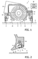
- a vacuum cleaner nozzle 1 according to the invention shown in Figs. 1-4 .
- Such a vacuum nozzle 1 can for example be part of a robotic vacuum cleaner of which a robotic vacuum cleaner head unit 16 is shown in Figs. 5 and 6 .
- the vacuum cleaner nozzle 1 bounds an inlet 2 for guiding aspirated air through the nozzle 1.
- the aspirated air can be transported towards for example a hose and/or to a dust bag in a canister unit of the vacuum cleaner via an air outlet 22.
- a rotating cleaning brush 5 is arranged such that outer ends of the brush hairs extend into inlet 2.
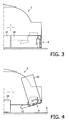
- a first rim portion 3 and a second rim portion 4 extend on opposite sides along the outer contour of the inlet 2. Both rim portions 3, 4 are movable between a lowered position for contacting the floor surface 6 or extending close to the floor surface 6, as is shown in Figs. 1 and 3 , and a lifted position for leaving a spacing between the rim portion 4 and the floor 6, as is shown in Figs. 2 , 4 and 6 .
- a rim operating structure is provided for lifting a rim portion 3, 4 from the lowered position to the lifted position.
- the rim operating structure is constituted by solenoids 21 that are connected to a nozzle control unit 23 for controlling displacements of the rim portions 3, 4 between the lifted and the lowered positions.
- solenoids instead of solenoids, many other types of actuators, such as electric motors or members operated by selective application of the vacuum in the inlet area thereto.
- the rim operating structure 21, 23 is also arranged for displacing both rim portions 3, 4 together between the lifted and the lowered position for adaptation of the vacuum nozzle 1 to the vacuum cleaning of carpets and the like.
- the operating structure 21, 23 may for example be adapted to act on data provided by a sensor indicating the type of floor surface being cleaned.
- both rim portions 3, 4 can be set in a lifted position ( Fig. 2 , 4 , 6 ). This allows the vacuum nozzle 1 to move towards the floor 6 relative to a drive unit 17 of the head unit, so that skid surfaces 12 contact the floor surface 6 when the rim portions 3, 4 are in the lifted position. Thus, when vacuuming a soft floor surface, the skid surfaces 12 will at least partially carry the vacuum nozzle.
- both rim portions 3, 4 are set in the lowered position, contacting the floor surface area 6 when the vacuum nozzle 1 is in an operating position on the floor surface 6.
- the rim operating structure 21, 23 is adapted for leaving the rim portion 3, 4 in the lowered position during a portion of a stroke and for subsequently, during a later portion of the stroke, starting the lifting of the rim portion to the lifted position.
- the portion or portions of the stroke during which the rim portions 3, 4 are left in the lowered position preferably include an initial portion of the stroke, so that during a stroke, a leading one of the rim portions 3, 4 is lifted only after there is a reasonable likelihood that one or more larger particles may have accumulated in front of that rim portion 3, 4.
- both the rim portions 3, 4 are in the lowered position shown in Fig. 1 .
- particles that are too big to pass under the lowered rim portions 3, 4 accumulate in front of the leading rim portion 4 of the vacuum nozzle 1 and are pushed forward by it.
- one of the rim actuator 21 lifts the leading rim portion 4 into the lifted position so that a spacing between the floor surface 6 and the rim portion 4 is created, causing larger particles that have accumulated in front of the leading rim portion 4 during this stroke to enter the contour of the outer end of the inlet 2, while the nozzle 1 continues to move over the floor.
- an entrance for larger particles is created by lifting the leading rim portion 4, while the trailing rim portion 3 remains in its lowered position.
- the nozzle 1 does not have to be lifted from the floor surface 6 and positioned over larger particles to be able to aspirate the larger particles and a reduced vacuum in the inlet 2 only occurs temporarily while nevertheless the larger particles are caused to enter the inlet area 2.
- the leading rim portion 4 is in its lifted position, the other rim portion 3, that remains in its lowered position, keeps the nozzle 1 lifted sufficiently far from the floor surface 6 to avoid that the skid surfaces 12 touch the floor.
- the rim portion 3 When the vacuum nozzle 1 is moved in a direction opposite to the one indicated by the arrow 7, the rim portion 3 will be the leading rim portion and will be the rim portion that is lifted while the, then trailing rim portion 4 remains in its lowered position.
- the rim operating structure 21 only temporarily lifts one of the rim portions 3, 4, just long enough for letting the larger particles that have accumulated in front of the leading one of the rim portions 3, 4 into the inlet 2, and is subsequently lowered again to regain the high vacuum level allowing fine dust and other dirt adhering to the floor surface 6 to be removed effectively.
- the moment when lifting of the leading rim portion 3, 4 is started is preferably determined in relation to an expected end of the stroke, for instance by determining when the nozzle is at a predetermined distance from the expected end of the stroke or by determining a point in time that is a predetermined period of time before the expected end of the stroke.
- the expected end of the stroke may for instance be determined from a sensed obstacle or change in the type of floor surface in a current direction of movement of the vacuum nozzle 1, or be determined from changes in the speed at which the vacuum nozzle 1 is travelling, a reduction of the speed indicating the imminent end of a stroke.
- the rim portion 3, 4 is be lifted before the stroke is ended and the cleaning nozzle changes its direction of movement, for example by cornering an obstacle or reversing its direction of movement.
- a strong vacuum is maintained while the larger particles are first accumulated in front of the leading rim portion 3, 4 and subsequently caused to enter the vacuum nozzle 1 by lifting the leading rim portion 3, 4 only once, at the end of the stroke. If the rim portion 3, 4 is lifted near or at the end of a stroke, a maximum amount of particles will have gathered in font of the leading rim portion 3, 4 when the vacuum level in the nozzle 1 is temporarily allowed to drop to allow the larger particles to enter the nozzle 1.
- the start of the lifting of the leading rim portion 3, 4 may also be determined in relation to a beginning of a stroke, for example by measuring a covered distance, and/or the elapse of a specified period of time from the start of a stroke.
- the rim portion 3, 4 may be simply lifted each time a certain distance has been covered, or a certain time interval has past.
- the duration of lifting the leading rim portion may for instance be, for each occasion, a predetermined period of time and/or covered distance of displacement of the nozzle 1 over the floor, or a percentage of the time or distance traveled before the rim portion 3, 4 was lifted.
- the leading rim portion 3, 4 can for example be lifted each time the vacuum nozzle 1 has traveled 2 meters and at end of each stroke.
- the control unit 23 may also be arranged to lift the leading one of the rim portions 3, 4 in response to a signal caused by a rim lift command from a user.
- control unit 23 is connected to a nozzle conducting system 25 of a robotic vacuum cleaner.
- a nozzle conducting system 25 contains data representing a track to be followed by the head unit 16. Because in such a system 25, the movements of the nozzle are generally predetermined (at least if no unforeseen obstacle is encountered), it is relatively simple to determine moments to lift the leading rim portion for allowing large particles to enter the nozzle 1 in such a manner, that the larger particles are caught effectively, yet the time and distance traveled over which the leading rim portion is lifted is kept very low. For instance, because the end of a stroke is known in advance, the leading one of the rim portions 3, 4 may then for instance be lifted automatically and very briefly yet long enough to catch the accumulated particles during a final portion of each stroke.
- the first rim portion 3 or the second rim portion 4 is each time lifted as a whole.
- the rim portions may be subdivided in for example separately liftable rim parts or the rim may be flexible and the rim operating structure may be arranged for individually lifting parts or portions of the rim or rims.
- the rim portion 3 is positioned along a first side of the contour of the outer end of the inlet 2 and the other rim portion 4 is positioned along a side of the contour of the outer end of the inlet 2 opposite the first side. In this way both rim portions 3, 4 alternately can function as the leading rim portion if the vacuum nozzle 1 is moved to and fro.
- the rim portions 3, 4 are U-shaped in bottom view and also extend along the sides of the vacuum nozzle 1. As is best seen in Fig. 3 , when in a lowered position, side flaps 14 of the rim portions 3, 4 extend along the sides of the vacuum nozzle 1. This is advantageous for obtaining an increased vacuum in the inlet 2 when vacuum cleaning hard floors. When the rim portion 3, 4 is in its lifted position, shown in Fig. 4 , the side flaps 14 point upwards along the side of the vacuum nozzle 1. This allows large particles that have accumulated against a wall or that have slipped to the side of the vacuum cleaner nozzle 1 to be drawn into the inlet 2 effectively.
- the rim portion 4 is hingedly suspended and is in this position pivoted inwardly from the lowered position of the rim portion 4, shown in Fig. 1 to its lifted position. Because the rim portion 4 pivots inwardly when moving from its lowered position towards its lifted position, it is avoided that particles accumulated in front of the rim portion 4 are moved away from the nozzle 1 when the rim portion 4 is lifted. Moreover, it is counteracted that particles stay clinging to the outside of the rim portion 4 since the rim portion moves away from the accumulated particles when being lifted and during and after lifting a strong air flow along the outer surface of the rim portion 4 is caused which is advantageous for entraining any particles clinging to the outside of the rim portion 4.
- the vacuum nozzle 1 In its lifted position, the rim portion 4 is oriented along the bottom surface of the suction inlet 2. Thus, the vacuum nozzle 1 can remain relatively compact compared to a nozzle storing the rim portion in a vertical position.
- the rim portion 4 has a guide surface 11 facing outwardly from the nozzle 1 when the rim portion 4 is in its lifted position.
- the guide surface 11 preferably extends at an angle of 5-30° and more preferably 10-20° relative to a plane defined by the contour of the inlet 2.
- the inner end of the guide surface 11 projects further in a direction perpendicular to that plane than the outer end of the guide surface, such that the inner end of the guide surface 11 is closer to the floor surface 6 than the outer end of the guide surface 11 when the nozzle I is in the operating position.
- the guide surface 11 of the rim portion 4 allows the nozzle 1 to slide over particularly large particles in a similar manner as a ski so that such particles also reliably reach the inlet 2.
- the guide surface 11 allows the nozzle to slide over larger particles and undulations in the surface.
- the rim portion 4 includes a strip-shaped brush 8 and a strip 9 that is continuous in its longitudinal direction and extends along the brush 8.
- the guide surface 11 includes a surface of the strip 9 facing away from the brush 8, when the rim portion 4 is in the lifted position.
- the strip 9 protects the brush and preferably is made of a flexible, low friction material for sliding over particles and floor surfaces.
- the brush 8 and the strip 9 are held in a holder 15, which holder also provides a portion of the guiding surface 11 for guiding the nozzle 1 over larger particles when the rim portion 4 is in its lifted position.
- a guide surface 13 of the skid plate 12 for contacting the floor surface when the whole rim portion 4 is in the lifted position is flush with the guide surface 11 of the rim portion 4 in its lifted position, thus complementing each other and allowing the nozzle to slide smoothly over larger particles so that such particles are reliably aspirated.
- Figs. 5 and 6 illustrate how the nozzle 1 shown in Figs. 1-4 may be integrated in a self propelled, self-steering vacuum cleaner head unit 16.
- a head unit is part of a robotic canister vacuum cleaner further including a self propelled, self-steering vacuum fan module and a hose assembly (both of which are not shown).
- An example of a robotic vacuum cleaner having a head unit connected to a vacuum fan module via a hose is disclosed in International Patent Application WO 02/074150 .
- the robotic vacuum cleaning head unit 16 has a drive system 17, comprising a drive and wheels 18 for propulsion and steering.
- the drive system 17 is located at a rear end of the robotic cleaning head unit 16, while the vacuum nozzle 1 is located at the front end.
- a hose connection tube 19 extends from the vacuum nozzle 1 to the rear of the robotic cleaning head unit 16 for connecting the air outlet 22 of the vacuum nozzle 1 with one end of a hose assembly (not shown).
- the robotic head unit 16 has sensors 20 for providing information about boundaries and obstacles in its surroundings.
- the sensors 20 can for example be used to determine the type of surface that is being cleaned, etc.
- the sensors are coupled to the nozzle conducting system 25 ( Fig. 1 ).
- Data regarding the surroundings can be provided to the nozzle conducting system 25 for processing and route planning.
- the control system of the robotic vacuum cleaner may, based on data provided by the sensors 20, map out a pattern of overlapping strokes, parallel to a border of the area, forming a track to be followed by the robotic head unit 16 and determining where the leading rim portion is to be lifted.
- the mapping and planning is done by the vacuum-fan module (also having sensors), which module subsequently sends the corresponding control signals to the cleaner head unit.
- a robotic vacuum head unit 16 is often wider than the vacuum nozzle 1, many robotic vacuum cleaners are not able to vacuum up to for example a wall. There will always be a small area along the wall, which cannot be vacuumed.
- the rim portions along the side of the vacuum nozzle may be independently moveable. For example, when following a track closely parallel to a wall, the rim portion facing the wall may be lifted to provide extra suction power for sucking in particles lying on the area out of direct reach of the vacuum nozzle.
- the vacuum nozzle 1 ends a stroke with the frontal rim portion 3, 4 facing the wall
- lifting the rim portion 3, 4 prior to reaching the end of the stroke prevents particles being pushed on the area out of reach of the vacuum nozzle 1.
- keeping the rim portion 3, 4 in a lifted position until the end of the stroke causes an intensive air flow from the wall to the inlet 2 along the floor 6 that causes a substantial portion of the particles lying close to the wall to be entrained into the inlet 2.
- the sensors 20 of the robotic vacuum cleaner head unit 16 can for example also be used for locating larger particles in advance, such that the rim portion 3, 4 can be lifted prior to reaching the particles, preventing that the particles are pushed forward by the vacuum nozzle 1, possibly hampering the steering and/or speed of the robotic head unit 16, prior to being picked up.
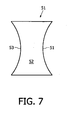
- the rim portions 53, 54 of the nozzle 51 bounding the inlet 52 may extends along a curved (rim portion 54) and/or V-shaped (rim portion 54) trajectory, a central section of the rim portion 53, 54 being located inwardly relative to outer sections of the rim portion 53, 54.
- larger particles are effectively kept in front of the leading rim portion 53, 54 while the nozzle 51 moves during the portion of the stroke prior to lifting of the rim portion 53 or 54, so that larger particles engaged by the rim portion 53, 54 remain in front of the nozzle 51 and are reliably aspirated when the rim portion 53, 54 is temporarily lifted.
- the rim portions 53 and 54 are of different shapes for illustrative purposes. Generally, it will be preferred that both the rim portions 53, 54 are of generally the same shape.
- a support such as a set of wheels, is provided that keeps the nozzle lifted to keep the space between the nozzle with the entire lifted rim and the floor wide enough to allow the larger particles to enter.
- This causes a relatively strong increase of the air displacement per unit of time through the inlet, which is advantageous for effectively entraining heavy particles through the inlet and may be effected using a more simple rim operating structure that is capable of lifting the entire rim only. It is also possible that only a single moveable rim is positioned along only a part of the contour.
- the rim portions in lifted position not only form a guide surface, but also function as skid surfaces, making separate skid surfaces unnecessary, for at least partially carrying the nozzle when vacuuming soft floor surfaces.
- a vacuum nozzle according to the invention can also be used without a cleaning brush 5, as part of a non-robotic vacuum cleaner or as part of a robotic vacuum cleaner in which the vacuum cleaner nozzle, the canister and the fan are integrated in a single self-propelled and self-steering unit.
Landscapes
- Engineering & Computer Science (AREA)
- Mechanical Engineering (AREA)
- Nozzles For Electric Vacuum Cleaners (AREA)
- Manipulator (AREA)
- Application Of Or Painting With Fluid Materials (AREA)
Claims (14)
- Buse d'aspirateur (1; 51) délimitant une entrée (2 ; 52) pour guider de l'air aspiré à travers la buse (1 ; 51), la buse (1 ; 51) comprenant :un bord (3, 4 ; 53, 54) le long d'un contour d'extrémité extérieure de l'entrée (2 ; 52) pour entrer en contact avec une zone de surface de sol (6) lorsqu'il se trouve dans une position de fonctionnement sur la surface de sol où au moins une partie de bord (3, 4 ; 53, 54) est mobile entre une position abaissée pour entrer en contact avec une surface de sol (6) ou pour s'étendre proche de la surface de sol (6) et une position relevée pour laisser un espacement ou au moins un plus grand espacement entre la partie de bord (3, 4 ; 53, 54) et la surface de sol (6) ; etune structure de fonctionnement de bord (21) pour relever et pour abaisser la partie de bord (3, 4 ; 53, 54) entre la position abaissée et la position relevée ;caractérisée en ce que la structure de fonctionnement de bord (21) est adaptée de manière à laisser la partie de bord (3, 4 ; 53, 54) dans la position abaissée pendant une partie d'une course de mouvement de la buse sur la surface de sol (6) dans une direction et par la suite pendant une partie ultérieure de la course, à partir du relevage à la position relevée.
- Buse d'aspirateur selon la revendication 1, dans laquelle la structure de fonctionnement de bord (21) est adaptée de manière à déterminer un moment pour le début du relevage de la partie de bord (3, 4 ; 53, 54) par rapport à une fin prévue de la course.
- Buse d'aspirateur selon la revendication 1 ou selon la revendication 2, dans laquelle la structure de fonctionnement de bord (21) est adaptée de manière à déterminer un moment pour le début du relevage de la partie de bord (3, 4 ; 53, 54) par rapport à un début de la course.
- Buse d'aspirateur selon l'une quelconque des revendications précédentes 1 à 3, dans laquelle la structure de fonctionnement de bord (21) est adaptée de manière à maintenir, chaque fois, la partie de bord (3, 4 ; 53, 54) dans la position relevée pendant une période prédéterminée de temps ou sur une distance prédéterminée de déplacement de la buse (1 ; 51) sur le sol (5).
- Buse d'aspirateur selon l'une quelconque des revendications précédentes 1 à 4, dans laquelle le bord (3, 4 ; 53, 54) est suspendu par articulation et dans laquelle le bord (3, 4 ; 53, 54), lorsqu'il se trouve dans la position relevée, se situe dans une position qui est pivotée vers l'intérieur à partir de la position abaissée du bord (3, 4 ; 53, 54).
- Buse d'aspirateur selon l'une quelconque des revendications précédentes 1 à 5, dans laquelle, dans sa position relevée, le bord (3, 4 ; 53, 54) présente une surface de guidage (11) faisant face à l'extérieur à partir de l'entrée (2 ;52) et s'étendant sous un angle dans la gamme comprise entre 5 et 30° par rapport à un plan qui est défini par le contour de l'entrée (2 ; 52), une extrémité intérieure de la surface de guidage (11) faisant plus loin saillie dans une direction qui est perpendiculaire audit plan qu'une extrémité extérieure de la surface de guidage (11) de telle façon que, lorsque la buse (1 ; 51) se situe dans la position de fonctionnement, l'extrémité intérieure de la surface de guidage (11) se situe plus proche de la surface de sol (6) que l'extrémité extérieure de la surface de guidage (11).
- Buse d'aspirateur selon la revendication 6, comprenant une plaque de protection (12) pour entrer en contact avec la surface de sol (6) lorsque le bord entier (3, 4 ; 53, 54) se situe dans la position relevée, la plaque de protection (12) ayant une surface de guidage (13) qui est alignée par rapport à la surface de guidage (11) du bord (3, 4 ; 53, 54) dans la position relevée.
- Buse d'aspirateur selon la revendication 6 ou selon la revendication 7, dans laquelle le bord (3, 4 ; 53, 54) comprend une brosse en forme de bande (8) et une bande (9) qui est continue dans sa direction longitudinale et qui s'étend le long de la brosse (8), et dans laquelle, lorsque le bord (3, 4 ; 53, 54) se situe dans la position relevée, la surface de guidage (11) comprend au moins une surface de la bande (9) qui se situe dans un sens s'éloignant de la brosse (8).
- Buse d'aspirateur selon l'une quelconque des revendications précédentes 1 à 8, dans laquelle la partie de bord (3, 4 ; 53, 54) est positionnée le long d'un premier côté du contour de l'extrémité extérieure de l'entrée (2 ; 52) et dans laquelle une nouvelle autre partie de bord (3, 4 ; 53, 54) est positionnée le long d'un côté du contour de l'extrémité extérieure de l'entrée (2 ; 52) à l'opposite du premier côté.
- Buse d'aspirateur selon la revendication 9, dans laquelle la partie de bord (3, 4 ; 53, 54) est mobile indépendamment de l'autre partie de bord (3, 4 ; 53, 54).
- Buse d'aspirateur selon l'une quelconque des revendications précédentes 1 à 10, dans laquelle, vu en élévation de dessous, la partie de bord (53, 54) s'étend le long d'une trajectoire courbée et/ou en forme de V, une section centrale de la partie de bord (53, 54) étant située à l'intérieur par rapport à des sections extérieures de la partie de bord (53, 54).
- Buse d'aspirateur selon l'une quelconque des revendications précédentes 1 à 11, dans laquelle au moins une des parties de bord (3, 4) s'étend le long d'un côté de la buse d'aspirateur (1).
- Aspirateur robotisé comprenant une unité automotrice et autodirectrice (16) comprenant une buse (1 ; 51) selon l'une quelconque des revendications précédentes 1 à 12, une unité conductrice de système (23) contenant des données qui représentent des directions déterminant une piste à suivre par l'unité (16), et dans lequel la structure de fonctionnement de bord (21) est adaptée de manière à déterminer quand relever le bord (3, 4 ; 53, 54) à partir des données qui représentent des directions déterminant une piste à suivre par l'unité (16).
- Procédé pour nettoyer une surface de sol (6) à l'aide d'une buse d'aspirateur (1 ; 51) délimitant une entrée (2 ; 52) pour guider de l'air aspiré à travers la buse (1 ; 51), la buse (1 ; 51) comprenant un bord (3, 4 ; 53, 54) le long d'un contour d'extrémité extérieure de l'entrée (2 ; 52) pour entrer en contact avec une zone de surface de sol (5) lorsqu'il se trouve en état de fonctionnement, où au moins une partie de bord (3, 4 ; 53, 54) est mobile entre une position abaissée pour entrer en contact avec une surface de sol (6) ou pour s'étendre proche d'une surface de sol (6) et une position relevée pour laisser un espacement ou au moins un plus grand espacement entre la partie de bord (3, 4 ; 53, 54) et la surface de sol (6) ; où la partie de bord (3, 4 ; 53, 54) est laissée entre la position abaissée pendant une partie d'une course de mouvement de la buse sur la surface de sol (6) dans une direction et par la suite, pendant une partie ultérieure de la course, la partie de bord (3, 4 ; 53, 54) est relevée à la position relevée.
Priority Applications (2)
| Application Number | Priority Date | Filing Date | Title |
|---|---|---|---|
| PL07849496T PL2096972T3 (pl) | 2006-12-21 | 2007-12-14 | Ssawka czyszcząca i sposób odkurzania |
| EP07849496A EP2096972B1 (fr) | 2006-12-21 | 2007-12-14 | Buse de nettoyage et procédé de nettoyage par aspiration |
Applications Claiming Priority (3)
| Application Number | Priority Date | Filing Date | Title |
|---|---|---|---|
| EP06126766 | 2006-12-21 | ||
| EP07849496A EP2096972B1 (fr) | 2006-12-21 | 2007-12-14 | Buse de nettoyage et procédé de nettoyage par aspiration |
| PCT/IB2007/055118 WO2008078238A1 (fr) | 2006-12-21 | 2007-12-14 | Buse de nettoyage et procédé de nettoyage par aspiration |
Publications (2)
| Publication Number | Publication Date |
|---|---|
| EP2096972A1 EP2096972A1 (fr) | 2009-09-09 |
| EP2096972B1 true EP2096972B1 (fr) | 2012-02-15 |
Family
ID=39322375
Family Applications (1)
| Application Number | Title | Priority Date | Filing Date |
|---|---|---|---|
| EP07849496A Active EP2096972B1 (fr) | 2006-12-21 | 2007-12-14 | Buse de nettoyage et procédé de nettoyage par aspiration |
Country Status (9)
| Country | Link |
|---|---|
| US (1) | US8732903B2 (fr) |
| EP (1) | EP2096972B1 (fr) |
| JP (1) | JP5075207B2 (fr) |
| CN (1) | CN101563014B (fr) |
| AT (1) | ATE545356T1 (fr) |
| BR (1) | BRPI0720836A8 (fr) |
| PL (1) | PL2096972T3 (fr) |
| RU (1) | RU2436491C2 (fr) |
| WO (1) | WO2008078238A1 (fr) |
Cited By (1)
| Publication number | Priority date | Publication date | Assignee | Title |
|---|---|---|---|---|
| WO2024010712A1 (fr) * | 2022-07-07 | 2024-01-11 | Irobot Corporation | Robot de nettoyage mobile à caractéristiques de nettoyage variables |
Families Citing this family (43)
| Publication number | Priority date | Publication date | Assignee | Title |
|---|---|---|---|---|
| AU2008200975B2 (en) | 2007-03-05 | 2012-09-27 | Bissell Inc. | Accessory tool for a vacuum cleaner |
| US9186028B2 (en) | 2007-03-05 | 2015-11-17 | Bissell Homecare, Inc. | Accessory tool for a vacuum cleaner |
| US9807925B2 (en) * | 2010-07-28 | 2017-11-07 | Deere & Company | Robotic mower area coverage system |
| EP2747625B1 (fr) * | 2011-08-23 | 2017-06-07 | Koninklijke Philips N.V. | Dispositif de nettoyage pour nettoyer une surface, comportant une brosse et un élément raclette |
| ES2610755T3 (es) | 2012-08-27 | 2017-05-03 | Aktiebolaget Electrolux | Sistema de posicionamiento de un robot |
| US9414728B2 (en) * | 2012-12-20 | 2016-08-16 | Koninklijke Philips N.V. | Cleaning device for cleaning a surface |
| AU2014100004A4 (en) | 2013-01-11 | 2014-01-30 | Bissell Inc. | Vacuum cleaner |
| EP2986192B1 (fr) | 2013-04-15 | 2021-03-31 | Aktiebolaget Electrolux | Dispositif de nettoyage sous vide robotisé |
| CN105101855A (zh) | 2013-04-15 | 2015-11-25 | 伊莱克斯公司 | 具有伸出的侧刷的机器人真空吸尘器 |
| CN104138238B (zh) * | 2013-05-08 | 2017-07-04 | 科沃斯机器人股份有限公司 | 清扫机器人和地面处理装置 |
| JP6204080B2 (ja) * | 2013-06-17 | 2017-09-27 | 東芝ライフスタイル株式会社 | 電気掃除機 |
| JP6638987B2 (ja) | 2013-12-19 | 2020-02-05 | アクチエボラゲット エレクトロルックス | 回転側面ブラシの適応速度制御 |
| EP3082537B1 (fr) | 2013-12-19 | 2020-11-18 | Aktiebolaget Electrolux | Dispositif de nettoyage robotisé et procédé de reconnaissance de point de repère |
| CN105792721B (zh) | 2013-12-19 | 2020-07-21 | 伊莱克斯公司 | 以螺旋样式移动的带侧刷的机器人真空吸尘器 |
| KR102099495B1 (ko) | 2013-12-19 | 2020-04-09 | 에이비 엘렉트로룩스 | 로봇 청소 장치가 장애물에 올라가는 것의 감지 |
| CN105849660B (zh) | 2013-12-19 | 2020-05-08 | 伊莱克斯公司 | 机器人清扫装置 |
| EP3084539B1 (fr) | 2013-12-19 | 2019-02-20 | Aktiebolaget Electrolux | Priorisation de zones de nettoyage |
| WO2015090402A1 (fr) | 2013-12-19 | 2015-06-25 | Aktiebolaget Electrolux | Dispositif de nettoyage robotisé à fonction d'enregistrement de périmètre |
| KR102116595B1 (ko) | 2013-12-20 | 2020-06-05 | 에이비 엘렉트로룩스 | 먼지통 |
| WO2016005012A1 (fr) | 2014-07-10 | 2016-01-14 | Aktiebolaget Electrolux | Procédé de détection d'une erreur de mesure dans un dispositif de nettoyage robotisé |
| JP6443897B2 (ja) | 2014-09-08 | 2018-12-26 | アクチエボラゲット エレクトロルックス | ロボット真空掃除機 |
| EP3190938A1 (fr) | 2014-09-08 | 2017-07-19 | Aktiebolaget Electrolux | Aspirateur robotisé |
| KR101622716B1 (ko) * | 2014-09-24 | 2016-05-19 | 엘지전자 주식회사 | 로봇 청소기 |
| EP3230814B1 (fr) | 2014-12-10 | 2021-02-17 | Aktiebolaget Electrolux | Utilisation d'un capteur laser pour la détection d'un type de sol |
| CN107072454A (zh) | 2014-12-12 | 2017-08-18 | 伊莱克斯公司 | 侧刷和机器人吸尘器 |
| KR102339531B1 (ko) | 2014-12-16 | 2021-12-16 | 에이비 엘렉트로룩스 | 로봇 청소 장치를 위한 경험-기반의 로드맵 |
| JP6532530B2 (ja) | 2014-12-16 | 2019-06-19 | アクチエボラゲット エレクトロルックス | ロボット掃除機の掃除方法 |
| US11099554B2 (en) | 2015-04-17 | 2021-08-24 | Aktiebolaget Electrolux | Robotic cleaning device and a method of controlling the robotic cleaning device |
| DE102015109838A1 (de) * | 2015-06-19 | 2016-12-22 | Vorwerk & Co. Interholding Gmbh | Saugdüse für einen Staubsauger |
| WO2017036532A1 (fr) | 2015-09-03 | 2017-03-09 | Aktiebolaget Electrolux | Système de dispositifs de nettoyage robotisés |
| CN108603935A (zh) | 2016-03-15 | 2018-09-28 | 伊莱克斯公司 | 机器人清洁设备以及机器人清洁设备进行陡壁检测的方法 |
| CN109068908B (zh) | 2016-05-11 | 2021-05-11 | 伊莱克斯公司 | 机器人清洁设备 |
| US20190133400A1 (en) * | 2016-05-11 | 2019-05-09 | Aktiebolaget Electrolux | Adjusting height of a robotic cleaning device |
| DE102016115977A1 (de) | 2016-08-26 | 2018-03-01 | Vorwerk & Co. Interholding Gmbh | Bodenplatte für eine Saugdüse bzw. ein Vorsatzgerät |
| DE102016118903A1 (de) * | 2016-10-05 | 2018-04-05 | Vorwerk & Co. Interholding Gmbh | Bürstenkopf für einen Staubsauger oder einen Saugroboter |
| WO2018074848A1 (fr) * | 2016-10-19 | 2018-04-26 | Samsung Electronics Co., Ltd. | Aspirateur robot |
| KR102683646B1 (ko) * | 2016-10-19 | 2024-07-11 | 삼성전자주식회사 | 로봇청소기 |
| DE102017208960A1 (de) | 2017-05-29 | 2018-11-29 | BSH Hausgeräte GmbH | Staubsauger mit einem motorisch betriebenen Dichtmittel |
| JP7243967B2 (ja) | 2017-06-02 | 2023-03-22 | アクチエボラゲット エレクトロルックス | ロボット清掃デバイスの前方の表面のレベル差を検出する方法 |
| DE102017117858A1 (de) * | 2017-08-07 | 2019-02-07 | Vorwerk & Co. Interholding Gmbh | Saugdüse zum Reinigen eines Bodens und Verfahren zur Anpassung einer Saugdüse an einen zu reinigenden Boden |
| DE102017117855A1 (de) * | 2017-08-07 | 2019-02-07 | Vorwerk & Co. Interholding Gmbh | Saugdüse mit Dichtlippenanpassung und Verfahren zur Anpassung einer Saugdüse an die Verfahrrichtung der Saugdüse |
| JP6989210B2 (ja) | 2017-09-26 | 2022-01-05 | アクチエボラゲット エレクトロルックス | ロボット清掃デバイスの移動の制御 |
| DE102018206772A1 (de) * | 2018-05-02 | 2019-11-07 | Volkswagen Aktiengesellschaft | Saugroboter zum autonomen Reinigen eines Fahrzeuginnenraums |
Family Cites Families (15)
| Publication number | Priority date | Publication date | Assignee | Title |
|---|---|---|---|---|
| US2047677A (en) * | 1933-05-13 | 1936-07-14 | Electrolux Corp | Vacuum cleaner nozzle |
| JPS6038127B2 (ja) | 1973-03-28 | 1985-08-30 | 株式会社日立製作所 | 電気掃除機の吸込口 |
| JPS609445B2 (ja) | 1976-06-07 | 1985-03-11 | 松下電器産業株式会社 | 真空掃除機の吸込具 |
| FR2442617A1 (fr) | 1978-11-30 | 1980-06-27 | Olivier Ets Georges | Suceur perfectionne a brosse escamotable pour aspirateur de poussiere |
| DE3732483A1 (de) | 1987-09-26 | 1989-04-06 | Vorwerk Co Interholding | Mundstueck fuer einen staubsauger |
| US5568589A (en) * | 1992-03-09 | 1996-10-22 | Hwang; Jin S. | Self-propelled cleaning machine with fuzzy logic control |
| DE4412988B4 (de) * | 1994-04-15 | 2007-01-18 | Vorwerk & Co. Interholding Gmbh | Düse für einen Staubsauger |
| SE505115C2 (sv) * | 1995-10-27 | 1997-06-30 | Electrolux Ab | Dammsugarmunstycke innefattande ett borstmunstycke och förfarande för att åstadkomma sugning utefter borstmunstyckets, i rörelseriktningen sett, främre kant |
| DE10003883C1 (de) | 2000-01-29 | 2001-08-30 | Kaercher Gmbh & Co Alfred | Reinigungskopf für ein Bodenreinigungsgerät |
| US6591448B1 (en) | 2000-11-20 | 2003-07-15 | Alto Us Inc. | Carpet extraction machine recovery tool |
| JP4726392B2 (ja) | 2001-03-16 | 2011-07-20 | ヴィジョン・ロボティクス・コーポレーション | 自律的に移動するキャニスタ型真空掃除機 |
| DE20201186U1 (de) | 2002-01-25 | 2002-07-11 | Wessel-Werk GmbH, 51580 Reichshof | Bodendüse für Staubsauger |
| DE10312906B4 (de) | 2003-02-20 | 2006-05-04 | Wessel-Werk Gmbh | Staubstaugerdüse für Glattböden und textile Bodenbeläge |
| DE102004006350A1 (de) * | 2004-02-10 | 2005-08-25 | Vorwerk & Co. Interholding Gmbh | Bodendüse für einen Staubsauger |
| DE102005061646A1 (de) | 2005-12-22 | 2007-06-28 | Vorwerk & Co. Interholding Gmbh | Verfahren zum Betreiben einer Bodendüse, sowie Bodendüse für einen Staubsauger |
-
2007
- 2007-12-14 EP EP07849496A patent/EP2096972B1/fr active Active
- 2007-12-14 JP JP2009542320A patent/JP5075207B2/ja not_active Expired - Fee Related
- 2007-12-14 WO PCT/IB2007/055118 patent/WO2008078238A1/fr not_active Ceased
- 2007-12-14 US US12/519,383 patent/US8732903B2/en active Active
- 2007-12-14 BR BRPI0720836A patent/BRPI0720836A8/pt not_active Application Discontinuation
- 2007-12-14 AT AT07849496T patent/ATE545356T1/de active
- 2007-12-14 CN CN2007800471421A patent/CN101563014B/zh active Active
- 2007-12-14 PL PL07849496T patent/PL2096972T3/pl unknown
- 2007-12-14 RU RU2009128027/12A patent/RU2436491C2/ru active
Cited By (1)
| Publication number | Priority date | Publication date | Assignee | Title |
|---|---|---|---|---|
| WO2024010712A1 (fr) * | 2022-07-07 | 2024-01-11 | Irobot Corporation | Robot de nettoyage mobile à caractéristiques de nettoyage variables |
Also Published As
| Publication number | Publication date |
|---|---|
| BRPI0720836A8 (pt) | 2015-10-13 |
| EP2096972A1 (fr) | 2009-09-09 |
| RU2436491C2 (ru) | 2011-12-20 |
| CN101563014A (zh) | 2009-10-21 |
| JP5075207B2 (ja) | 2012-11-21 |
| RU2009128027A (ru) | 2011-01-27 |
| US8732903B2 (en) | 2014-05-27 |
| US20100108098A1 (en) | 2010-05-06 |
| WO2008078238A1 (fr) | 2008-07-03 |
| ATE545356T1 (de) | 2012-03-15 |
| CN101563014B (zh) | 2011-07-20 |
| JP2010512909A (ja) | 2010-04-30 |
| PL2096972T3 (pl) | 2012-07-31 |
| BRPI0720836A2 (pt) | 2014-03-04 |
Similar Documents
| Publication | Publication Date | Title |
|---|---|---|
| EP2096972B1 (fr) | Buse de nettoyage et procédé de nettoyage par aspiration | |
| EP4009844B1 (fr) | Robot nettoyeur avec ensemble jet d'air | |
| JP6574627B2 (ja) | 乾式掃除及び湿式掃除のための床掃除機並びに自立走行式の床掃除機の動作方法 | |
| CN101384973B (zh) | 机器人真空清洁 | |
| EP2833775B1 (fr) | Robot de nettoyage de surface | |
| US12178384B2 (en) | Brush for autonomous cleaning robot | |
| JP7012238B2 (ja) | 自律走行型掃除機 | |
| JP2013052238A (ja) | ロボット掃除機及びその制御方法 | |
| KR20210096020A (ko) | 로봇 청소기 | |
| KR20100136885A (ko) | 로봇청소기 및 그 주행 제어 방법 | |
| KR20100133870A (ko) | 로봇청소기 및 그 주행 제어 방법 | |
| KR20070107956A (ko) | 로봇청소기 | |
| KR20150141979A (ko) | 돌출 측부 브러시를 구비하는 로봇 진공 청소기 | |
| US20220287523A1 (en) | Robotic vacuum cleaner and a method in a robotic vacuum cleaner | |
| JP2004194984A (ja) | 自走式掃除装置 | |
| CN117017133A (zh) | 地面清洁机和用于操作地面清洁机的方法 | |
| CN219835554U (zh) | 移动清洁机器人 | |
| JP2005148889A (ja) | 掃除機能付き自律走行装置 | |
| KR101052108B1 (ko) | 진공 청소기 | |
| KR20090078610A (ko) | 로봇 청소기 | |
| KR20140041229A (ko) | 로봇청소기 | |
| EP4248828A1 (fr) | Robot nettoyeur | |
| CN112423638B (zh) | 自主行走式吸尘器 | |
| CN221266040U (zh) | 机器人清洁器 | |
| JPH07324A (ja) | 自動掃除機の制御装置 |
Legal Events
| Date | Code | Title | Description |
|---|---|---|---|
| PUAI | Public reference made under article 153(3) epc to a published international application that has entered the european phase |
Free format text: ORIGINAL CODE: 0009012 |
|
| 17P | Request for examination filed |
Effective date: 20090721 |
|
| AK | Designated contracting states |
Kind code of ref document: A1 Designated state(s): AT BE BG CH CY CZ DE DK EE ES FI FR GB GR HU IE IS IT LI LT LU LV MC MT NL PL PT RO SE SI SK TR |
|
| DAX | Request for extension of the european patent (deleted) | ||
| GRAP | Despatch of communication of intention to grant a patent |
Free format text: ORIGINAL CODE: EPIDOSNIGR1 |
|
| GRAS | Grant fee paid |
Free format text: ORIGINAL CODE: EPIDOSNIGR3 |
|
| GRAA | (expected) grant |
Free format text: ORIGINAL CODE: 0009210 |
|
| AK | Designated contracting states |
Kind code of ref document: B1 Designated state(s): AT BE BG CH CY CZ DE DK EE ES FI FR GB GR HU IE IS IT LI LT LU LV MC MT NL PL PT RO SE SI SK TR |
|
| REG | Reference to a national code |
Ref country code: GB Ref legal event code: FG4D Ref country code: CH Ref legal event code: EP |
|
| REG | Reference to a national code |
Ref country code: IE Ref legal event code: FG4D |
|
| REG | Reference to a national code |
Ref country code: AT Ref legal event code: REF Ref document number: 545356 Country of ref document: AT Kind code of ref document: T Effective date: 20120315 |
|
| REG | Reference to a national code |
Ref country code: DE Ref legal event code: R096 Ref document number: 602007020748 Country of ref document: DE Effective date: 20120412 |
|
| REG | Reference to a national code |
Ref country code: NL Ref legal event code: VDEP Effective date: 20120215 |
|
| LTIE | Lt: invalidation of european patent or patent extension |
Effective date: 20120215 |
|
| PG25 | Lapsed in a contracting state [announced via postgrant information from national office to epo] |
Ref country code: LT Free format text: LAPSE BECAUSE OF FAILURE TO SUBMIT A TRANSLATION OF THE DESCRIPTION OR TO PAY THE FEE WITHIN THE PRESCRIBED TIME-LIMIT Effective date: 20120215 Ref country code: NL Free format text: LAPSE BECAUSE OF FAILURE TO SUBMIT A TRANSLATION OF THE DESCRIPTION OR TO PAY THE FEE WITHIN THE PRESCRIBED TIME-LIMIT Effective date: 20120215 Ref country code: IS Free format text: LAPSE BECAUSE OF FAILURE TO SUBMIT A TRANSLATION OF THE DESCRIPTION OR TO PAY THE FEE WITHIN THE PRESCRIBED TIME-LIMIT Effective date: 20120615 |
|
| REG | Reference to a national code |
Ref country code: PL Ref legal event code: T3 |
|
| PG25 | Lapsed in a contracting state [announced via postgrant information from national office to epo] |
Ref country code: GR Free format text: LAPSE BECAUSE OF FAILURE TO SUBMIT A TRANSLATION OF THE DESCRIPTION OR TO PAY THE FEE WITHIN THE PRESCRIBED TIME-LIMIT Effective date: 20120516 Ref country code: FI Free format text: LAPSE BECAUSE OF FAILURE TO SUBMIT A TRANSLATION OF THE DESCRIPTION OR TO PAY THE FEE WITHIN THE PRESCRIBED TIME-LIMIT Effective date: 20120215 Ref country code: PT Free format text: LAPSE BECAUSE OF FAILURE TO SUBMIT A TRANSLATION OF THE DESCRIPTION OR TO PAY THE FEE WITHIN THE PRESCRIBED TIME-LIMIT Effective date: 20120615 Ref country code: LV Free format text: LAPSE BECAUSE OF FAILURE TO SUBMIT A TRANSLATION OF THE DESCRIPTION OR TO PAY THE FEE WITHIN THE PRESCRIBED TIME-LIMIT Effective date: 20120215 Ref country code: BE Free format text: LAPSE BECAUSE OF FAILURE TO SUBMIT A TRANSLATION OF THE DESCRIPTION OR TO PAY THE FEE WITHIN THE PRESCRIBED TIME-LIMIT Effective date: 20120215 |
|
| REG | Reference to a national code |
Ref country code: AT Ref legal event code: MK05 Ref document number: 545356 Country of ref document: AT Kind code of ref document: T Effective date: 20120215 |
|
| PG25 | Lapsed in a contracting state [announced via postgrant information from national office to epo] |
Ref country code: CY Free format text: LAPSE BECAUSE OF FAILURE TO SUBMIT A TRANSLATION OF THE DESCRIPTION OR TO PAY THE FEE WITHIN THE PRESCRIBED TIME-LIMIT Effective date: 20120215 |
|
| PG25 | Lapsed in a contracting state [announced via postgrant information from national office to epo] |
Ref country code: RO Free format text: LAPSE BECAUSE OF FAILURE TO SUBMIT A TRANSLATION OF THE DESCRIPTION OR TO PAY THE FEE WITHIN THE PRESCRIBED TIME-LIMIT Effective date: 20120215 Ref country code: DK Free format text: LAPSE BECAUSE OF FAILURE TO SUBMIT A TRANSLATION OF THE DESCRIPTION OR TO PAY THE FEE WITHIN THE PRESCRIBED TIME-LIMIT Effective date: 20120215 Ref country code: EE Free format text: LAPSE BECAUSE OF FAILURE TO SUBMIT A TRANSLATION OF THE DESCRIPTION OR TO PAY THE FEE WITHIN THE PRESCRIBED TIME-LIMIT Effective date: 20120215 Ref country code: SI Free format text: LAPSE BECAUSE OF FAILURE TO SUBMIT A TRANSLATION OF THE DESCRIPTION OR TO PAY THE FEE WITHIN THE PRESCRIBED TIME-LIMIT Effective date: 20120215 Ref country code: CZ Free format text: LAPSE BECAUSE OF FAILURE TO SUBMIT A TRANSLATION OF THE DESCRIPTION OR TO PAY THE FEE WITHIN THE PRESCRIBED TIME-LIMIT Effective date: 20120215 Ref country code: SE Free format text: LAPSE BECAUSE OF FAILURE TO SUBMIT A TRANSLATION OF THE DESCRIPTION OR TO PAY THE FEE WITHIN THE PRESCRIBED TIME-LIMIT Effective date: 20120215 |
|
| PG25 | Lapsed in a contracting state [announced via postgrant information from national office to epo] |
Ref country code: SK Free format text: LAPSE BECAUSE OF FAILURE TO SUBMIT A TRANSLATION OF THE DESCRIPTION OR TO PAY THE FEE WITHIN THE PRESCRIBED TIME-LIMIT Effective date: 20120215 Ref country code: IT Free format text: LAPSE BECAUSE OF FAILURE TO SUBMIT A TRANSLATION OF THE DESCRIPTION OR TO PAY THE FEE WITHIN THE PRESCRIBED TIME-LIMIT Effective date: 20120215 |
|
| PLBE | No opposition filed within time limit |
Free format text: ORIGINAL CODE: 0009261 |
|
| STAA | Information on the status of an ep patent application or granted ep patent |
Free format text: STATUS: NO OPPOSITION FILED WITHIN TIME LIMIT |
|
| 26N | No opposition filed |
Effective date: 20121116 |
|
| PG25 | Lapsed in a contracting state [announced via postgrant information from national office to epo] |
Ref country code: AT Free format text: LAPSE BECAUSE OF FAILURE TO SUBMIT A TRANSLATION OF THE DESCRIPTION OR TO PAY THE FEE WITHIN THE PRESCRIBED TIME-LIMIT Effective date: 20120215 |
|
| REG | Reference to a national code |
Ref country code: DE Ref legal event code: R097 Ref document number: 602007020748 Country of ref document: DE Effective date: 20121116 |
|
| PG25 | Lapsed in a contracting state [announced via postgrant information from national office to epo] |
Ref country code: ES Free format text: LAPSE BECAUSE OF FAILURE TO SUBMIT A TRANSLATION OF THE DESCRIPTION OR TO PAY THE FEE WITHIN THE PRESCRIBED TIME-LIMIT Effective date: 20120526 |
|
| PG25 | Lapsed in a contracting state [announced via postgrant information from national office to epo] |
Ref country code: MC Free format text: LAPSE BECAUSE OF NON-PAYMENT OF DUE FEES Effective date: 20121231 Ref country code: BG Free format text: LAPSE BECAUSE OF FAILURE TO SUBMIT A TRANSLATION OF THE DESCRIPTION OR TO PAY THE FEE WITHIN THE PRESCRIBED TIME-LIMIT Effective date: 20120515 |
|
| REG | Reference to a national code |
Ref country code: CH Ref legal event code: PL |
|
| REG | Reference to a national code |
Ref country code: IE Ref legal event code: MM4A |
|
| PG25 | Lapsed in a contracting state [announced via postgrant information from national office to epo] |
Ref country code: CH Free format text: LAPSE BECAUSE OF NON-PAYMENT OF DUE FEES Effective date: 20121231 Ref country code: IE Free format text: LAPSE BECAUSE OF NON-PAYMENT OF DUE FEES Effective date: 20121214 Ref country code: LI Free format text: LAPSE BECAUSE OF NON-PAYMENT OF DUE FEES Effective date: 20121231 |
|
| PG25 | Lapsed in a contracting state [announced via postgrant information from national office to epo] |
Ref country code: MT Free format text: LAPSE BECAUSE OF FAILURE TO SUBMIT A TRANSLATION OF THE DESCRIPTION OR TO PAY THE FEE WITHIN THE PRESCRIBED TIME-LIMIT Effective date: 20120215 |
|
| REG | Reference to a national code |
Ref country code: DE Ref legal event code: R082 Ref document number: 602007020748 Country of ref document: DE Representative=s name: MEISSNER, BOLTE & PARTNER GBR, DE |
|
| REG | Reference to a national code |
Ref country code: DE Ref legal event code: R082 Ref document number: 602007020748 Country of ref document: DE Representative=s name: MEISSNER, BOLTE & PARTNER GBR, DE Effective date: 20140328 Ref country code: DE Ref legal event code: R082 Ref document number: 602007020748 Country of ref document: DE Representative=s name: MEISSNER BOLTE PATENTANWAELTE RECHTSANWAELTE P, DE Effective date: 20140328 Ref country code: DE Ref legal event code: R081 Ref document number: 602007020748 Country of ref document: DE Owner name: KONINKLIJKE PHILIPS N.V., NL Free format text: FORMER OWNER: KONINKLIJKE PHILIPS ELECTRONICS N.V., EINDHOVEN, NL Effective date: 20140328 |
|
| PG25 | Lapsed in a contracting state [announced via postgrant information from national office to epo] |
Ref country code: LU Free format text: LAPSE BECAUSE OF NON-PAYMENT OF DUE FEES Effective date: 20121214 |
|
| PG25 | Lapsed in a contracting state [announced via postgrant information from national office to epo] |
Ref country code: HU Free format text: LAPSE BECAUSE OF FAILURE TO SUBMIT A TRANSLATION OF THE DESCRIPTION OR TO PAY THE FEE WITHIN THE PRESCRIBED TIME-LIMIT Effective date: 20071214 |
|
| REG | Reference to a national code |
Ref country code: FR Ref legal event code: CA Effective date: 20141126 Ref country code: FR Ref legal event code: CD Owner name: KONINKLIJKE PHILIPS ELECTRONICS N.V., NL Effective date: 20141126 |
|
| REG | Reference to a national code |
Ref country code: FR Ref legal event code: PLFP Year of fee payment: 9 |
|
| REG | Reference to a national code |
Ref country code: FR Ref legal event code: PLFP Year of fee payment: 10 |
|
| REG | Reference to a national code |
Ref country code: FR Ref legal event code: PLFP Year of fee payment: 11 |
|
| REG | Reference to a national code |
Ref country code: DE Ref legal event code: R081 Ref document number: 602007020748 Country of ref document: DE Owner name: VERSUNI HOLDING B.V., NL Free format text: FORMER OWNER: KONINKLIJKE PHILIPS N.V., EINDHOVEN, NL |
|
| REG | Reference to a national code |
Ref country code: GB Ref legal event code: 732E Free format text: REGISTERED BETWEEN 20231214 AND 20231220 |
|
| PGFP | Annual fee paid to national office [announced via postgrant information from national office to epo] |
Ref country code: GB Payment date: 20231219 Year of fee payment: 17 |
|
| PGFP | Annual fee paid to national office [announced via postgrant information from national office to epo] |
Ref country code: FR Payment date: 20231226 Year of fee payment: 17 |
|
| PGFP | Annual fee paid to national office [announced via postgrant information from national office to epo] |
Ref country code: DE Payment date: 20231227 Year of fee payment: 17 |
|
| PGFP | Annual fee paid to national office [announced via postgrant information from national office to epo] |
Ref country code: PL Payment date: 20241212 Year of fee payment: 18 |
|
| PGFP | Annual fee paid to national office [announced via postgrant information from national office to epo] |
Ref country code: TR Payment date: 20241203 Year of fee payment: 18 |
|
| REG | Reference to a national code |
Ref country code: DE Ref legal event code: R119 Ref document number: 602007020748 Country of ref document: DE |
|
| GBPC | Gb: european patent ceased through non-payment of renewal fee |
Effective date: 20241214 |
|
| PG25 | Lapsed in a contracting state [announced via postgrant information from national office to epo] |
Ref country code: DE Free format text: LAPSE BECAUSE OF NON-PAYMENT OF DUE FEES Effective date: 20250701 |
|
| PG25 | Lapsed in a contracting state [announced via postgrant information from national office to epo] |
Ref country code: GB Free format text: LAPSE BECAUSE OF NON-PAYMENT OF DUE FEES Effective date: 20241214 |
|
| PG25 | Lapsed in a contracting state [announced via postgrant information from national office to epo] |
Ref country code: FR Free format text: LAPSE BECAUSE OF NON-PAYMENT OF DUE FEES Effective date: 20241231 |