EP2097025B1 - Dispositif de fixation d'os à axes multiples - Google Patents
Dispositif de fixation d'os à axes multiples Download PDFInfo
- Publication number
- EP2097025B1 EP2097025B1 EP07861779.2A EP07861779A EP2097025B1 EP 2097025 B1 EP2097025 B1 EP 2097025B1 EP 07861779 A EP07861779 A EP 07861779A EP 2097025 B1 EP2097025 B1 EP 2097025B1
- Authority
- EP
- European Patent Office
- Prior art keywords
- head
- receiver
- fastener
- bone
- axial
- Prior art date
- Legal status (The legal status is an assumption and is not a legal conclusion. Google has not performed a legal analysis and makes no representation as to the accuracy of the status listed.)
- Not-in-force
Links
- 210000000988 bone and bone Anatomy 0.000 title claims description 45
- 230000014759 maintenance of location Effects 0.000 claims description 13
- 238000002513 implantation Methods 0.000 claims description 3
- 230000015572 biosynthetic process Effects 0.000 description 8
- 238000005755 formation reaction Methods 0.000 description 8
- 230000002093 peripheral effect Effects 0.000 description 6
- 238000004873 anchoring Methods 0.000 description 2
- 238000003780 insertion Methods 0.000 description 2
- 230000037431 insertion Effects 0.000 description 2
- 230000000717 retained effect Effects 0.000 description 2
- 230000005856 abnormality Effects 0.000 description 1
- 230000000295 complement effect Effects 0.000 description 1
- 230000006835 compression Effects 0.000 description 1
- 238000007906 compression Methods 0.000 description 1
- 238000000034 method Methods 0.000 description 1
Images


Classifications
-
- A—HUMAN NECESSITIES
- A61—MEDICAL OR VETERINARY SCIENCE; HYGIENE
- A61B—DIAGNOSIS; SURGERY; IDENTIFICATION
- A61B17/00—Surgical instruments, devices or methods
- A61B17/56—Surgical instruments or methods for treatment of bones or joints; Devices specially adapted therefor
- A61B17/58—Surgical instruments or methods for treatment of bones or joints; Devices specially adapted therefor for osteosynthesis, e.g. bone plates, screws or setting implements
- A61B17/68—Internal fixation devices, including fasteners and spinal fixators, even if a part thereof projects from the skin
- A61B17/70—Spinal positioners or stabilisers, e.g. stabilisers comprising fluid filler in an implant
- A61B17/7001—Screws or hooks combined with longitudinal elements which do not contact vertebrae
- A61B17/7035—Screws or hooks, wherein a rod-clamping part and a bone-anchoring part can pivot relative to each other
- A61B17/7037—Screws or hooks, wherein a rod-clamping part and a bone-anchoring part can pivot relative to each other wherein pivoting is blocked when the rod is clamped
-
- A—HUMAN NECESSITIES
- A61—MEDICAL OR VETERINARY SCIENCE; HYGIENE
- A61B—DIAGNOSIS; SURGERY; IDENTIFICATION
- A61B17/00—Surgical instruments, devices or methods
- A61B17/56—Surgical instruments or methods for treatment of bones or joints; Devices specially adapted therefor
- A61B17/58—Surgical instruments or methods for treatment of bones or joints; Devices specially adapted therefor for osteosynthesis, e.g. bone plates, screws or setting implements
- A61B17/68—Internal fixation devices, including fasteners and spinal fixators, even if a part thereof projects from the skin
- A61B17/70—Spinal positioners or stabilisers, e.g. stabilisers comprising fluid filler in an implant
- A61B17/7001—Screws or hooks combined with longitudinal elements which do not contact vertebrae
- A61B17/7032—Screws or hooks with U-shaped head or back through which longitudinal rods pass
Definitions
- fixation devices may include bone screws anchored in adjacent vertebrae and connected together by spinal rods.
- the spinal rods may be coupled transversely to the bone screws by saddle-like receiver components that also receive the bone screws.
- Multi-axial bone screws when used, may pivot in corresponding sockets defined by the receivers. In some known devices, the bone screws can be introduced from the bottom rather than the top of the receivers.
- US 2005/228392 A1 discloses a multi-axial bone fixation device comprising a receiver defining an axial opening along a longitudinal axis, a bone fastener with a head and a hollow member retaining the head.
- the present invention is a multi-axial bone fixation device.
- the bone fixation device particularly includes a receiver defining an axial opening along a longitudinal axis, the receiver having first and second portions along the longitudinal axis, the second portion being radially compressible, a bone fastener having a head, the head insertable into the axial opening in a direction from the second portion to the first portion, a hollow member received around the second portion, the hollow member compressing the second portion and retaining the head while allowing angulation of the fastener relative to the longitudinal axis, and a first retention ring (160) in a first circumferential groove (108) of the head (110) of the fastener (102), the first retention ring (160) providing frictional resistance to rotation and maintaining a position of the fastener (102) relative to the receiver (104) before implantation, wherein the second portion (123) comprises deflectable fingers (124) including outward flanges (126), and the hollow member (106) comprises a discontinuity (131) into which discontinuity the flange
- the present teachings relate to a multi-axial bone fixation device that includes a receiver defining an axial opening along a longitudinal axis, the receiver having an upper portion and a lower portion along the longitudinal axis, the lower portion comprising a plurality of spaced apart flexible elements, a bone fastener having a head and a bone-engaging elongated portion, the head insertable into the axial opening along the longitudinal axis in a direction from the lower portion to the upper portion, the head having an external circumferential groove, a friction element supported in the circumferential groove, and a hollow member having a surface tapered along the longitudinal axis and received around the lower portion, the hollow member compressing the plurality of flexible elements such that the fastener is retained in the receiver and permitted to angulate relative to the longitudinal axis.
- the present teachings also relate to a multi-axial bone fixation device that includes a receiver defining an axial opening along a longitudinal axis, and a transverse opening along a transverse axis, the receiver having an upper portion and a lower portion along the longitudinal axis, the lower portion comprising a plurality of spaced apart elongated elements, each elongated element having a flange extending proximate a distal end thereof, and a bone fastener having a head and a bone-engaging elongated portion, the head insertable into the axial opening along the longitudinal axis in a direction from the lower portion to the upper portion, the head having a first circumferential groove.
- the fixation device preferably also includes an annular member insertable into the axial opening from the upper portion over the head of the fastener, the annular member having a second circumferential groove, a first retention element supported in the first circumferential groove, a second retention element supported in the second circumferential groove, and a hollow member having a surface tapered along the longitudinal axis and received around the lower portion, the hollow member defining an inner groove engaging the flanges of the elongated elements and compressing the elongated elements such that the fastener is retained in the receiver and can angulate relative to the longitudinal axis.
- the fixation device preferably includes an elongated element insertable in the receiver along the transverse axis, and a securing element threadably received in the upper portion of the receiver over the elongated element, such that when the securing element is fully threaded to the receiver, the securing element transmits a force to the head of the fastener and secures the fastener in the receiver at a selected angle relative to the longitudinal axis.
- the present teachings also relate to a bone fixation device including a receiver having a deformable portion, a bone fastener having a head, the head insertable into the receiver from the deformable portion, and a retaining member couplable to the deformable portion.
- the retaining member deforms the deformable portion and angulatably retains the fastener relative to the receiver.
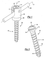
- an exemplary multi-axial bone fixation device 100 is illustrated as assembled with a spinal connecting element 109.
- the connecting element 109 is preferably in the form of a rod or bar or other elongated element.
- the connecting element 109 is illustrated as straight, it will be appreciated that the connecting element 109 preferably is curved and preferably has a curvature following, for example, the natural curvature of the spine.
- the bone fixation device 100 can generally include a bone fastener 102, a receiver 104, a hollow retaining member or sleeve 106, an annular element 140 and first and second retention elements 160, 150 shown in the form of split rings. Additional views of these components are illustrated in FIGS. 3A-7 and 9-10C .
- the bone fastener 102 includes a head 110 and a bone-engaging elongated portion 114 that preferably includes ridges, threads or other anchoring formations 116 along at least a portion of its length.
- the elongated portion 114 includes one or more cutting flutes 118 at its distal end.
- the head 110 of the bone fastener 102 defines a first circumferential groove 108 for at least partially receiving the first retention element 160.
- the head 110 includes a protrusion 119 having an internal driver-engagement surface 112 for engaging a conventional or other insertion tool (not shown).
- the engagement surface 112 preferably includes straight or curved drive faces. In the exemplary illustration of FIG. 2 , a five-lobe (pentalobe) engagement surface 112 is shown for use with an insertion tool having complementary driver surfaces.
- the receiver 104 defines an axial opening comprising an upper opening 105 and a lower opening 103 along a longitudinal axis A.
- the receiver 104 also includes an upper portion 121 comprising two arms 120 and defining a U-shaped transverse opening 101 along a transverse axis B.
- Each of the arms 120 defines inner engagement formations 128, such as threads, ridges, or grooves.
- the transverse opening 101 can be configured to receive a connecting element, such as the connecting element 109 shown in FIG. 1 .
- the receiver 104 includes a radially compressible lower portion 123 in the form of a socket defined by a plurality of spaced apart elongated elements or fingers 124.
- Each elongated element 124 includes an outward flange 126 directed radially away from the lower opening 103.
- the elongated elements 124 preferably are resiliently deflected inward toward the longitudinal axis A for receiving the hollow member 106.
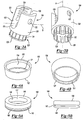
- the hollow member 106 includes an annular upper face 130, an annular lower face 132, and a peripheral wall 134 between the upper and lower faces 130, 132.
- the peripheral wall 134 is preferably tapered from the upper face 130 to the lower face 132, and defines an inner step or notch or other circumferential discontinuity 131.
- the hollow member 106 is insertably arranged around the compressible lower portion 123 such that the flanges 126 engage the discontinuity 131 and the elongated members 124 are urged radially inwards securing the hollow member 106 over the receiver 104 in a snap-fit or other engagement.
- the annular member 140 includes a peripheral or side wall 144 between upper and lower surfaces 146, 148.
- the peripheral wall 144 defines an opening 117 through the annular member 140.
- the annular member 140 preferably defines a second outer circumferential groove 142 on the peripheral wall 144 for at least partially receiving the second retention element 150.
- an exemplary procedure for assembling the multi-axial fixation device 100 includes assembling the first retention element 160 in the first circumferential groove 108 of the head 110 of the bone fastener 102, as shown in FIG. 8B , and inserting the bone fastener 102 from the lower portion 123 of the receiver 104 into the lower opening 103, as shown in FIG. 8C .
- the elongated elements 124 in their relaxed states cooperate to define an opening 103 larger than the diameter of the head 110.
- the hollow member 106 is preferably pushed over the lower portion 123 until the flanges 126 of the elongated elements 124 snap into the discontinuity 131 radially compressing the lower portion 123.
- a major diameter D of the head 110 exceeds a minor diameter "d" of the receiver 104.
- the minor diameter corresponds to the engagement formations 128.
- the fastener 102 angulates relative to the first longitudinal axis A of the receiver 104, as shown in FIG. 8D in phantom lines.
- the first retention element 160 provides frictional resistance to rotation of the bone fastener 102 relative to the receiver 104.
- the second retention element 150 is assembled in the second circumferential groove 142 of the annular element 140, which is inserted from the upper portion 121 of the receiver 104 and positioned to contact the head 110 of the bone fastener 102, as shown in FIG. 8D .
- the annular member 140 is seated around the protrusion 119 of the head 110 of the bone fastener 102, such that the protrusion 119 is inserted in the opening 117 defined by the peripheral wall 144.
- the second retention element 150 retains the annular member 140 in the receiver 104 and is supported between the second circumferential groove 142 and a notch 170 defined in an abutting inner surface of the receiver 104, as shown in FIGS. 10B and 10C .
- the connecting element 109 is inserted along the transverse axis B in the transverse opening 101 of the receiver 104.
- a securing or locking member 113 in the form of a set screw or other plug, for example, is inserted through the upper opening 105 of the receiver 104.
- the securing member 113 preferably includes engagement formations 111 complimentary to the engagement formations 128 of the receiver 104, and a driver-receiving inner surface 107.
- the engagement formations 111 preferably comprise a helical flange, for example.
- a driver is preferably coupled to the driver- receiving surface 107 and rotated to drive the securing member 113 against the connecting element 109, thereby transmitting compression through the annular element 140 to the head 110 of the bone fastener 102 and securing the bone fastener 102 in a preselected angulation position.
- the multi-axial bone fixation device 100 is preferably used with bone fasteners 102 having different sizes or shapes, or of different types, with or without flutes 118 or other cutting ridges.
- the extent and/or type of anchoring formations 116 can be varied, as well as the size and geometry of the head 110, etc.
- the present teachings allow quick loading of the bone fastener 102 from the lower portion 123 of the receiver and still maintain a high degree of angulation similar to top-loading bone fasteners. Further, the present teachings allow a major diameter D of the head of the bone fastener 102 to exceed a minor diameter d that is associated with the engagement formations 128 for the securing element 113. Thus the present teaching can prevent bone fastener back out.
Landscapes
- Health & Medical Sciences (AREA)
- Orthopedic Medicine & Surgery (AREA)
- Life Sciences & Earth Sciences (AREA)
- Neurology (AREA)
- Surgery (AREA)
- Heart & Thoracic Surgery (AREA)
- Engineering & Computer Science (AREA)
- Biomedical Technology (AREA)
- Nuclear Medicine, Radiotherapy & Molecular Imaging (AREA)
- Medical Informatics (AREA)
- Molecular Biology (AREA)
- Animal Behavior & Ethology (AREA)
- General Health & Medical Sciences (AREA)
- Public Health (AREA)
- Veterinary Medicine (AREA)
- Surgical Instruments (AREA)
- Prostheses (AREA)
Claims (12)
- Dispositif de fixation d'os multiaxial, comprenant :un récepteur (104) définissant une ouverture axiale le long d'un axe longitudinal (A), le récepteur (104) ayant des première et seconde parties (121, 123) le long de l'axe longitudinal (A), la seconde partie (123) étant radialement compressible ;un élément de fixation d'os (102) ayant une tête (110), la tête (110) pouvant être insérée dans l'ouverture axiale dans un sens allant de la seconde partie (123) vers la première partie (121) ;un élément creux (106) reçu autour de la seconde partie (123), l'élément creux (106) comprimant la seconde partie (123) et retenant la tête (110) tout en permettant l'angulation de l'élément de fixation (102) par rapport à l'axe longitudinal (A) et une première bague de retenue (160) dans une première rainure circonférentielle (108) de la tête (110) de l'élément de fixation (102), la première bague de retenue (160) fournissant une résistance par frottement à la rotation et maintenant une position de l'élément de fixation (102) par rapport au récepteur (104) avant l'implantation,dans lequel la seconde partie (123) comprend des doigts flexibles (124) comprenant des brides extérieures (126) et l'élément creux (106) comprend une discontinuité (131), discontinuité dans laquelle les brides des doigts peuvent s'encliqueter.
- Dispositif selon la revendication 1, dans lequel l'élément creux comprend une surface intérieure conique.
- Dispositif selon la revendication 1, dans lequel la tête (110) comprend une rainure circonférentielle (108), la première bague étant au moins partiellement disposée dans la rainure circonférentielle (108).
- Dispositif selon la revendication 1, comprenant en outre un élément annulaire (140) pouvant être inséré dans l'ouverture axiale dans un sens allant de la première partie (121) vers la seconde partie (123) et positionné en contact avec la tête (110) de l'élément de fixation d'os (102).
- Dispositif selon la revendication 4, dans lequel la tête (110) de l'élément de fixation d'os (102) comprend une surface interne d'engagement de dispositif d'entraînement (112).
- Dispositif selon la revendication 4, comprenant en outre une seconde bague supportée par l'élément annulaire (140), dans lequel la seconde bague fixe l'élément annulaire (140) à l'intérieur de l'ouverture axiale du récepteur (104).
- Dispositif selon la revendication 6, comprenant en outre un élément fileté, l'élément fileté étant reçu par vissage dans la première partie (121) du récepteur (104), l'élément fileté maintenant l'élément de fixation (102) dans un angle fixe par rapport à l'ouverture axiale.
- Dispositif selon la revendication 7, dans lequel l'élément fileté vient en contact avec un élément allongé reçu dans une ouverture transversale (101) du récepteur (104) entre l'élément fileté et l'élément annulaire (140).
- Dispositif selon la revendication 1, dans lequel la tête (110) de l'élément de fixation d'os (102) comprend une surface interne d'engagement de dispositif d'entraînement (112).
- Dispositif selon la revendication 1, dans lequel la seconde partie (123) comprend une pluralité d'éléments espacés (124).
- Dispositif selon la revendication 10, dans lequel chacun des éléments espacés (124) comprend une bride extérieure (126) s'étendant à proximité d'une extrémité distale de ceux-ci.
- Dispositif selon la revendication 11, dans lequel l'élément creux (106) comprend une discontinuité circonférentielle intérieure (131) s'engageant les brides extérieures (126) des éléments espacés (124).
Applications Claiming Priority (2)
| Application Number | Priority Date | Filing Date | Title |
|---|---|---|---|
| US11/594,316 US7699876B2 (en) | 2006-11-08 | 2006-11-08 | Multi-axial bone fixation apparatus |
| PCT/US2007/023423 WO2008057551A2 (fr) | 2006-11-08 | 2007-11-07 | Dispositif de fixation d'os à axes multiples |
Publications (2)
| Publication Number | Publication Date |
|---|---|
| EP2097025A2 EP2097025A2 (fr) | 2009-09-09 |
| EP2097025B1 true EP2097025B1 (fr) | 2015-07-22 |
Family
ID=39205293
Family Applications (1)
| Application Number | Title | Priority Date | Filing Date |
|---|---|---|---|
| EP07861779.2A Not-in-force EP2097025B1 (fr) | 2006-11-08 | 2007-11-07 | Dispositif de fixation d'os à axes multiples |
Country Status (3)
| Country | Link |
|---|---|
| US (1) | US7699876B2 (fr) |
| EP (1) | EP2097025B1 (fr) |
| WO (1) | WO2008057551A2 (fr) |
Families Citing this family (141)
| Publication number | Priority date | Publication date | Assignee | Title |
|---|---|---|---|---|
| US7833250B2 (en) | 2004-11-10 | 2010-11-16 | Jackson Roger P | Polyaxial bone screw with helically wound capture connection |
| US8353932B2 (en) | 2005-09-30 | 2013-01-15 | Jackson Roger P | Polyaxial bone anchor assembly with one-piece closure, pressure insert and plastic elongate member |
| US10729469B2 (en) | 2006-01-09 | 2020-08-04 | Roger P. Jackson | Flexible spinal stabilization assembly with spacer having off-axis core member |
| US7862587B2 (en) | 2004-02-27 | 2011-01-04 | Jackson Roger P | Dynamic stabilization assemblies, tool set and method |
| US8292926B2 (en) | 2005-09-30 | 2012-10-23 | Jackson Roger P | Dynamic stabilization connecting member with elastic core and outer sleeve |
| US10258382B2 (en) | 2007-01-18 | 2019-04-16 | Roger P. Jackson | Rod-cord dynamic connection assemblies with slidable bone anchor attachment members along the cord |
| WO2006052796A2 (fr) | 2004-11-10 | 2006-05-18 | Jackson Roger P | Guide helicoidal et rebord de glissement comportant des prolongements cassables |
| US8876868B2 (en) | 2002-09-06 | 2014-11-04 | Roger P. Jackson | Helical guide and advancement flange with radially loaded lip |
| US6716214B1 (en) | 2003-06-18 | 2004-04-06 | Roger P. Jackson | Polyaxial bone screw with spline capture connection |
| US7621918B2 (en) | 2004-11-23 | 2009-11-24 | Jackson Roger P | Spinal fixation tool set and method |
| US7377923B2 (en) | 2003-05-22 | 2008-05-27 | Alphatec Spine, Inc. | Variable angle spinal screw assembly |
| US7967850B2 (en) | 2003-06-18 | 2011-06-28 | Jackson Roger P | Polyaxial bone anchor with helical capture connection, insert and dual locking assembly |
| US7776067B2 (en) | 2005-05-27 | 2010-08-17 | Jackson Roger P | Polyaxial bone screw with shank articulation pressure insert and method |
| US20110040338A1 (en) * | 2003-08-28 | 2011-02-17 | Jackson Roger P | Polyaxial bone anchor having an open retainer with conical, cylindrical or curvate capture |
| US7766915B2 (en) | 2004-02-27 | 2010-08-03 | Jackson Roger P | Dynamic fixation assemblies with inner core and outer coil-like member |
| US8137386B2 (en) | 2003-08-28 | 2012-03-20 | Jackson Roger P | Polyaxial bone screw apparatus |
| US8814911B2 (en) | 2003-06-18 | 2014-08-26 | Roger P. Jackson | Polyaxial bone screw with cam connection and lock and release insert |
| US8398682B2 (en) | 2003-06-18 | 2013-03-19 | Roger P. Jackson | Polyaxial bone screw assembly |
| US8377102B2 (en) | 2003-06-18 | 2013-02-19 | Roger P. Jackson | Polyaxial bone anchor with spline capture connection and lower pressure insert |
| US8936623B2 (en) | 2003-06-18 | 2015-01-20 | Roger P. Jackson | Polyaxial bone screw assembly |
| US11419642B2 (en) | 2003-12-16 | 2022-08-23 | Medos International Sarl | Percutaneous access devices and bone anchor assemblies |
| US7179261B2 (en) | 2003-12-16 | 2007-02-20 | Depuy Spine, Inc. | Percutaneous access devices and bone anchor assemblies |
| US7527638B2 (en) | 2003-12-16 | 2009-05-05 | Depuy Spine, Inc. | Methods and devices for minimally invasive spinal fixation element placement |
| US7160300B2 (en) | 2004-02-27 | 2007-01-09 | Jackson Roger P | Orthopedic implant rod reduction tool set and method |
| US11241261B2 (en) | 2005-09-30 | 2022-02-08 | Roger P Jackson | Apparatus and method for soft spinal stabilization using a tensionable cord and releasable end structure |
| US8152810B2 (en) | 2004-11-23 | 2012-04-10 | Jackson Roger P | Spinal fixation tool set and method |
| JP2007525274A (ja) | 2004-02-27 | 2007-09-06 | ロジャー・ピー・ジャクソン | 整形外科インプラントロッド整復器具セット及び方法 |
| WO2005094707A2 (fr) * | 2004-03-26 | 2005-10-13 | Smith & Nephew, Inc. | Procedes de traitement des fractures femorales et dispositifs de fractures femorales |
| US7651502B2 (en) | 2004-09-24 | 2010-01-26 | Jackson Roger P | Spinal fixation tool set and method for rod reduction and fastener insertion |
| WO2006047555A2 (fr) * | 2004-10-25 | 2006-05-04 | Alphaspine, Inc. | Systemes de fixation osseuse et procedes d'assemblage et/ou d'installation desdits systemes |
| US8926672B2 (en) | 2004-11-10 | 2015-01-06 | Roger P. Jackson | Splay control closure for open bone anchor |
| US8308782B2 (en) | 2004-11-23 | 2012-11-13 | Jackson Roger P | Bone anchors with longitudinal connecting member engaging inserts and closures for fixation and optional angulation |
| WO2006057837A1 (fr) | 2004-11-23 | 2006-06-01 | Jackson Roger P | Structure d'accrochage pour outil de fixation spinale |
| US9216041B2 (en) | 2009-06-15 | 2015-12-22 | Roger P. Jackson | Spinal connecting members with tensioned cords and rigid sleeves for engaging compression inserts |
| US9980753B2 (en) | 2009-06-15 | 2018-05-29 | Roger P Jackson | pivotal anchor with snap-in-place insert having rotation blocking extensions |
| US9168069B2 (en) | 2009-06-15 | 2015-10-27 | Roger P. Jackson | Polyaxial bone anchor with pop-on shank and winged insert with lower skirt for engaging a friction fit retainer |
| US8444681B2 (en) | 2009-06-15 | 2013-05-21 | Roger P. Jackson | Polyaxial bone anchor with pop-on shank, friction fit retainer and winged insert |
| US7901437B2 (en) | 2007-01-26 | 2011-03-08 | Jackson Roger P | Dynamic stabilization member with molded connection |
| US10076361B2 (en) | 2005-02-22 | 2018-09-18 | Roger P. Jackson | Polyaxial bone screw with spherical capture, compression and alignment and retention structures |
| US7955358B2 (en) | 2005-09-19 | 2011-06-07 | Albert Todd J | Bone screw apparatus, system and method |
| US12357348B2 (en) | 2005-09-30 | 2025-07-15 | Roger P. Jackson | Method of assembling a pivotal bone anchor assembly with press-in-place insert |
| US8105368B2 (en) | 2005-09-30 | 2012-01-31 | Jackson Roger P | Dynamic stabilization connecting member with slitted core and outer sleeve |
| US7833252B2 (en) * | 2006-01-27 | 2010-11-16 | Warsaw Orthopedic, Inc. | Pivoting joints for spinal implants including designed resistance to motion and methods of use |
| US8057519B2 (en) | 2006-01-27 | 2011-11-15 | Warsaw Orthopedic, Inc. | Multi-axial screw assembly |
| US7722652B2 (en) | 2006-01-27 | 2010-05-25 | Warsaw Orthopedic, Inc. | Pivoting joints for spinal implants including designed resistance to motion and methods of use |
| WO2008008511A2 (fr) * | 2006-07-14 | 2008-01-17 | Laszlo Garamszegi | Ensemble de vis pédiculaire avec siège de surface incliné |
| JP2010512178A (ja) | 2006-12-08 | 2010-04-22 | ロジャー・ピー・ジャクソン | 動的脊椎インプラントのためのツールシステム |
| US8475498B2 (en) | 2007-01-18 | 2013-07-02 | Roger P. Jackson | Dynamic stabilization connecting member with cord connection |
| US8366745B2 (en) | 2007-05-01 | 2013-02-05 | Jackson Roger P | Dynamic stabilization assembly having pre-compressed spacers with differential displacements |
| US10383660B2 (en) | 2007-05-01 | 2019-08-20 | Roger P. Jackson | Soft stabilization assemblies with pretensioned cords |
| DE602007007758D1 (de) | 2007-07-31 | 2010-08-26 | Biedermann Motech Gmbh | Knochenverankerungsvorrichtung |
| US20090069852A1 (en) * | 2007-09-06 | 2009-03-12 | Warsaw Orthopedic, Inc. | Multi-Axial Bone Anchor Assembly |
| US12471958B2 (en) | 2007-09-17 | 2025-11-18 | Roger P. Jackson | Polyaxial pedicle screw assembly with cannulated screw shank having an internal drive socket surrounded by a planar top end surface |
| US20090082812A1 (en) * | 2007-09-21 | 2009-03-26 | Lewis Trevor K | Provisional locking pedicle screw system and method |
| US8007522B2 (en) | 2008-02-04 | 2011-08-30 | Depuy Spine, Inc. | Methods for correction of spinal deformities |
| WO2010147639A1 (fr) | 2008-08-01 | 2010-12-23 | Jackson Roger P | Élément longitudinal de liaison avec cordons tendus gainés |
| JP2010099293A (ja) * | 2008-10-24 | 2010-05-06 | Japan Medical Materials Corp | 脊椎固定用骨アンカーユニット及び脊椎固定用骨アンカーユニットの製造方法 |
| US8603145B2 (en) * | 2008-12-16 | 2013-12-10 | Zimmer Spine, Inc. | Coaxially lockable poly-axial bone fastener assemblies |
| ES2375879T3 (es) * | 2008-12-23 | 2012-03-07 | Biedermann Motech Gmbh | Zona de recepción de una varilla para acoplar la varilla en un elemento de anclaje óseo y dispositivo de anclaje óseo con dicha zona de recepción. |
| EP2204129B1 (fr) | 2008-12-30 | 2011-11-30 | Biedermann Motech GmbH | Pièce de réception pour recevoir une tige pour coupler la tige sur un élément d'ancrage d'os et dispositif d'ancrage d'os avec une telle pièce de réception |
| FR2942951B1 (fr) * | 2009-03-12 | 2012-03-30 | Euros Sa | Implant rachidien a liaison rotule verrouillable |
| US8998959B2 (en) | 2009-06-15 | 2015-04-07 | Roger P Jackson | Polyaxial bone anchors with pop-on shank, fully constrained friction fit retainer and lock and release insert |
| EP2753252A1 (fr) | 2009-06-15 | 2014-07-16 | Jackson, Roger P. | Ancrage osseux polyaxial avec tige fixée par pression et élément de retenue à ajustement serré doté d'un verrou de bordure discret |
| US9668771B2 (en) | 2009-06-15 | 2017-06-06 | Roger P Jackson | Soft stabilization assemblies with off-set connector |
| US11229457B2 (en) | 2009-06-15 | 2022-01-25 | Roger P. Jackson | Pivotal bone anchor assembly with insert tool deployment |
| WO2013043218A1 (fr) | 2009-06-15 | 2013-03-28 | Jackson Roger P | Dispositif d'ancrage osseux polyaxial doté d'une tige à enclenchement par pression et insert à ailettes à pince de compression à ajustement par friction |
| ES2496178T3 (es) * | 2009-08-20 | 2014-09-18 | Biedermann Technologies Gmbh & Co. Kg | Dispositivo de anclaje de hueso |
| AU2010303934B2 (en) | 2009-10-05 | 2014-03-27 | Roger P. Jackson | Polyaxial bone anchor with non-pivotable retainer and pop-on shank, some with friction fit |
| US20110106181A1 (en) * | 2009-10-30 | 2011-05-05 | Warsaw Orthopedic, Inc. | Adjustable saddle for a bone anchor |
| US8449578B2 (en) * | 2009-11-09 | 2013-05-28 | Ebi, Llc | Multiplanar bone anchor system |
| US9044272B2 (en) | 2009-11-09 | 2015-06-02 | Ebi, Llc | Multiplanar bone anchor system |
| US20110202094A1 (en) * | 2009-11-11 | 2011-08-18 | Pereira Mario L | Trans-polyaxial screw |
| EP2384709B1 (fr) * | 2010-05-05 | 2012-09-05 | Biedermann Technologies GmbH & Co. KG | Pièce de réception destinée à recevoir une tige pour coupler la tige à un élément d'ancrage d'os, dispositif d'ancrage d'os, procédé et outil d'assemblage |
| US12383311B2 (en) | 2010-05-14 | 2025-08-12 | Roger P. Jackson | Pivotal bone anchor assembly and method for use thereof |
| WO2012030712A1 (fr) * | 2010-08-30 | 2012-03-08 | Zimmer Spine, Inc. | Vis pédiculaire polyaxiale |
| JP2013540468A (ja) | 2010-09-08 | 2013-11-07 | ロジャー・ピー・ジャクソン | 弾性部および非弾性部を有する動的固定化部材 |
| JP2013545527A (ja) | 2010-11-02 | 2013-12-26 | ロジャー・ピー・ジャクソン | ポップオン式シャンクと枢動可能な保持部とを有する多軸の骨アンカー |
| ES2534940T3 (es) | 2010-12-10 | 2015-04-30 | Biedermann Technologies Gmbh & Co. Kg | Pieza receptora para recibir una varilla con el fin de acoplarla a un elemento de anclaje de hueso, y elemento de anclaje de hueso con una pieza receptora de este tipo |
| EP2462887B1 (fr) * | 2010-12-10 | 2012-07-18 | Biedermann Technologies GmbH & Co. KG | Dispositif d'ancrage d'os |
| US8992579B1 (en) | 2011-03-08 | 2015-03-31 | Nuvasive, Inc. | Lateral fixation constructs and related methods |
| WO2012128825A1 (fr) | 2011-03-24 | 2012-09-27 | Jackson Roger P | Ancrage osseux polyaxial avec articulation composée et tige enclipsable |
| US9295497B2 (en) | 2011-08-31 | 2016-03-29 | Biomet Manufacturing, Llc | Patient-specific sacroiliac and pedicle guides |
| US9066734B2 (en) | 2011-08-31 | 2015-06-30 | Biomet Manufacturing, Llc | Patient-specific sacroiliac guides and associated methods |
| EP2574297B1 (fr) | 2011-09-30 | 2015-11-11 | Biedermann Technologies GmbH & Co. KG | Dispositif d'ancrage d'os et outil fonctionnant avec un tel dispositif d'ancrage d'os |
| JP2014533136A (ja) | 2011-10-05 | 2014-12-11 | マーク・エイ・ドッドソン | モジュール開創器および関連する方法 |
| US8663291B2 (en) | 2011-10-28 | 2014-03-04 | Ortho Innovations, Llc | Top loading polyaxial ball and socket fastener |
| US8911479B2 (en) | 2012-01-10 | 2014-12-16 | Roger P. Jackson | Multi-start closures for open implants |
| US9060815B1 (en) | 2012-03-08 | 2015-06-23 | Nuvasive, Inc. | Systems and methods for performing spine surgery |
| ES2552987T3 (es) * | 2012-07-03 | 2015-12-03 | Biedermann Technologies Gmbh & Co. Kg | Dispositivo de anclaje de hueso poliaxial |
| EP2687171B1 (fr) | 2012-07-18 | 2015-04-22 | Biedermann Technologies GmbH & Co. KG | Dispositif d'ancrage d'os polyaxial |
| US9782204B2 (en) | 2012-09-28 | 2017-10-10 | Medos International Sarl | Bone anchor assemblies |
| US8911478B2 (en) | 2012-11-21 | 2014-12-16 | Roger P. Jackson | Splay control closure for open bone anchor |
| US10058354B2 (en) | 2013-01-28 | 2018-08-28 | Roger P. Jackson | Pivotal bone anchor assembly with frictional shank head seating surfaces |
| US8852239B2 (en) | 2013-02-15 | 2014-10-07 | Roger P Jackson | Sagittal angle screw with integral shank and receiver |
| US9259247B2 (en) | 2013-03-14 | 2016-02-16 | Medos International Sarl | Locking compression members for use with bone anchor assemblies and methods |
| US20140277203A1 (en) | 2013-03-14 | 2014-09-18 | Ebi, Llc | Torque multiplier, limiter, and counter-torque combinations and methods |
| US20140277153A1 (en) | 2013-03-14 | 2014-09-18 | DePuy Synthes Products, LLC | Bone Anchor Assemblies and Methods With Improved Locking |
| US9724145B2 (en) | 2013-03-14 | 2017-08-08 | Medos International Sarl | Bone anchor assemblies with multiple component bottom loading bone anchors |
| US10342582B2 (en) | 2013-03-14 | 2019-07-09 | DePuy Synthes Products, Inc. | Bone anchor assemblies and methods with improved locking |
| US9775660B2 (en) | 2013-03-14 | 2017-10-03 | DePuy Synthes Products, Inc. | Bottom-loading bone anchor assemblies and methods |
| EP2851021B1 (fr) | 2013-09-19 | 2016-12-14 | Biedermann Technologies GmbH & Co. KG | Ensemble de couplage d'une tige à un élément d'ancrage osseux, dispositif d'ancrage osseux polyaxial et dispositif de stabilisation modulaire |
| US9987047B2 (en) | 2013-10-07 | 2018-06-05 | Spine Wave, Inc. | Translating polyaxial screw |
| US9517089B1 (en) | 2013-10-08 | 2016-12-13 | Nuvasive, Inc. | Bone anchor with offset rod connector |
| US9566092B2 (en) | 2013-10-29 | 2017-02-14 | Roger P. Jackson | Cervical bone anchor with collet retainer and outer locking sleeve |
| US9717533B2 (en) | 2013-12-12 | 2017-08-01 | Roger P. Jackson | Bone anchor closure pivot-splay control flange form guide and advancement structure |
| US9498255B2 (en) * | 2013-12-31 | 2016-11-22 | Blackstone Medical, Inc. | Translational pedicle screw systems |
| US9451993B2 (en) | 2014-01-09 | 2016-09-27 | Roger P. Jackson | Bi-radial pop-on cervical bone anchor |
| US10064658B2 (en) | 2014-06-04 | 2018-09-04 | Roger P. Jackson | Polyaxial bone anchor with insert guides |
| US9597119B2 (en) | 2014-06-04 | 2017-03-21 | Roger P. Jackson | Polyaxial bone anchor with polymer sleeve |
| US10543021B2 (en) | 2014-10-21 | 2020-01-28 | Roger P. Jackson | Pivotal bone anchor assembly having an open ring positioner for a retainer |
| US9707013B2 (en) * | 2015-04-30 | 2017-07-18 | Warsaw Orthopedic, Inc. | Spinal implant system and methods of use |
| EP3120791B1 (fr) * | 2015-07-24 | 2017-11-22 | Biedermann Technologies GmbH & Co. KG | Dispositif d'ancrage osseux polyaxial et instrument destiné à être utilisé avec celui-ci |
| EP3973898B1 (fr) | 2016-02-26 | 2025-06-04 | Medos International Sarl | Élément de fixation d'os polyaxial |
| US9962192B2 (en) | 2016-03-17 | 2018-05-08 | Medos International Sarl | Multipoint fixation implants |
| EP3473198B1 (fr) * | 2016-08-04 | 2023-02-22 | Biedermann Technologies GmbH & Co. KG | Dispositif d'ancrage osseux polyaxial et système d'un instrument et dispositif d'ancrage osseux polyaxial |
| EP3287089B1 (fr) * | 2016-08-24 | 2019-07-24 | Biedermann Technologies GmbH & Co. KG | Dispositif d'ancrage osseux polyaxial et système d'un instrument et dispositif d'ancrage osseux polyaxial |
| US20190262044A1 (en) | 2016-09-16 | 2019-08-29 | Noah Roth | Bone anchor, instruments, and methods for use |
| US11026730B2 (en) * | 2017-05-10 | 2021-06-08 | Medos International Sarl | Bone anchors with drag features and related methods |
| US10258386B2 (en) * | 2017-06-15 | 2019-04-16 | Warsaw Orthopedic, Inc. | Spinal construct and method |
| US10610265B1 (en) | 2017-07-31 | 2020-04-07 | K2M, Inc. | Polyaxial bone screw with increased angulation |
| EP3476340B1 (fr) | 2017-10-25 | 2021-06-02 | Biedermann Technologies GmbH & Co. KG | Dispositif d'ancrage d'os polyaxial |
| US10695100B2 (en) * | 2017-12-15 | 2020-06-30 | Warsaw Orthopedic, Inc. | Spinal implant system and methods of use |
| US10695102B2 (en) | 2017-12-15 | 2020-06-30 | Warsaw Orthopedic, Inc. | Spinal implant system and methods of use |
| EP3536271B1 (fr) | 2018-03-06 | 2022-05-04 | Biedermann Technologies GmbH & Co. KG | Dispositif d'ancrage osseux polyaxial et système d'un instrument et dispositif d'ancrage osseux polyaxial |
| US10898232B2 (en) | 2018-03-20 | 2021-01-26 | Medos International Sàrl | Multipoint fixation implants and related methods |
| US10687858B2 (en) | 2018-11-08 | 2020-06-23 | Warsaw Orthopedic, Inc. | Spinal implant system and methods of use |
| US11234738B2 (en) | 2018-11-16 | 2022-02-01 | Roger P. Jackson | Pivotal bone anchor assembly having a deployable collet insert with internal pressure ring |
| US10918421B2 (en) * | 2019-05-07 | 2021-02-16 | Warsaw Orthopedic, Inc. | Spinal implant system and methods of use |
| WO2020237061A2 (fr) * | 2019-05-22 | 2020-11-26 | Nuvasive, Inc. | Vis de fixation postérieure de la colonne vertébrale |
| US11141197B2 (en) * | 2019-06-24 | 2021-10-12 | DePuy Synthes Products, Inc. | Polyaxial strut for external fixation |
| US11426210B2 (en) | 2019-09-25 | 2022-08-30 | Medos International Sàrl | Multipoint angled fixation implants for multiple screws and related methods |
| EP3821834B1 (fr) | 2019-11-14 | 2024-05-01 | Biedermann Technologies GmbH & Co. KG | Partie réceptrice de couplage d'une tige sur un ancrage osseux |
| JP7676711B2 (ja) | 2020-02-14 | 2025-05-15 | メドス・インターナショナル・エスエイアールエル | 統合された多点固定ねじ |
| US11376046B1 (en) | 2021-02-01 | 2022-07-05 | Warsaw Orthopedic, Inc. | Spinal implant system and method |
| AU2022230734A1 (en) | 2021-03-05 | 2023-10-19 | Medos International Sarl | Multi-feature polyaxial screw |
| US12127766B2 (en) | 2021-03-05 | 2024-10-29 | Medos International Sàrl | Selectively locking polyaxial screw |
| EP4074271B1 (fr) * | 2021-04-15 | 2024-09-11 | Biedermann Technologies GmbH & Co. KG | Dispositif d'ancrage d'os polyaxial |
| US11751915B2 (en) | 2021-07-09 | 2023-09-12 | Roger P. Jackson | Modular spinal fixation system with bottom-loaded universal shank heads |
| EP4129220B1 (fr) * | 2021-08-04 | 2024-07-03 | Biedermann Technologies GmbH & Co. KG | Dispositif de couplage d'une tige à un élément d'ancrage d'os et son procédé de fabrication |
| US12544111B2 (en) * | 2021-09-14 | 2026-02-10 | Agmspine, Sia | Polyaxial spinal screw |
| EP4570198B1 (fr) * | 2023-12-15 | 2026-04-15 | Biedermann Technologies GmbH & Co. KG | Dispositif de couplage pour coupler une tige à un ancrage osseux et système d'un tel dispositif de couplage et d'au moins deux ancrages osseux |
Family Cites Families (23)
| Publication number | Priority date | Publication date | Assignee | Title |
|---|---|---|---|---|
| DE3614101C1 (de) * | 1986-04-25 | 1987-10-22 | Juergen Prof Dr Med Harms | Pedikelschraube |
| US5669911A (en) * | 1995-04-13 | 1997-09-23 | Fastenetix, L.L.C. | Polyaxial pedicle screw |
| US5549608A (en) * | 1995-07-13 | 1996-08-27 | Fastenetix, L.L.C. | Advanced polyaxial locking screw and coupling element device for use with rod fixation apparatus |
| US5733285A (en) * | 1995-07-13 | 1998-03-31 | Fastenetix, Llc | Polyaxial locking mechanism |
| US5964760A (en) * | 1996-10-18 | 1999-10-12 | Spinal Innovations | Spinal implant fixation assembly |
| US5728098A (en) * | 1996-11-07 | 1998-03-17 | Sdgi Holdings, Inc. | Multi-angle bone screw assembly using shape-memory technology |
| DE59712497D1 (de) * | 1997-01-22 | 2005-12-29 | Synthes Ag | Vorrichtung zur verbindung eines langsträgers mit einer pedikelschraube |
| US6010503A (en) * | 1998-04-03 | 2000-01-04 | Spinal Innovations, Llc | Locking mechanism |
| EP1117336B1 (fr) * | 1998-09-29 | 2004-05-19 | SYNTHES AG Chur | Dispositif pour assembler un support longitudinal et un moyen de fixation d'os |
| US6273888B1 (en) * | 1999-05-28 | 2001-08-14 | Sdgi Holdings, Inc. | Device and method for selectively preventing the locking of a shape-memory alloy coupling system |
| US6254602B1 (en) | 1999-05-28 | 2001-07-03 | Sdgi Holdings, Inc. | Advanced coupling device using shape-memory technology |
| US6280442B1 (en) * | 1999-09-01 | 2001-08-28 | Sdgi Holdings, Inc. | Multi-axial bone screw assembly |
| US7066937B2 (en) * | 2002-02-13 | 2006-06-27 | Endius Incorporated | Apparatus for connecting a longitudinal member to a bone portion |
| WO2004089245A2 (fr) | 2003-04-04 | 2004-10-21 | Theken Surgical, Llc | Element d'ancrage osseux |
| AU2004266737B2 (en) | 2003-08-20 | 2010-05-13 | Warsaw Orthopedic, Inc. | Multi-axial orthopedic device and system, e.g. for spinal surgery |
| US20050080415A1 (en) * | 2003-10-14 | 2005-04-14 | Keyer Thomas R. | Polyaxial bone anchor and method of spinal fixation |
| US7090674B2 (en) | 2003-11-03 | 2006-08-15 | Spinal, Llc | Bone fixation system with low profile fastener |
| US20050251192A1 (en) | 2004-03-31 | 2005-11-10 | Shluzas Alan E | Access device having discrete visualization locations |
| US8475495B2 (en) * | 2004-04-08 | 2013-07-02 | Globus Medical | Polyaxial screw |
| US7491207B2 (en) * | 2004-04-12 | 2009-02-17 | Synthes Usa, Llc | Rod persuader |
| WO2006047555A2 (fr) | 2004-10-25 | 2006-05-04 | Alphaspine, Inc. | Systemes de fixation osseuse et procedes d'assemblage et/ou d'installation desdits systemes |
| US7674277B2 (en) | 2004-12-01 | 2010-03-09 | Warsaw Orthopedic, Inc. | Side-loading bone anchor |
| US20070118117A1 (en) * | 2005-10-20 | 2007-05-24 | Ebi, L.P. | Bone fixation assembly |
-
2006
- 2006-11-08 US US11/594,316 patent/US7699876B2/en active Active
-
2007
- 2007-11-07 WO PCT/US2007/023423 patent/WO2008057551A2/fr not_active Ceased
- 2007-11-07 EP EP07861779.2A patent/EP2097025B1/fr not_active Not-in-force
Also Published As
| Publication number | Publication date |
|---|---|
| EP2097025A2 (fr) | 2009-09-09 |
| WO2008057551A2 (fr) | 2008-05-15 |
| US20080108992A1 (en) | 2008-05-08 |
| US7699876B2 (en) | 2010-04-20 |
| WO2008057551A3 (fr) | 2008-07-03 |
Similar Documents
| Publication | Publication Date | Title |
|---|---|---|
| EP2097025B1 (fr) | Dispositif de fixation d'os à axes multiples | |
| US11793552B2 (en) | Receiving part for receiving a rod for coupling the rod to a bone anchoring element and a bone anchoring device with such a receiving part | |
| US9936979B2 (en) | Bone anchor with locking cap and method of spinal fixation | |
| EP2851021B1 (fr) | Ensemble de couplage d'une tige à un élément d'ancrage osseux, dispositif d'ancrage osseux polyaxial et dispositif de stabilisation modulaire | |
| US9603641B2 (en) | Device for osteosynthesis | |
| US9445847B2 (en) | Polyaxial bone anchoring device | |
| US6224598B1 (en) | Bone screw threaded plug closure with central set screw | |
| US6569164B1 (en) | Spinal osteosynthesis system for anterior fixation | |
| US8506609B2 (en) | Receiving part for receiving a rod for coupling the rod to a bone anchoring element and a bone anchoring device with such a receiving part | |
| EP2764840B1 (fr) | Ensemble de couplage d'une tige à un élément d'ancrage osseux et dispositif d'ancrage osseux avec un tel ensemble de couplage | |
| JP5613401B2 (ja) | ロッドを受けてそのロッドを骨固定要素に連結するための受け部、およびそのような受け部を有する骨固定装置 | |
| JP5957216B2 (ja) | 骨アンカー固定装置 | |
| EP1306058A2 (fr) | Plaque pour implantation chirurgicale | |
| US20040267264A1 (en) | Polyaxial bone screw | |
| JP7343717B2 (ja) | モジュール式引っ張り脊髄用ネジ | |
| EP2674123B1 (fr) | Dispositif d'ancrage d'os polyaxial | |
| JP2008502458A (ja) | 脊椎骨安定化システム用の固定システム | |
| US12070248B2 (en) | Polyaxial bone anchoring device and system including an instrument and a polyaxial bone anchoring device | |
| WO2010111470A1 (fr) | Ensemble vis à os multiaxial, à hauteur variable | |
| CN114052879B (zh) | 骨锚固装置 |
Legal Events
| Date | Code | Title | Description |
|---|---|---|---|
| PUAI | Public reference made under article 153(3) epc to a published international application that has entered the european phase |
Free format text: ORIGINAL CODE: 0009012 |
|
| 17P | Request for examination filed |
Effective date: 20090608 |
|
| AK | Designated contracting states |
Kind code of ref document: A2 Designated state(s): AT BE BG CH CY CZ DE DK EE ES FI FR GB GR HU IE IS IT LI LT LU LV MC MT NL PL PT RO SE SI SK TR |
|
| RAP1 | Party data changed (applicant data changed or rights of an application transferred) |
Owner name: EBI, LLC |
|
| DAX | Request for extension of the european patent (deleted) | ||
| 17Q | First examination report despatched |
Effective date: 20120615 |
|
| GRAP | Despatch of communication of intention to grant a patent |
Free format text: ORIGINAL CODE: EPIDOSNIGR1 |
|
| INTG | Intention to grant announced |
Effective date: 20150217 |
|
| GRAS | Grant fee paid |
Free format text: ORIGINAL CODE: EPIDOSNIGR3 |
|
| GRAA | (expected) grant |
Free format text: ORIGINAL CODE: 0009210 |
|
| AK | Designated contracting states |
Kind code of ref document: B1 Designated state(s): AT BE BG CH CY CZ DE DK EE ES FI FR GB GR HU IE IS IT LI LT LU LV MC MT NL PL PT RO SE SI SK TR |
|
| REG | Reference to a national code |
Ref country code: GB Ref legal event code: FG4D |
|
| REG | Reference to a national code |
Ref country code: CH Ref legal event code: EP |
|
| REG | Reference to a national code |
Ref country code: IE Ref legal event code: FG4D |
|
| REG | Reference to a national code |
Ref country code: AT Ref legal event code: REF Ref document number: 737419 Country of ref document: AT Kind code of ref document: T Effective date: 20150815 |
|
| REG | Reference to a national code |
Ref country code: DE Ref legal event code: R096 Ref document number: 602007042295 Country of ref document: DE |
|
| REG | Reference to a national code |
Ref country code: FR Ref legal event code: PLFP Year of fee payment: 9 |
|
| REG | Reference to a national code |
Ref country code: CH Ref legal event code: NV Representative=s name: OFFICE ERNEST T. FREYLINGER S.A., CH |
|
| REG | Reference to a national code |
Ref country code: AT Ref legal event code: MK05 Ref document number: 737419 Country of ref document: AT Kind code of ref document: T Effective date: 20150722 |
|
| REG | Reference to a national code |
Ref country code: LT Ref legal event code: MG4D |
|
| REG | Reference to a national code |
Ref country code: NL Ref legal event code: MP Effective date: 20150722 |
|
| PG25 | Lapsed in a contracting state [announced via postgrant information from national office to epo] |
Ref country code: LV Free format text: LAPSE BECAUSE OF FAILURE TO SUBMIT A TRANSLATION OF THE DESCRIPTION OR TO PAY THE FEE WITHIN THE PRESCRIBED TIME-LIMIT Effective date: 20150722 Ref country code: LT Free format text: LAPSE BECAUSE OF FAILURE TO SUBMIT A TRANSLATION OF THE DESCRIPTION OR TO PAY THE FEE WITHIN THE PRESCRIBED TIME-LIMIT Effective date: 20150722 Ref country code: GR Free format text: LAPSE BECAUSE OF FAILURE TO SUBMIT A TRANSLATION OF THE DESCRIPTION OR TO PAY THE FEE WITHIN THE PRESCRIBED TIME-LIMIT Effective date: 20151023 Ref country code: FI Free format text: LAPSE BECAUSE OF FAILURE TO SUBMIT A TRANSLATION OF THE DESCRIPTION OR TO PAY THE FEE WITHIN THE PRESCRIBED TIME-LIMIT Effective date: 20150722 |
|
| PG25 | Lapsed in a contracting state [announced via postgrant information from national office to epo] |
Ref country code: PL Free format text: LAPSE BECAUSE OF FAILURE TO SUBMIT A TRANSLATION OF THE DESCRIPTION OR TO PAY THE FEE WITHIN THE PRESCRIBED TIME-LIMIT Effective date: 20150722 Ref country code: IS Free format text: LAPSE BECAUSE OF FAILURE TO SUBMIT A TRANSLATION OF THE DESCRIPTION OR TO PAY THE FEE WITHIN THE PRESCRIBED TIME-LIMIT Effective date: 20151122 Ref country code: ES Free format text: LAPSE BECAUSE OF FAILURE TO SUBMIT A TRANSLATION OF THE DESCRIPTION OR TO PAY THE FEE WITHIN THE PRESCRIBED TIME-LIMIT Effective date: 20150722 Ref country code: SE Free format text: LAPSE BECAUSE OF FAILURE TO SUBMIT A TRANSLATION OF THE DESCRIPTION OR TO PAY THE FEE WITHIN THE PRESCRIBED TIME-LIMIT Effective date: 20150722 Ref country code: AT Free format text: LAPSE BECAUSE OF FAILURE TO SUBMIT A TRANSLATION OF THE DESCRIPTION OR TO PAY THE FEE WITHIN THE PRESCRIBED TIME-LIMIT Effective date: 20150722 Ref country code: PT Free format text: LAPSE BECAUSE OF FAILURE TO SUBMIT A TRANSLATION OF THE DESCRIPTION OR TO PAY THE FEE WITHIN THE PRESCRIBED TIME-LIMIT Effective date: 20151123 |
|
| REG | Reference to a national code |
Ref country code: DE Ref legal event code: R097 Ref document number: 602007042295 Country of ref document: DE |
|
| PG25 | Lapsed in a contracting state [announced via postgrant information from national office to epo] |
Ref country code: EE Free format text: LAPSE BECAUSE OF FAILURE TO SUBMIT A TRANSLATION OF THE DESCRIPTION OR TO PAY THE FEE WITHIN THE PRESCRIBED TIME-LIMIT Effective date: 20150722 Ref country code: CZ Free format text: LAPSE BECAUSE OF FAILURE TO SUBMIT A TRANSLATION OF THE DESCRIPTION OR TO PAY THE FEE WITHIN THE PRESCRIBED TIME-LIMIT Effective date: 20150722 Ref country code: SK Free format text: LAPSE BECAUSE OF FAILURE TO SUBMIT A TRANSLATION OF THE DESCRIPTION OR TO PAY THE FEE WITHIN THE PRESCRIBED TIME-LIMIT Effective date: 20150722 Ref country code: IT Free format text: LAPSE BECAUSE OF FAILURE TO SUBMIT A TRANSLATION OF THE DESCRIPTION OR TO PAY THE FEE WITHIN THE PRESCRIBED TIME-LIMIT Effective date: 20150722 Ref country code: DK Free format text: LAPSE BECAUSE OF FAILURE TO SUBMIT A TRANSLATION OF THE DESCRIPTION OR TO PAY THE FEE WITHIN THE PRESCRIBED TIME-LIMIT Effective date: 20150722 |
|
| PLBE | No opposition filed within time limit |
Free format text: ORIGINAL CODE: 0009261 |
|
| STAA | Information on the status of an ep patent application or granted ep patent |
Free format text: STATUS: NO OPPOSITION FILED WITHIN TIME LIMIT |
|
| PG25 | Lapsed in a contracting state [announced via postgrant information from national office to epo] |
Ref country code: RO Free format text: LAPSE BECAUSE OF FAILURE TO SUBMIT A TRANSLATION OF THE DESCRIPTION OR TO PAY THE FEE WITHIN THE PRESCRIBED TIME-LIMIT Effective date: 20150722 |
|
| 26N | No opposition filed |
Effective date: 20160425 |
|
| PG25 | Lapsed in a contracting state [announced via postgrant information from national office to epo] |
Ref country code: LU Free format text: LAPSE BECAUSE OF FAILURE TO SUBMIT A TRANSLATION OF THE DESCRIPTION OR TO PAY THE FEE WITHIN THE PRESCRIBED TIME-LIMIT Effective date: 20151107 Ref country code: MC Free format text: LAPSE BECAUSE OF FAILURE TO SUBMIT A TRANSLATION OF THE DESCRIPTION OR TO PAY THE FEE WITHIN THE PRESCRIBED TIME-LIMIT Effective date: 20150722 |
|
| PG25 | Lapsed in a contracting state [announced via postgrant information from national office to epo] |
Ref country code: SI Free format text: LAPSE BECAUSE OF FAILURE TO SUBMIT A TRANSLATION OF THE DESCRIPTION OR TO PAY THE FEE WITHIN THE PRESCRIBED TIME-LIMIT Effective date: 20150722 |
|
| REG | Reference to a national code |
Ref country code: FR Ref legal event code: PLFP Year of fee payment: 10 |
|
| PG25 | Lapsed in a contracting state [announced via postgrant information from national office to epo] |
Ref country code: BE Free format text: LAPSE BECAUSE OF FAILURE TO SUBMIT A TRANSLATION OF THE DESCRIPTION OR TO PAY THE FEE WITHIN THE PRESCRIBED TIME-LIMIT Effective date: 20150722 |
|
| PG25 | Lapsed in a contracting state [announced via postgrant information from national office to epo] |
Ref country code: BG Free format text: LAPSE BECAUSE OF FAILURE TO SUBMIT A TRANSLATION OF THE DESCRIPTION OR TO PAY THE FEE WITHIN THE PRESCRIBED TIME-LIMIT Effective date: 20150722 Ref country code: HU Free format text: LAPSE BECAUSE OF FAILURE TO SUBMIT A TRANSLATION OF THE DESCRIPTION OR TO PAY THE FEE WITHIN THE PRESCRIBED TIME-LIMIT; INVALID AB INITIO Effective date: 20071107 |
|
| PG25 | Lapsed in a contracting state [announced via postgrant information from national office to epo] |
Ref country code: NL Free format text: LAPSE BECAUSE OF FAILURE TO SUBMIT A TRANSLATION OF THE DESCRIPTION OR TO PAY THE FEE WITHIN THE PRESCRIBED TIME-LIMIT Effective date: 20150722 Ref country code: CY Free format text: LAPSE BECAUSE OF FAILURE TO SUBMIT A TRANSLATION OF THE DESCRIPTION OR TO PAY THE FEE WITHIN THE PRESCRIBED TIME-LIMIT Effective date: 20150722 |
|
| PG25 | Lapsed in a contracting state [announced via postgrant information from national office to epo] |
Ref country code: MT Free format text: LAPSE BECAUSE OF FAILURE TO SUBMIT A TRANSLATION OF THE DESCRIPTION OR TO PAY THE FEE WITHIN THE PRESCRIBED TIME-LIMIT Effective date: 20150722 Ref country code: TR Free format text: LAPSE BECAUSE OF FAILURE TO SUBMIT A TRANSLATION OF THE DESCRIPTION OR TO PAY THE FEE WITHIN THE PRESCRIBED TIME-LIMIT Effective date: 20150722 |
|
| REG | Reference to a national code |
Ref country code: FR Ref legal event code: PLFP Year of fee payment: 11 |
|
| REG | Reference to a national code |
Ref country code: CH Ref legal event code: NV Representative=s name: SCHNEIDER FELDMANN AG PATENT- UND MARKENANWAEL, CH Ref country code: CH Ref legal event code: PUE Owner name: ZIMMER BIOMET SPINE, INC., US Free format text: FORMER OWNER: EBI, LLC, US |
|
| REG | Reference to a national code |
Ref country code: GB Ref legal event code: 732E Free format text: REGISTERED BETWEEN 20171207 AND 20171213 |
|
| PGFP | Annual fee paid to national office [announced via postgrant information from national office to epo] |
Ref country code: FR Payment date: 20171012 Year of fee payment: 11 |
|
| PGFP | Annual fee paid to national office [announced via postgrant information from national office to epo] |
Ref country code: CH Payment date: 20171114 Year of fee payment: 11 Ref country code: IE Payment date: 20171109 Year of fee payment: 11 |
|
| REG | Reference to a national code |
Ref country code: FR Ref legal event code: TP Owner name: ZIMMER BIOMET SPINE, INC., US Effective date: 20180515 |
|
| REG | Reference to a national code |
Ref country code: CH Ref legal event code: PL |
|
| REG | Reference to a national code |
Ref country code: DE Ref legal event code: R082 Ref document number: 602007042295 Ref country code: DE Ref legal event code: R082 Ref document number: 602007042295 Country of ref document: DE Representative=s name: VENNER SHIPLEY LLP, CAMBRIDGE, GB |
|
| REG | Reference to a national code |
Ref country code: IE Ref legal event code: MM4A |
|
| PG25 | Lapsed in a contracting state [announced via postgrant information from national office to epo] |
Ref country code: CH Free format text: LAPSE BECAUSE OF NON-PAYMENT OF DUE FEES Effective date: 20181130 Ref country code: LI Free format text: LAPSE BECAUSE OF NON-PAYMENT OF DUE FEES Effective date: 20181130 |
|
| PG25 | Lapsed in a contracting state [announced via postgrant information from national office to epo] |
Ref country code: FR Free format text: LAPSE BECAUSE OF NON-PAYMENT OF DUE FEES Effective date: 20181130 Ref country code: IE Free format text: LAPSE BECAUSE OF NON-PAYMENT OF DUE FEES Effective date: 20181107 |
|
| REG | Reference to a national code |
Ref country code: DE Ref legal event code: R081 Ref document number: 602007042295 Country of ref document: DE Owner name: ZIMMER BIOMET SPINE, INC., BROOMFIELD, US Free format text: FORMER OWNER: EBI, LLC, PARSIPPANY, N.J., US Ref country code: DE Ref legal event code: R082 Ref document number: 602007042295 Country of ref document: DE Ref country code: DE Ref legal event code: R081 Ref document number: 602007042295 Country of ref document: DE Owner name: ZIMMER BIOMET SPINE, INC., WESTMINSTER, US Free format text: FORMER OWNER: EBI, LLC, PARSIPPANY, N.J., US |
|
| REG | Reference to a national code |
Ref country code: DE Ref legal event code: R081 Ref document number: 602007042295 Country of ref document: DE Owner name: ZIMMER BIOMET SPINE, INC., WESTMINSTER, US Free format text: FORMER OWNER: ZIMMER BIOMET SPINE, INC., BROOMFIELD, COL., US |
|
| PGFP | Annual fee paid to national office [announced via postgrant information from national office to epo] |
Ref country code: GB Payment date: 20201008 Year of fee payment: 14 |
|
| GBPC | Gb: european patent ceased through non-payment of renewal fee |
Effective date: 20211107 |
|
| PG25 | Lapsed in a contracting state [announced via postgrant information from national office to epo] |
Ref country code: GB Free format text: LAPSE BECAUSE OF NON-PAYMENT OF DUE FEES Effective date: 20211107 |
|
| PGFP | Annual fee paid to national office [announced via postgrant information from national office to epo] |
Ref country code: DE Payment date: 20220914 Year of fee payment: 16 |
|
| REG | Reference to a national code |
Ref country code: DE Ref legal event code: R119 Ref document number: 602007042295 Country of ref document: DE |
|
| PG25 | Lapsed in a contracting state [announced via postgrant information from national office to epo] |
Ref country code: DE Free format text: LAPSE BECAUSE OF NON-PAYMENT OF DUE FEES Effective date: 20240601 |
|
| PG25 | Lapsed in a contracting state [announced via postgrant information from national office to epo] |
Ref country code: DE Free format text: LAPSE BECAUSE OF NON-PAYMENT OF DUE FEES Effective date: 20240601 |