EP2097134B1 - Dispositif de neurostimulation biomimétique - Google Patents
Dispositif de neurostimulation biomimétique Download PDFInfo
- Publication number
- EP2097134B1 EP2097134B1 EP07859442.1A EP07859442A EP2097134B1 EP 2097134 B1 EP2097134 B1 EP 2097134B1 EP 07859442 A EP07859442 A EP 07859442A EP 2097134 B1 EP2097134 B1 EP 2097134B1
- Authority
- EP
- European Patent Office
- Prior art keywords
- signals
- region
- input
- neural
- output
- Prior art date
- Legal status (The legal status is an assumption and is not a legal conclusion. Google has not performed a legal analysis and makes no representation as to the accuracy of the status listed.)
- Not-in-force
Links
Images


Classifications
-
- A—HUMAN NECESSITIES
- A61—MEDICAL OR VETERINARY SCIENCE; HYGIENE
- A61N—ELECTROTHERAPY; MAGNETOTHERAPY; RADIATION THERAPY; ULTRASOUND THERAPY
- A61N1/00—Electrotherapy; Circuits therefor
- A61N1/18—Applying electric currents by contact electrodes
- A61N1/32—Applying electric currents by contact electrodes alternating or intermittent currents
- A61N1/36—Applying electric currents by contact electrodes alternating or intermittent currents for stimulation
- A61N1/3605—Implantable neurostimulators for stimulating central or peripheral nerve system
- A61N1/36128—Control systems
- A61N1/36135—Control systems using physiological parameters
- A61N1/36139—Control systems using physiological parameters with automatic adjustment
-
- A—HUMAN NECESSITIES
- A61—MEDICAL OR VETERINARY SCIENCE; HYGIENE
- A61N—ELECTROTHERAPY; MAGNETOTHERAPY; RADIATION THERAPY; ULTRASOUND THERAPY
- A61N1/00—Electrotherapy; Circuits therefor
- A61N1/18—Applying electric currents by contact electrodes
- A61N1/32—Applying electric currents by contact electrodes alternating or intermittent currents
- A61N1/36—Applying electric currents by contact electrodes alternating or intermittent currents for stimulation
- A61N1/36014—External stimulators, e.g. with patch electrodes
- A61N1/36025—External stimulators, e.g. with patch electrodes for treating a mental or cerebral condition
-
- A—HUMAN NECESSITIES
- A61—MEDICAL OR VETERINARY SCIENCE; HYGIENE
- A61N—ELECTROTHERAPY; MAGNETOTHERAPY; RADIATION THERAPY; ULTRASOUND THERAPY
- A61N1/00—Electrotherapy; Circuits therefor
- A61N1/02—Details
- A61N1/04—Electrodes
- A61N1/05—Electrodes for implantation or insertion into the body, e.g. heart electrode
- A61N1/0526—Head electrodes
- A61N1/0529—Electrodes for brain stimulation
- A61N1/0534—Electrodes for deep brain stimulation
-
- A—HUMAN NECESSITIES
- A61—MEDICAL OR VETERINARY SCIENCE; HYGIENE
- A61N—ELECTROTHERAPY; MAGNETOTHERAPY; RADIATION THERAPY; ULTRASOUND THERAPY
- A61N1/00—Electrotherapy; Circuits therefor
- A61N1/18—Applying electric currents by contact electrodes
- A61N1/32—Applying electric currents by contact electrodes alternating or intermittent currents
- A61N1/36—Applying electric currents by contact electrodes alternating or intermittent currents for stimulation
- A61N1/3605—Implantable neurostimulators for stimulating central or peripheral nerve system
- A61N1/3606—Implantable neurostimulators for stimulating central or peripheral nerve system adapted for a particular treatment
- A61N1/36067—Movement disorders, e.g. tremor or Parkinson disease
-
- A—HUMAN NECESSITIES
- A61—MEDICAL OR VETERINARY SCIENCE; HYGIENE
- A61N—ELECTROTHERAPY; MAGNETOTHERAPY; RADIATION THERAPY; ULTRASOUND THERAPY
- A61N1/00—Electrotherapy; Circuits therefor
- A61N1/18—Applying electric currents by contact electrodes
- A61N1/32—Applying electric currents by contact electrodes alternating or intermittent currents
- A61N1/36—Applying electric currents by contact electrodes alternating or intermittent currents for stimulation
- A61N1/36014—External stimulators, e.g. with patch electrodes
- A61N1/36021—External stimulators, e.g. with patch electrodes for treatment of pain
-
- A—HUMAN NECESSITIES
- A61—MEDICAL OR VETERINARY SCIENCE; HYGIENE
- A61N—ELECTROTHERAPY; MAGNETOTHERAPY; RADIATION THERAPY; ULTRASOUND THERAPY
- A61N1/00—Electrotherapy; Circuits therefor
- A61N1/18—Applying electric currents by contact electrodes
- A61N1/32—Applying electric currents by contact electrodes alternating or intermittent currents
- A61N1/36—Applying electric currents by contact electrodes alternating or intermittent currents for stimulation
- A61N1/3605—Implantable neurostimulators for stimulating central or peripheral nerve system
- A61N1/3606—Implantable neurostimulators for stimulating central or peripheral nerve system adapted for a particular treatment
- A61N1/36082—Cognitive or psychiatric applications, e.g. dementia or Alzheimer's disease
-
- A—HUMAN NECESSITIES
- A61—MEDICAL OR VETERINARY SCIENCE; HYGIENE
- A61N—ELECTROTHERAPY; MAGNETOTHERAPY; RADIATION THERAPY; ULTRASOUND THERAPY
- A61N2/00—Magnetotherapy
- A61N2/004—Magnetotherapy specially adapted for a specific therapy
- A61N2/006—Magnetotherapy specially adapted for a specific therapy for magnetic stimulation of nerve tissue
Definitions
- the present application relates to the field of biomimetic neurostimulation devices.
- An alternative treatment for neurological disorders is neurostimulation therapy.
- Such therapy applies electric or magnetic stimuli to neural tissues by means of external or implanted devices.
- Zu bioimetic neurostimulation device is described in Berger et al., "Brain Implantable Biomimetic Electronics as the next Era in Neural Prosthetics, "Proc. IEEE, Vol. 89, #7, July 2001 pp. 993-1012 .
- This document describes an electronic model of the input-output transformation by the hippocampus.
- Another such device is known from Song et al. "Physiologically plausible stochastic kernel models of spike train to spike train transformation", Proc. 28th IEEE, Vo. 1, Aug 2006, pp. 6129-6132 .
- a more adaptable and flexible device can be used as a prosthetic for compromised tissue and include at least one signal processing apparatus that includes a feed-forward path and a modulation path.
- the feed- forward path simulates neurological signal zu processing between regions afferent and efferent to a suspect region.
- the modulation path informs the feed-forward path responsive to signals received elsewhere.
- the modulation path can feed back signals even further efferent than an output of the feed-forward path.
- Disorders potentially treatable with this therapy include motor disorders, cognitive disorders, or injury. It is particularly hoped that such a more adaptive and flexible device would be useful in neurological disorders such as Parkinson's Disease.
- Other examples of neurological disorders potentially treatable with such a device include Multiple Sclerosis; epilepsy; pain; and more cognitive disorders such as Alzheimer's Disease, depression, bipolar disorder, Obsessive
- Compulsive Disorder and addiction; and possibly even obesity.
- the treatment may be used in rehabilitation therapy following stroke or traumatic brain injury.
- Fig. 1A is a schematic of a patient's head 101 including a biomimetic neurostimulation device 102 provided with an optional antenna 103 (shown schematically) for external communication.
- a biomimetic neurostimulation device 102 provided with an optional antenna 103 (shown schematically) for external communication.
- Other types of external communication might be possible, such as a lead connected to the outside of the patient's skull.
- the device 102 is shown inside the brain, but it might be placed in other neural pathways, such as in the spinal column.
- An optional external system 104 communicates with the device 102 via antenna 105.
- the external system 104 provides data to the device 102, for instance when a medical service provider detects progression of a disorder or from some sensor.
- the external system 104 may additionally or alternatively provide auxiliary processing or control for 102.
- Fig. 1B displays a schematic representation of the basal ganglia-thalamocortical motor circuits ( Y. Temel et al., Progress in Neurobiology volume 76, pages 393-413 (2005 )).
- This figure shows the cortex 150, substantia nigra pars compacta (SNc) 151, putamen 152, globus pallidus external segment (GPe) 153, thalamus 154, brain stem and spinal cord 155, subthalamic nucleus (STN) 156, and globus pallidus internal segment (GPi) 157.
- Excitatory connections are denoted by “+”, inhibitory connections are denoted by “-”, and modulatory connections are denoted by “m”.
- the physiological functions schematized in this circuit are affected in motor diseases like Parkinson's disease, essential tremor, and dystonia for example.
- the proposed biomimetic neurostimulation device is well adapted to correct for pathological signals in such brain circuits.
- Fig. 2 is a more detailed schematic of a subpart of a brain circuit as displayed in Fig. 1B .
- the depicted region of the neurological system exhibits signal flow predominantly in a single direction. Some regions of motor control are particularly likely to have flow of this sort. In general, the flow will proceed from an afferent (upstream) region to an efferent (downstream) region.
- the circuit's sub-part receives afferent signals I at its (synaptic) inputs 202 and produces neurological signals O at its (synaptic) outputs 203.
- Four lines are shown as inputs 202 and as outputs 203. Four is an arbitrary number.
- the modulating signals may be inhibitory 204 and/or excitatory 205 and in general comprise both feed-forward and feed-back signals. Both the afferent inputs and the modulatory signals are by nature non-stationary, so the output will be highly dynamic. Note that, as shown in Fig. 1B , bi-directional signal flow between regions (either direct or via larger circuits) is another general theme in neurological systems. The functioning of such circuits can be described in a similar way.
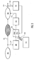
- Fig. 3 shows a schematic of a biomimetic neurostimulator, implanted in a brain or nerve pathway.
- the pathway includes three regions 306,307, and 308. Regions 306 and 308 are expected to remain healthy, while region 307 is either compromised or expected to become compromised.
- the primary flow of neural signals is expected to be in one direction, e.g. from 306, to 307, to 308.
- the expected dysfunction of 307 is illustrated by illustrating signals 325 flowing out of it as a dotted line.
- the implanted neurostimulator includes a first sensor 309; a processor 310 including a training/recording process 310a and a steady state process 310b; a stimulus emitter 311, and a second sensor 312.
- First sensor 309 takes an afferent signal 313 from the compromised region.
- the stimulus emitter 311 is for example an electrical pulse generator. Stimulus emitter 311 provides a simulated response to region 308. Second sensor 312 takes an efferent signal 314 from region 308.
- External unit or units 315 communicate (wirelessly or otherwise) with the processor.
- External unit or units 315 may have a variety of optional features such as an additional sensor that senses some input other than neural activity(e.g., muscle activity, motion, digestion, or some other physiological or non-physiological parameter), or a supplemental processor, in case some function, especially training, requires more processor.
- Element 316 is an output of the neuromimetic prosthetic device, while elements 317 and 318 are inputs.
- Sensors 309 and 312 may be of many types including: electrical, optical, chemical, biochemical, electrochemical, magnetic or some combination of these.
- Stimulus emitter 311 may emit stimuli of many types including electrical, magnetic, optical, chemical, biochemical, or some combination of these. While only one sensor is drawn at 309 and at 312, more than one may be used. Similarly, while only one stimulus emitter 311 is drawn, more than one may be used. Moreover, more than one processor 310 with more than two subprocesses might be used as well.
- processor 310 is designed to go through two stages of training, as shown in the flow chart of Fig. 4 .
- region 307 is presumed to be functioning at least to some degree.
- process 310a merely monitors signals 313 and 314 at step 401 and trains itself at step 407 in the stimulus/response pattern of response of regions 307 and 308 to signals at 313.
- processor 310 detects at step 402 that region 307 has become so compromised that its functioning must be replaced.
- detection may be in response to observations of changes in efferent signal 314.
- such detection may be in response to a signal 330 from an external unit 315, for instance if a doctor diagnoses sufficient deterioration as to require activation of the prosthetic device.
- the process 310b continues to monitor signals 313 and 314; however, at step 403, it now activates stimulator emitter unit 311, directing it to provide some stimulation 316 to region 308. Then, at step 405, processor compares the signals 313 and 314 to see if they follow the stimulus/response patterns recorded during the first training stage. If observed patterns are different from the trained patterns, at step 406, the processor must adapt stimulus emitter patterns 316, return to step 403, monitor some more at step 404, and then at step 405 compare signals 313 and 314 again.
- the second stage of training may continue indefinitely, continuing to adapt the emitted stimulus to the ongoing deterioration of region 307.
- the prosthetic device uses only the second stage of training, with reference to a database of stimulus/response patterns.
- Such device is well suited for application following e.g. stroke or traumatic brain injury where an abrupt degradation of brain function has occurred as opposed to a gradual degradation due to progressive disease.
- the training aspects of the process of Fig. 4 may be performed under control of an optional, external device 315. This is advantageous if the training process is computationally intensive and requires more hardware than would easily fit in an implanted device.
- the patient may be asked to perform tasks during the first and/or second stage of training.
- Processor 310 incorporates a function that allows output that is transmitted to the stimulus emitter 311 (e.g., pulse-generator) to be derived from the sensed signals. This output may result, for instance, in amplitude or frequency or phase modulation of the electrical stimulus generated by the stimulus emitter 311.
- the function implemented in 310 can be complicated, such as described in the Berger paper. Alternatively, the processor may have simpler functions such as a relay function or a frequency transform function.
- Means for sensing and analyzing detected neuronal signals are well known in the art. For instance, by using spike-detection algorithms (see e.g. Zumsteg et al., IEEE Transactions on Neural Systems and Rehabilitation Engineering, 2005, vol. 13, p272 - 279 ) it is possible to determine the occurrence of neuronal spike signals detected by the sensing element(s). From this, a time sequence of action potentials can be obtained which can be further processed e.g. for frequency determination.
- spike-detection algorithms see e.g. Zumsteg et al., IEEE Transactions on Neural Systems and Rehabilitation Engineering, 2005, vol. 13, p272 - 279 .
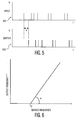
- Fig. 5 illustrates a relay function suitable for use by processor 310.
- This figure shows a sensed neural signal 501 and an output stimulus signal 502, having a fixed delay with respect to the sensed neural signal.
- a stimulus pulse is generated after a given delay by the stimulator.
- Both signals are illustrated in terms of voltage as a function of time.
- a typical delay value d is 0.1 - 10 ms.
- the particular sequence of impulses is only an exemplary illustration.Other sequences may be used. Modulatory inputs may be used to increase/decrease this delay d.
- Fig. 6 illustrates a frequency transformation function alternatively suitable for use by processor 310.
- the frequency of a sensed signal (action-potential-train, or field potential) shown on the horizontal axis is coupled to the frequency of the output pulse-train, shown on the vertical axis.
- F0 indicates the intercept with the horizontal axis and "a” indicates an angle with which the function intersects the horizontal axis.
- the "F0" and “a” can be modulated by other inputs, e.g. feedback signals, or other signals.
- the function is shown as linear here, but may take on other forms
- Figure 7 illustrates a pulse train producible by stimulus emitter 311.
- the figure shows pulse voltage or current as a function of time.
- the figure shows a pulse of amplitude A, delay d', and width w.
- Typical ranges are amplitude of 0.1 to 4 volts (or 0.1 - 4 mA, depending on electrode impedance) and pulse width of 10 - 1000 ⁇ s.
- dyskinesia especially that associated with Parkinson's disease will respond to a prosthetic of the sort illustrated in Fig. 3 , because dyskinesia is believed to be caused by excess stimulation, uncompensated by feedback, and not tuned to the exact intention by feed-forward.
- Fig. 8 shows an alternate embodiment to Figure 3 .
- the last two digits in the reference numerals of the boxes and ellipses indicate correspondence with those boxes and ellipses having the same last two digits in Fig. 3 .
- the affected region 807 has bidirectional signal flow 813, 823, 824, 825 with the afferent and efferent regions.
- Outputs 823 and 825 from 807 are again illustrated with dotted lines indicating that they are expected to be compromised when region 807 becomes compromised.
- Fig. 8 includes two additional feedback pathways 820 and 821, not illustrated in Fig. 3 .
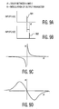
- Figs 9a-d illustrate an embodiment of the modulation of neurostimulator output based on sensed signals.
- Figs 9A and 9B show two sensed signals, input 1 and input 2.
- Each sensed signal includes an input pulse 901 and 902, respectively.
- an output characteristic is modulated according to sensed signals at two sensors.
- the modulation amplitude per time step is indicated by ⁇ and in this example it is related to the time delay dt between detected signals on sensors 1 and 2.
- the output being modulated can be e.g. a continuous pulse train as indicated in Fig 7 of which the modulation is applied to one or more parameters (e.g. pulse amplitude, pulse width, or pulse frequency).
- ⁇ in this example depend on dt as indicated in the two sketches Fig 9C and Fig. 9D .
- the modulation is strongly positive and drops for more positive dt values; for small negative dt the modulation is strongly negative, becoming less negative for more negative dt values.
- the second example shows an alternative dependence of modulation on dt; it is close to zero for small dt values and has strongly positive (negative) value around a specific negative (positive) dt value and drops to zero again for large negative and positive dt values.
- the modulation the biomimetic prosthetic is trained to use will depend on what neurological function is to be replaced.
- processors 310 and 810 In general, the function performed by processors 310 and 810 will usually be learned by reference to experimental data and therefore not necessarily predictable in advance.
Landscapes
- Health & Medical Sciences (AREA)
- Life Sciences & Earth Sciences (AREA)
- Neurology (AREA)
- Veterinary Medicine (AREA)
- Engineering & Computer Science (AREA)
- Public Health (AREA)
- General Health & Medical Sciences (AREA)
- Animal Behavior & Ethology (AREA)
- Radiology & Medical Imaging (AREA)
- Nuclear Medicine, Radiotherapy & Molecular Imaging (AREA)
- Biomedical Technology (AREA)
- Neurosurgery (AREA)
- Heart & Thoracic Surgery (AREA)
- Psychology (AREA)
- Cardiology (AREA)
- Biophysics (AREA)
- Hospice & Palliative Care (AREA)
- Child & Adolescent Psychology (AREA)
- Psychiatry (AREA)
- Social Psychology (AREA)
- Developmental Disabilities (AREA)
- Physiology (AREA)
- Electrotherapy Devices (AREA)
- Magnetic Treatment Devices (AREA)
- Measurement Of The Respiration, Hearing Ability, Form, And Blood Characteristics Of Living Organisms (AREA)
Claims (10)
- Dispositif neuromimétique comprenant :au moins une première et une seconde entrée (317, 318) adaptées à recevoir des signaux neuraux, la première entrée (317) étant disposée pour recevoir des signaux afférents à une région suspecte (307) et la seconde entrée (318) étant adaptée à recevoir des signaux depuis une région neurale efférente (308) autre que et efférente à la région suspecte (307) ;au moins une sortie (316) adaptée à émettre des signaux neuraux compatibles vers la région neurale efférente (308), les signaux neuraux compatibles simulant une réponse aux signaux afférents à la région suspecte (307) ; etau moins un appareil de traitement de signaux comprenant un trajet vers l'avant (309, 310, 311) agencé entre la première entrée et la sortie (316) et un trajet de modulation (312) agencé pour recevoir des signaux provenant de la seconde entrée (308) et fournir un signal de modulation au trajet vers l'avant.
- Dispositif selon la revendication 1, dans lequel le trajet vers l'avant comprend au moins un processeur pour exécuter des opérations, les opérations comprenant :la surveillance (401) de signaux reçus depuis la première et la seconde entrée pendant une première période temporelle ;l'entraînement (407) du processeur pendant la première période temporelle pour produire des fonctions de traitement et produire des signaux reçus à la seconde entrée en réponse à des signaux reçus à la première entrée ;la détection (402) que la région suspecte est devenue en dysfonctionnement après la première période temporelle ;l'exécution (403) des fonctions de traitement apprises pendant une seconde période temporelle ;la surveillance (404) de signaux reçus depuis la première et la seconde entrée pendant la seconde période temporelle ; etla modification (406) des fonctions de traitement pendant la seconde période temporelle, en réponse à une détermination (405) que les signaux reçus à la seconde entrée ne s'accordent pas avec des signaux appris pendant l'opération d'entraînement.
- Dispositif selon la revendication 2, comprenant en outre au moins une troisième entrée (330) pour recevoir des signaux générés de façon externe (315) à un corps d'un patient, et dans lequel la détection réagit aux signaux reçus à la troisième entrée.
- Dispositif selon la revendication 1, dans lequel le trajet vers l'avant comprend une unité d'émission de stimuli (311) couplée à l'entrée.
- Dispositif selon la revendication 1, dans lequel la seconde entrée est agencée pour recevoir des signaux efférents à la sortie, et dans lequel la modulation comprend une rétroaction en réponse à ces signaux efférents.
- Dispositif selon la revendication 1, comprenant en outre au moins une troisième entrée (330) pour recevoir des signaux générés de façon externe (315) à un corps d'un patient.
- Dispositif selon la revendication 1, dans lequel le trajet vers l'avant comprend :un premier capteur (309) agencé pour recevoir des premiers signaux délivrés depuis une première région neurale afférente (306) dont on s'attend qu'elle reste saine ;un processeur (310) adapté à apprendre et à émuler des fonctions de la région suspecte (307), qui est une seconde région neurale ; etun émetteur de stimuli (311) agencé pour fournir des signaux vers une troisième région neurale efférente (308) dont on s'attend qu'elle reste saine.
- Dispositif selon la revendication 7, dans lequel le trajet de modulation comprend un second capteur (312) agencé pour recevoir des signaux depuis une quatrième région efférente à une sortie de l'émetteur de stimuli (311) et fournir un signal de modulation au processeur (310).
- Dispositif selon la revendication 7, dans lequel :la région suspecte (807) communique de façon bidirectionnelle (813, 823, 824, 825) avec la première et la troisième région neurale (806, 808), le premier capteur (809) est en outre agencé pour recevoir des seconds signaux efférents à la région suspecte, mais afférents à une sortie (816) de l'unité émettrice de stimuli (811), etle dispositif comprend en outre un trajet de rétroaction (821) depuis l'unité émettrice de stimuli (811) vers une zone afférente à la première entrée vers le premier capteur.
- Dispositif selon la revendication 1, dans lequel la région suspecte (807) est attendue pour communiquer de façon bidirectionnelle (813, 823, 824, 825) avec les tissus adjacents, et le dispositif comprend en outre :un premier coupleur (820) vers le premier capteur (809) depuis une région située entre la région suspecte et une sortie de l'unité émettrice de stimuli ; etun second coupleur (821) vers la première région neurale (806) depuis l'unité émettrice de stimuli.
Applications Claiming Priority (2)
| Application Number | Priority Date | Filing Date | Title |
|---|---|---|---|
| US87122706P | 2006-12-21 | 2006-12-21 | |
| PCT/IB2007/055215 WO2008075294A1 (fr) | 2006-12-21 | 2007-12-18 | Dispositif de neurostimulation biomimétique |
Publications (2)
| Publication Number | Publication Date |
|---|---|
| EP2097134A1 EP2097134A1 (fr) | 2009-09-09 |
| EP2097134B1 true EP2097134B1 (fr) | 2014-02-12 |
Family
ID=39323862
Family Applications (1)
| Application Number | Title | Priority Date | Filing Date |
|---|---|---|---|
| EP07859442.1A Not-in-force EP2097134B1 (fr) | 2006-12-21 | 2007-12-18 | Dispositif de neurostimulation biomimétique |
Country Status (6)
| Country | Link |
|---|---|
| US (2) | US8923977B2 (fr) |
| EP (1) | EP2097134B1 (fr) |
| JP (1) | JP2010512926A (fr) |
| CN (1) | CN101636196A (fr) |
| RU (1) | RU2461397C2 (fr) |
| WO (1) | WO2008075294A1 (fr) |
Families Citing this family (63)
| Publication number | Priority date | Publication date | Assignee | Title |
|---|---|---|---|---|
| WO2008075294A1 (fr) * | 2006-12-21 | 2008-06-26 | Koninklijke Philips Electronics, N.V. | Dispositif de neurostimulation biomimétique |
| EP2644227B1 (fr) | 2008-07-30 | 2016-12-28 | Ecole Polytechnique Fédérale de Lausanne | Appareil de stimulation optimisée d'une cible neurologique |
| CA2743575C (fr) | 2008-11-12 | 2017-01-31 | Ecole Polytechnique Federale De Lausanne | Dispositif de neurostimulation microfabrique |
| RU2401137C1 (ru) * | 2009-02-24 | 2010-10-10 | Дмитрий Васильевич Белик | Система стимуляции функционирования органов |
| CA2782710C (fr) | 2009-12-01 | 2019-01-22 | Ecole Polytechnique Federale De Lausanne | Dispositif de neurostimulation microfabrique et ses procedes de fabrication et d'utilisation |
| EP2552536B1 (fr) | 2010-04-01 | 2016-06-08 | Ecole Polytechnique Fédérale de Lausanne (EPFL) | Dispositif d'interaction avec un tissu neurologique |
| CA2823592C (fr) | 2011-01-03 | 2021-11-23 | The Regents Of The University Of California | Stimulation epidurale a haute densite pour faciliter la locomotion, la posture, le mouvement volontaire et le retablissement de la fonction d'autonomie, sexuelle, vasomotrice et c ognitive apres lesion neurologique |
| KR20140013043A (ko) | 2011-03-24 | 2014-02-04 | 캘리포니아 인스티튜트 오브 테크놀로지 | 신경자극기 |
| ES2584388T3 (es) | 2011-07-27 | 2016-09-27 | Université Pierre Et Marie Curie (Paris 6) | Dispositivo de tratamiento de la capacidad sensorial de una persona |
| JP2014533183A (ja) | 2011-11-11 | 2014-12-11 | ニューロイネイブリング テクノロジーズ インコーポレイテッド | 運動神経、感覚、自律、性的、血管運動および認知機能の回復を可能にするための非侵襲性神経調節装置 |
| US10092750B2 (en) | 2011-11-11 | 2018-10-09 | Neuroenabling Technologies, Inc. | Transcutaneous neuromodulation system and methods of using same |
| US12453853B2 (en) | 2013-01-21 | 2025-10-28 | Cala Health, Inc. | Multi-modal stimulation for treating tremor |
| EP3498332B1 (fr) | 2013-01-21 | 2021-07-14 | Cala Health, Inc. | Dispositifs de contrôle de tremblements |
| AU2014228794B2 (en) | 2013-03-15 | 2019-04-18 | The Regents Of The University Of California | Multi-site transcutaneous electrical stimulation of the spinal cord for facilitation of locomotion |
| DE102013105010B4 (de) * | 2013-05-15 | 2020-09-10 | Bildungszentrum für informationsverarbeitende Berufe gGmbH | Messsystem, Anordnung und Verfahren zur Auswertung von Nervensignalen |
| US10137299B2 (en) | 2013-09-27 | 2018-11-27 | The Regents Of The University Of California | Engaging the cervical spinal cord circuitry to re-enable volitional control of hand function in tetraplegic subjects |
| US20150217120A1 (en) | 2014-01-13 | 2015-08-06 | Mandheerej Nandra | Neuromodulation systems and methods of using same |
| WO2015196164A2 (fr) | 2014-06-21 | 2015-12-23 | Accelemed, Llc | Procédé et appareil de traitements de neuromodulation de la douleur et d'autres états |
| WO2015173787A1 (fr) | 2014-05-16 | 2015-11-19 | Aleva Neurotherapeutics Sa | Dispositif pour l'interaction avec un tissu neurologique et procédés de fabrication et d'utilisation associés |
| US11311718B2 (en) | 2014-05-16 | 2022-04-26 | Aleva Neurotherapeutics Sa | Device for interacting with neurological tissue and methods of making and using the same |
| AU2015271774B2 (en) | 2014-06-02 | 2020-04-16 | Cala Health, Inc. | Systems and methods for peripheral nerve stimulation to treat tremor |
| US9474894B2 (en) | 2014-08-27 | 2016-10-25 | Aleva Neurotherapeutics | Deep brain stimulation lead |
| US9403011B2 (en) | 2014-08-27 | 2016-08-02 | Aleva Neurotherapeutics | Leadless neurostimulator |
| HK1251190A1 (zh) | 2014-12-19 | 2019-01-25 | 皮埃尔与玛丽‧居里-巴黎第六大学 | 用於脑治疗的可植入的超声发生治疗装置、包括此装置的设备以及实施此装置的方法 |
| CN119565022A (zh) | 2015-06-10 | 2025-03-07 | 卡拉健康公司 | 用于外周神经刺激以利用可拆卸治疗和监测单元治疗震颤的系统和方法 |
| WO2017023864A1 (fr) | 2015-07-31 | 2017-02-09 | Cala Health, Inc. | Systèmes, dispositifs et procédé permettant le traitement de l'arthrose |
| WO2017044904A1 (fr) | 2015-09-11 | 2017-03-16 | Nalu Medical, Inc. | Appareil de stimulation périphérique ou spinale |
| EP3352843B1 (fr) | 2015-09-23 | 2021-06-23 | Cala Health, Inc. | Dispositif pour la stimulation des nerfs périphériques dans le doigt pour traiter des tremblements dans la main |
| US11097122B2 (en) | 2015-11-04 | 2021-08-24 | The Regents Of The University Of California | Magnetic stimulation of the spinal cord to restore control of bladder and/or bowel |
| WO2017132067A2 (fr) | 2016-01-21 | 2017-08-03 | Cala Health, Inc. | Systèmes, procédés et dispositifs de neuromodulation périphérique pour le traitement de maladies associées à une hyperactivitévésicale |
| WO2017134587A1 (fr) | 2016-02-02 | 2017-08-10 | Aleva Neurotherapeutics, Sa | Traitement de maladies auto-immunes par stimulation cérébrale profonde |
| AU2017221321B2 (en) | 2016-02-19 | 2021-04-15 | Nalu Medical, Inc. | Apparatus with enhanced stimulation waveforms |
| CN109414243B (zh) | 2016-03-11 | 2022-03-29 | 索邦大学 | 用于脊髓和脊神经治疗的外部超声波生成治疗装置、包括该装置的设备和实施该装置的方法 |
| EP3426347B1 (fr) | 2016-03-11 | 2024-05-15 | Sorbonne Universite | Dispositif de traitement implantable générant des ultrasons pour le traitement de la moelle épinière et appareil comprenant un tel dispositif |
| WO2017165410A1 (fr) | 2016-03-21 | 2017-09-28 | Nalu Medical, Inc. | Dispositifs et procédés de positionnement de dispositifs externes par rapport à des dispositifs implantés |
| EP3484577B1 (fr) | 2016-07-18 | 2025-06-18 | Nalu Medical, Inc. | Systèmes de traitement de troubles pelviens et d'affections douloureuses |
| CN109803717B (zh) | 2016-08-25 | 2024-01-09 | 卡拉健康公司 | 通过周围神经刺激治疗心脏机能障碍的系统和方法 |
| WO2018101986A1 (fr) | 2016-12-01 | 2018-06-07 | Thimble Bioelectronics, Inc. d/b/a Enso | Dispositif de neuromodulation et son procédé d'utilisation |
| WO2018126062A1 (fr) | 2016-12-30 | 2018-07-05 | Nalu Medical, Inc. | Appareil de stimulation |
| US11235154B2 (en) | 2017-02-17 | 2022-02-01 | The University Of British Columbia | Apparatus and methods for maintaining physiological functions |
| EP3585475B1 (fr) | 2017-02-24 | 2024-04-03 | Nalu Medical, Inc. | Appareil avec stimulateurs implantés séquentiellement |
| EP3606604A4 (fr) | 2017-04-03 | 2020-12-16 | Cala Health, Inc. | Systèmes, procédés et dispositifs de neuromodulation périphérique pour le traitement de maladies associées à une hyperactivitévésicale |
| WO2018208992A1 (fr) | 2017-05-09 | 2018-11-15 | Nalu Medical, Inc. | Appareil de stimulation |
| WO2018217791A1 (fr) | 2017-05-23 | 2018-11-29 | The Regents Of The University Of California | Accès aux réseaux spinaux dans le traitement de la dysfonction sexuelle |
| DE20168827T1 (de) | 2017-06-30 | 2021-01-21 | Gtx Medical B.V. | System zur neuromodulierung |
| KR102495358B1 (ko) | 2017-09-25 | 2023-02-02 | 삼성전자주식회사 | 신경모방 자극 장치 및 그 방법 |
| ES3058711T3 (en) | 2017-12-05 | 2026-03-12 | Ecole Polytechnique Fed Lausanne Epfl | A system for planning and/or providing neuromodulation |
| US12357828B2 (en) | 2017-12-05 | 2025-07-15 | Ecole Polytechnique Federale De Lausanne (Epfl) | System for planning and/or providing neuromodulation |
| US11857778B2 (en) | 2018-01-17 | 2024-01-02 | Cala Health, Inc. | Systems and methods for treating inflammatory bowel disease through peripheral nerve stimulation |
| US10702692B2 (en) | 2018-03-02 | 2020-07-07 | Aleva Neurotherapeutics | Neurostimulation device |
| JP2021534877A (ja) | 2018-08-23 | 2021-12-16 | ザ リージェンツ オブ ザ ユニバーシティ オブ カリフォルニアThe Regents Of The University Of California | 神経根麻痺、馬尾症候群、及び上肢機能の回復のための非侵襲性脊髄刺激 |
| ES2911465T3 (es) | 2018-11-13 | 2022-05-19 | Onward Medical N V | Sistema de control para la reconstrucción y/o restauración del movimiento de un paciente |
| DE18205817T1 (de) | 2018-11-13 | 2020-12-24 | Gtx Medical B.V. | Sensor in bekleidung von gliedmassen oder schuhwerk |
| EP3695878B1 (fr) | 2019-02-12 | 2023-04-19 | ONWARD Medical N.V. | Système de neuromodulation |
| EP3744385A1 (fr) | 2019-05-20 | 2020-12-02 | Biopro Scientific Co., Ltd. | Système de traitement de troubles neuronaux |
| EP3750592B1 (fr) | 2019-05-20 | 2024-07-03 | Biopro Scientific Co., Ltd. | Système de traitement des troubles du mouvement |
| EP3993866A4 (fr) | 2019-07-02 | 2023-07-12 | Nalu Medical, Inc. | Appareil de stimulation |
| US12251560B1 (en) | 2019-08-13 | 2025-03-18 | Cala Health, Inc. | Connection quality determination for wearable neurostimulation systems |
| US11890468B1 (en) | 2019-10-03 | 2024-02-06 | Cala Health, Inc. | Neurostimulation systems with event pattern detection and classification |
| EP3827875B1 (fr) | 2019-11-27 | 2023-07-05 | ONWARD Medical N.V. | Systeme de neuromodulation |
| DE19211698T1 (de) | 2019-11-27 | 2021-09-02 | Onward Medical B.V. | Neuromodulation system |
| US11745902B1 (en) * | 2019-12-11 | 2023-09-05 | Government Of The United States As Represented By The Secretary Of The Air Force | Systems, methods and apparatus for multifunctional central pattern generator |
| WO2021151050A1 (fr) * | 2020-01-25 | 2021-07-29 | The Regents Of The University Of California | Système stimulateur biomimétique pour implant neuronal |
Family Cites Families (8)
| Publication number | Priority date | Publication date | Assignee | Title |
|---|---|---|---|---|
| US5702429A (en) * | 1996-04-04 | 1997-12-30 | Medtronic, Inc. | Neural stimulation techniques with feedback |
| US5716377A (en) * | 1996-04-25 | 1998-02-10 | Medtronic, Inc. | Method of treating movement disorders by brain stimulation |
| RU2081637C1 (ru) | 1996-06-25 | 1997-06-20 | Хворостов Сергей Александрович | Способ воздействия на психиатрические и психоневрологические способности организма |
| EP1559369B1 (fr) | 1999-06-11 | 2012-03-28 | Cornell Research Foundation, Inc. | Mécanisme de rétroaction pour la stimulation cérébrale profonde |
| RU2214842C1 (ru) | 2002-10-29 | 2003-10-27 | Лебедев Валерий Павлович | Способ лечения нейросенсорной тугоухости и устройство для его осуществления |
| US20050113744A1 (en) * | 2003-11-21 | 2005-05-26 | Cyberkinetics, Inc. | Agent delivery systems and related methods under control of biological electrical signals |
| DE10355652A1 (de) | 2003-11-28 | 2005-06-30 | Forschungszentrum Jülich GmbH | Verfahren und Vorrichtung zur Desynchronisation neuronaler Hirnaktivität |
| WO2008075294A1 (fr) * | 2006-12-21 | 2008-06-26 | Koninklijke Philips Electronics, N.V. | Dispositif de neurostimulation biomimétique |
-
2007
- 2007-12-18 WO PCT/IB2007/055215 patent/WO2008075294A1/fr not_active Ceased
- 2007-12-18 CN CN200780047593.5A patent/CN101636196A/zh active Pending
- 2007-12-18 JP JP2009542363A patent/JP2010512926A/ja active Pending
- 2007-12-18 RU RU2009128056/14A patent/RU2461397C2/ru not_active IP Right Cessation
- 2007-12-18 US US12/519,813 patent/US8923977B2/en active Active
- 2007-12-18 EP EP07859442.1A patent/EP2097134B1/fr not_active Not-in-force
-
2014
- 2014-11-20 US US14/548,776 patent/US9144681B2/en active Active
Also Published As
| Publication number | Publication date |
|---|---|
| US9144681B2 (en) | 2015-09-29 |
| CN101636196A (zh) | 2010-01-27 |
| WO2008075294A1 (fr) | 2008-06-26 |
| US20150080987A1 (en) | 2015-03-19 |
| RU2461397C2 (ru) | 2012-09-20 |
| EP2097134A1 (fr) | 2009-09-09 |
| WO2008075294A9 (fr) | 2009-02-19 |
| US20100145414A1 (en) | 2010-06-10 |
| JP2010512926A (ja) | 2010-04-30 |
| RU2009128056A (ru) | 2011-01-27 |
| US8923977B2 (en) | 2014-12-30 |
Similar Documents
| Publication | Publication Date | Title |
|---|---|---|
| EP2097134B1 (fr) | Dispositif de neurostimulation biomimétique | |
| US11298541B2 (en) | Method and apparatus for improving cognitive performance | |
| US11923093B2 (en) | Systems and methods for VOA model generation and use | |
| US5800474A (en) | Method of controlling epilepsy by brain stimulation | |
| CN101115524B (zh) | 使神经元脑活动去同步化的方法和设备 | |
| US8000794B2 (en) | Method and apparatus for affecting neurologic function and/or treating Neurologic dysfunction through timed neural stimulation | |
| EP3824372B1 (fr) | Système de communication neuronal | |
| Camara et al. | Resting tremor classification and detection in Parkinson's disease patients | |
| Kuo et al. | Approaches to closed-loop deep brain stimulation for movement disorders | |
| US5752979A (en) | Method of controlling epilepsy by brain stimulation | |
| EP1102607B1 (fr) | Dispositif de stimulation electrique avec retroaction pour ameliorer le traitement d'une maladie neurologique | |
| US20050222626A1 (en) | Cloosed-loop feedback-driven neuromodulation | |
| US20090018609A1 (en) | Closed-Loop Feedback-Driven Neuromodulation | |
| KR20190034867A (ko) | 신경모방 자극 장치 및 그 방법 | |
| DE102019214752B4 (de) | Neuronales signalsystem, verfahren und computerprogramm zumsignalisieren eines gerätezustands | |
| WO2020095111A1 (fr) | Méthodes et systèmes pour une détection d'équilibre entre des entrées et des voies d'activité neuronale et une neuromodulation | |
| Stanslaski et al. | Fully closed loop test environment for adaptive implantable neural stimulators using computational models | |
| Pan et al. | Prediction of Parkinson’s disease tremor onset using artificial neural networks | |
| Koppert et al. | Reactive control of epileptiform discharges in realistic computational neuronal models with bistability | |
| Beudel et al. | Future perspectives: adaptive deep brain stimulation | |
| Baker et al. | Regulation of arousal and performance of a healthy non-human primate using closed-loop central thalamic deep brain stimulation | |
| Montgomery Jr | Deep brain stimulation and speech: a new model of speech function and dysfunction in Parkinson's disease | |
| Kuzmina et al. | Neurophysiologically Realistic Environment for Comparing Adaptive Deep Brain Stimulation Algorithms in Parkinson's Disease | |
| Caldwell et al. | Motor BMIs have entered the clinical realm | |
| Lombardi | Valutazione comparativa degli algoritmi che costituiscono lo stato dell’arte nel rilevamento di up state in registrazioni intracorticali in vivo. |
Legal Events
| Date | Code | Title | Description |
|---|---|---|---|
| PUAI | Public reference made under article 153(3) epc to a published international application that has entered the european phase |
Free format text: ORIGINAL CODE: 0009012 |
|
| 17P | Request for examination filed |
Effective date: 20090721 |
|
| AK | Designated contracting states |
Kind code of ref document: A1 Designated state(s): AT BE BG CH CY CZ DE DK EE ES FI FR GB GR HU IE IS IT LI LT LU LV MC MT NL PL PT RO SE SI SK TR |
|
| DAX | Request for extension of the european patent (deleted) | ||
| 17Q | First examination report despatched |
Effective date: 20110210 |
|
| RAP1 | Party data changed (applicant data changed or rights of an application transferred) |
Owner name: SAPIENS STEERING BRAIN STIMULATION B.V. |
|
| RAP1 | Party data changed (applicant data changed or rights of an application transferred) |
Owner name: SAPIENS STEERING BRAIN STIMULATION B.V. |
|
| GRAP | Despatch of communication of intention to grant a patent |
Free format text: ORIGINAL CODE: EPIDOSNIGR1 |
|
| RIC1 | Information provided on ipc code assigned before grant |
Ipc: A61N 2/00 20060101ALN20130703BHEP Ipc: A61N 1/36 20060101AFI20130703BHEP |
|
| INTG | Intention to grant announced |
Effective date: 20130725 |
|
| GRAS | Grant fee paid |
Free format text: ORIGINAL CODE: EPIDOSNIGR3 |
|
| GRAA | (expected) grant |
Free format text: ORIGINAL CODE: 0009210 |
|
| AK | Designated contracting states |
Kind code of ref document: B1 Designated state(s): AT BE BG CH CY CZ DE DK EE ES FI FR GB GR HU IE IS IT LI LT LU LV MC MT NL PL PT RO SE SI SK TR |
|
| REG | Reference to a national code |
Ref country code: GB Ref legal event code: FG4D |
|
| REG | Reference to a national code |
Ref country code: CH Ref legal event code: EP |
|
| REG | Reference to a national code |
Ref country code: AT Ref legal event code: REF Ref document number: 651865 Country of ref document: AT Kind code of ref document: T Effective date: 20140215 |
|
| REG | Reference to a national code |
Ref country code: IE Ref legal event code: FG4D |
|
| REG | Reference to a national code |
Ref country code: DE Ref legal event code: R096 Ref document number: 602007035099 Country of ref document: DE Effective date: 20140327 |
|
| REG | Reference to a national code |
Ref country code: NL Ref legal event code: VDEP Effective date: 20140212 |
|
| REG | Reference to a national code |
Ref country code: AT Ref legal event code: MK05 Ref document number: 651865 Country of ref document: AT Kind code of ref document: T Effective date: 20140212 |
|
| REG | Reference to a national code |
Ref country code: LT Ref legal event code: MG4D |
|
| PG25 | Lapsed in a contracting state [announced via postgrant information from national office to epo] |
Ref country code: IS Free format text: LAPSE BECAUSE OF FAILURE TO SUBMIT A TRANSLATION OF THE DESCRIPTION OR TO PAY THE FEE WITHIN THE PRESCRIBED TIME-LIMIT Effective date: 20140612 Ref country code: LT Free format text: LAPSE BECAUSE OF FAILURE TO SUBMIT A TRANSLATION OF THE DESCRIPTION OR TO PAY THE FEE WITHIN THE PRESCRIBED TIME-LIMIT Effective date: 20140212 |
|
| PG25 | Lapsed in a contracting state [announced via postgrant information from national office to epo] |
Ref country code: NL Free format text: LAPSE BECAUSE OF FAILURE TO SUBMIT A TRANSLATION OF THE DESCRIPTION OR TO PAY THE FEE WITHIN THE PRESCRIBED TIME-LIMIT Effective date: 20140212 Ref country code: FI Free format text: LAPSE BECAUSE OF FAILURE TO SUBMIT A TRANSLATION OF THE DESCRIPTION OR TO PAY THE FEE WITHIN THE PRESCRIBED TIME-LIMIT Effective date: 20140212 Ref country code: SE Free format text: LAPSE BECAUSE OF FAILURE TO SUBMIT A TRANSLATION OF THE DESCRIPTION OR TO PAY THE FEE WITHIN THE PRESCRIBED TIME-LIMIT Effective date: 20140212 Ref country code: ES Free format text: LAPSE BECAUSE OF FAILURE TO SUBMIT A TRANSLATION OF THE DESCRIPTION OR TO PAY THE FEE WITHIN THE PRESCRIBED TIME-LIMIT Effective date: 20140212 Ref country code: CY Free format text: LAPSE BECAUSE OF FAILURE TO SUBMIT A TRANSLATION OF THE DESCRIPTION OR TO PAY THE FEE WITHIN THE PRESCRIBED TIME-LIMIT Effective date: 20140212 Ref country code: PT Free format text: LAPSE BECAUSE OF FAILURE TO SUBMIT A TRANSLATION OF THE DESCRIPTION OR TO PAY THE FEE WITHIN THE PRESCRIBED TIME-LIMIT Effective date: 20140612 Ref country code: AT Free format text: LAPSE BECAUSE OF FAILURE TO SUBMIT A TRANSLATION OF THE DESCRIPTION OR TO PAY THE FEE WITHIN THE PRESCRIBED TIME-LIMIT Effective date: 20140212 |
|
| PG25 | Lapsed in a contracting state [announced via postgrant information from national office to epo] |
Ref country code: BE Free format text: LAPSE BECAUSE OF FAILURE TO SUBMIT A TRANSLATION OF THE DESCRIPTION OR TO PAY THE FEE WITHIN THE PRESCRIBED TIME-LIMIT Effective date: 20140212 Ref country code: LV Free format text: LAPSE BECAUSE OF FAILURE TO SUBMIT A TRANSLATION OF THE DESCRIPTION OR TO PAY THE FEE WITHIN THE PRESCRIBED TIME-LIMIT Effective date: 20140212 |
|
| PG25 | Lapsed in a contracting state [announced via postgrant information from national office to epo] |
Ref country code: EE Free format text: LAPSE BECAUSE OF FAILURE TO SUBMIT A TRANSLATION OF THE DESCRIPTION OR TO PAY THE FEE WITHIN THE PRESCRIBED TIME-LIMIT Effective date: 20140212 Ref country code: DK Free format text: LAPSE BECAUSE OF FAILURE TO SUBMIT A TRANSLATION OF THE DESCRIPTION OR TO PAY THE FEE WITHIN THE PRESCRIBED TIME-LIMIT Effective date: 20140212 Ref country code: RO Free format text: LAPSE BECAUSE OF FAILURE TO SUBMIT A TRANSLATION OF THE DESCRIPTION OR TO PAY THE FEE WITHIN THE PRESCRIBED TIME-LIMIT Effective date: 20140212 Ref country code: CZ Free format text: LAPSE BECAUSE OF FAILURE TO SUBMIT A TRANSLATION OF THE DESCRIPTION OR TO PAY THE FEE WITHIN THE PRESCRIBED TIME-LIMIT Effective date: 20140212 |
|
| REG | Reference to a national code |
Ref country code: DE Ref legal event code: R097 Ref document number: 602007035099 Country of ref document: DE |
|
| PG25 | Lapsed in a contracting state [announced via postgrant information from national office to epo] |
Ref country code: SK Free format text: LAPSE BECAUSE OF FAILURE TO SUBMIT A TRANSLATION OF THE DESCRIPTION OR TO PAY THE FEE WITHIN THE PRESCRIBED TIME-LIMIT Effective date: 20140212 Ref country code: PL Free format text: LAPSE BECAUSE OF FAILURE TO SUBMIT A TRANSLATION OF THE DESCRIPTION OR TO PAY THE FEE WITHIN THE PRESCRIBED TIME-LIMIT Effective date: 20140212 |
|
| PLBE | No opposition filed within time limit |
Free format text: ORIGINAL CODE: 0009261 |
|
| STAA | Information on the status of an ep patent application or granted ep patent |
Free format text: STATUS: NO OPPOSITION FILED WITHIN TIME LIMIT |
|
| 26N | No opposition filed |
Effective date: 20141113 |
|
| REG | Reference to a national code |
Ref country code: DE Ref legal event code: R082 Ref document number: 602007035099 Country of ref document: DE Representative=s name: DTS PATENT- UND RECHTSANWAELTE SCHNEKENBUEHL U, DE |
|
| REG | Reference to a national code |
Ref country code: DE Ref legal event code: R097 Ref document number: 602007035099 Country of ref document: DE Effective date: 20141113 |
|
| PG25 | Lapsed in a contracting state [announced via postgrant information from national office to epo] |
Ref country code: IT Free format text: LAPSE BECAUSE OF FAILURE TO SUBMIT A TRANSLATION OF THE DESCRIPTION OR TO PAY THE FEE WITHIN THE PRESCRIBED TIME-LIMIT Effective date: 20140212 |
|
| PG25 | Lapsed in a contracting state [announced via postgrant information from national office to epo] |
Ref country code: SI Free format text: LAPSE BECAUSE OF FAILURE TO SUBMIT A TRANSLATION OF THE DESCRIPTION OR TO PAY THE FEE WITHIN THE PRESCRIBED TIME-LIMIT Effective date: 20140212 |
|
| PG25 | Lapsed in a contracting state [announced via postgrant information from national office to epo] |
Ref country code: LU Free format text: LAPSE BECAUSE OF FAILURE TO SUBMIT A TRANSLATION OF THE DESCRIPTION OR TO PAY THE FEE WITHIN THE PRESCRIBED TIME-LIMIT Effective date: 20141218 |
|
| REG | Reference to a national code |
Ref country code: CH Ref legal event code: PL |
|
| REG | Reference to a national code |
Ref country code: IE Ref legal event code: MM4A |
|
| PG25 | Lapsed in a contracting state [announced via postgrant information from national office to epo] |
Ref country code: CH Free format text: LAPSE BECAUSE OF NON-PAYMENT OF DUE FEES Effective date: 20141231 Ref country code: IE Free format text: LAPSE BECAUSE OF NON-PAYMENT OF DUE FEES Effective date: 20141218 Ref country code: LI Free format text: LAPSE BECAUSE OF NON-PAYMENT OF DUE FEES Effective date: 20141231 |
|
| REG | Reference to a national code |
Ref country code: FR Ref legal event code: PLFP Year of fee payment: 9 |
|
| PGFP | Annual fee paid to national office [announced via postgrant information from national office to epo] |
Ref country code: GB Payment date: 20151229 Year of fee payment: 9 |
|
| PGFP | Annual fee paid to national office [announced via postgrant information from national office to epo] |
Ref country code: FR Payment date: 20151217 Year of fee payment: 9 |
|
| PG25 | Lapsed in a contracting state [announced via postgrant information from national office to epo] |
Ref country code: BG Free format text: LAPSE BECAUSE OF FAILURE TO SUBMIT A TRANSLATION OF THE DESCRIPTION OR TO PAY THE FEE WITHIN THE PRESCRIBED TIME-LIMIT Effective date: 20140212 Ref country code: MC Free format text: LAPSE BECAUSE OF FAILURE TO SUBMIT A TRANSLATION OF THE DESCRIPTION OR TO PAY THE FEE WITHIN THE PRESCRIBED TIME-LIMIT Effective date: 20140212 |
|
| PG25 | Lapsed in a contracting state [announced via postgrant information from national office to epo] |
Ref country code: GR Free format text: LAPSE BECAUSE OF FAILURE TO SUBMIT A TRANSLATION OF THE DESCRIPTION OR TO PAY THE FEE WITHIN THE PRESCRIBED TIME-LIMIT Effective date: 20140513 |
|
| PG25 | Lapsed in a contracting state [announced via postgrant information from national office to epo] |
Ref country code: TR Free format text: LAPSE BECAUSE OF FAILURE TO SUBMIT A TRANSLATION OF THE DESCRIPTION OR TO PAY THE FEE WITHIN THE PRESCRIBED TIME-LIMIT Effective date: 20140212 Ref country code: HU Free format text: LAPSE BECAUSE OF FAILURE TO SUBMIT A TRANSLATION OF THE DESCRIPTION OR TO PAY THE FEE WITHIN THE PRESCRIBED TIME-LIMIT; INVALID AB INITIO Effective date: 20071218 Ref country code: MT Free format text: LAPSE BECAUSE OF FAILURE TO SUBMIT A TRANSLATION OF THE DESCRIPTION OR TO PAY THE FEE WITHIN THE PRESCRIBED TIME-LIMIT Effective date: 20140212 |
|
| GBPC | Gb: european patent ceased through non-payment of renewal fee |
Effective date: 20161218 |
|
| REG | Reference to a national code |
Ref country code: FR Ref legal event code: ST Effective date: 20170831 |
|
| PG25 | Lapsed in a contracting state [announced via postgrant information from national office to epo] |
Ref country code: FR Free format text: LAPSE BECAUSE OF NON-PAYMENT OF DUE FEES Effective date: 20170102 |
|
| PG25 | Lapsed in a contracting state [announced via postgrant information from national office to epo] |
Ref country code: GB Free format text: LAPSE BECAUSE OF NON-PAYMENT OF DUE FEES Effective date: 20161218 |
|
| PGFP | Annual fee paid to national office [announced via postgrant information from national office to epo] |
Ref country code: DE Payment date: 20231121 Year of fee payment: 17 |
|
| REG | Reference to a national code |
Ref country code: DE Ref legal event code: R119 Ref document number: 602007035099 Country of ref document: DE |
|
| PG25 | Lapsed in a contracting state [announced via postgrant information from national office to epo] |
Ref country code: DE Free format text: LAPSE BECAUSE OF NON-PAYMENT OF DUE FEES Effective date: 20250701 |