EP2097227B1 - Boite a gant a enceinte etanche eclairee - Google Patents
Boite a gant a enceinte etanche eclairee Download PDFInfo
- Publication number
- EP2097227B1 EP2097227B1 EP07822757A EP07822757A EP2097227B1 EP 2097227 B1 EP2097227 B1 EP 2097227B1 EP 07822757 A EP07822757 A EP 07822757A EP 07822757 A EP07822757 A EP 07822757A EP 2097227 B1 EP2097227 B1 EP 2097227B1
- Authority
- EP
- European Patent Office
- Prior art keywords
- partition
- glove box
- light source
- polycarbonate
- biological protection
- Prior art date
- Legal status (The legal status is an assumption and is not a legal conclusion. Google has not performed a legal analysis and makes no representation as to the accuracy of the status listed.)
- Active
Links
- 238000005192 partition Methods 0.000 claims abstract description 68
- 229920000515 polycarbonate Polymers 0.000 claims description 25
- 239000004417 polycarbonate Substances 0.000 claims description 25
- 238000009792 diffusion process Methods 0.000 claims description 4
- 229910052782 aluminium Inorganic materials 0.000 claims description 3
- XAGFODPZIPBFFR-UHFFFAOYSA-N aluminium Chemical compound [Al] XAGFODPZIPBFFR-UHFFFAOYSA-N 0.000 claims description 3
- 239000005355 lead glass Substances 0.000 claims description 3
- 230000005855 radiation Effects 0.000 claims description 3
- 239000011521 glass Substances 0.000 claims description 2
- 229910052751 metal Inorganic materials 0.000 claims description 2
- 239000000113 methacrylic resin Substances 0.000 claims description 2
- 239000011358 absorbing material Substances 0.000 claims 2
- 239000004411 aluminium Substances 0.000 claims 1
- 238000005286 illumination Methods 0.000 description 3
- 238000012423 maintenance Methods 0.000 description 3
- 239000002699 waste material Substances 0.000 description 3
- 229920004142 LEXAN™ Polymers 0.000 description 2
- 239000004418 Lexan Substances 0.000 description 2
- 238000002513 implantation Methods 0.000 description 2
- 238000004519 manufacturing process Methods 0.000 description 2
- 229910000831 Steel Inorganic materials 0.000 description 1
- 239000002250 absorbent Substances 0.000 description 1
- 238000011109 contamination Methods 0.000 description 1
- 230000000694 effects Effects 0.000 description 1
- 230000004313 glare Effects 0.000 description 1
- 230000017525 heat dissipation Effects 0.000 description 1
- QSHDDOUJBYECFT-UHFFFAOYSA-N mercury Chemical compound [Hg] QSHDDOUJBYECFT-UHFFFAOYSA-N 0.000 description 1
- 239000002184 metal Substances 0.000 description 1
- 238000012986 modification Methods 0.000 description 1
- 230000004048 modification Effects 0.000 description 1
- 230000008447 perception Effects 0.000 description 1
- 238000005498 polishing Methods 0.000 description 1
- 239000010959 steel Substances 0.000 description 1
- 239000000126 substance Substances 0.000 description 1
- 238000012795 verification Methods 0.000 description 1
Images
Classifications
-
- G—PHYSICS
- G21—NUCLEAR PHYSICS; NUCLEAR ENGINEERING
- G21F—PROTECTION AGAINST X-RADIATION, GAMMA RADIATION, CORPUSCULAR RADIATION OR PARTICLE BOMBARDMENT; TREATING RADIOACTIVELY CONTAMINATED MATERIAL; DECONTAMINATION ARRANGEMENTS THEREFOR
- G21F7/00—Shielded cells or rooms
- G21F7/04—Shielded glove-boxes
- G21F7/043—Lighting
-
- B—PERFORMING OPERATIONS; TRANSPORTING
- B25—HAND TOOLS; PORTABLE POWER-DRIVEN TOOLS; MANIPULATORS
- B25J—MANIPULATORS; CHAMBERS PROVIDED WITH MANIPULATION DEVICES
- B25J21/00—Chambers provided with manipulation devices
- B25J21/02—Glove-boxes, i.e. chambers in which manipulations are performed by the human hands in gloves built into the chamber walls; Gloves therefor
Definitions
- the present invention relates generally to the field of illuminated sealed enclosure glove boxes.
- the invention proposes a sealed enclosure sealed at least partially by a wall having a polycarbonate partition and a biological protection partition spaced from the polycarbonate partition. and arranged externally with respect thereto, the glove box further comprising means for illuminating the enclosure, said illumination means comprising a light source housed between the polycarbonate partition and the biological protection partition.
- the light source being placed outside the sealed enclosure defined by the polycarbonate wall, preferably Lexan ® , the maintenance is easy and the associated waste treatment is relatively simple, and therefore inexpensive.
- the implantation of the light source between the polycarbonate partition and the biological protection partition can advantageously be implemented on almost all the walls of the sealed enclosure, which allows the zones to be strongly limited. of shadows inside thereof, as was the case in particular in some areas of the glove boxes of the prior art.
- the lighting means can advantageously be easily made from simple and inexpensive elements, which makes these means highly optimized in terms of production cost.
- the light source is a fluorescent tube, namely a low-pressure mercury vapor lamp in which most of the light is emitted by one or more layers of fluorescent substances excited by the ultraviolet radiation of the discharge.
- the preferred choice of the fluorescent tube was chosen because of the very good perception of color provided, without stroboscopic effect, and its low operating temperature, these advantages being revealed all the more remarkable when the lighting means comprise an electronic ballast for the supply of this light source.
- the operating temperature of such a tube may advantageously be of the order of that usually encountered with the light-emitting diodes.
- the biological protection partition is preferably a partition for attenuating gamma and / or neutron radiation.
- said biological protection partition is either a glass partition doped with a neutron-absorbent and / or a dense absorbing, such as lead glass, a partition methacrylic resin, such as "Kyowaglas-XA ®".
- a spacing between the polycarbonate partition and the biological protection partition is of sufficient size so that the light source can be housed in this inter-partition space, this dimension being able for example to be of the order of 40 mm, or less.
- the lighting means comprise a support body that fixes the light source and has a closed light diffusion opening. by the polycarbonate partition.
- the polycarbonate partition there is advantageously no reflection of light on the biological protection partition completely isolated from the light source, the strong proximity between this source and the polycarbonate partition resulting in almost no light reflection on the same wall closing the opening of the support body of the light source.
- the lighting means preferably also comprise light deflector means integral with the support body and located inside thereof, the deflecting means directing the light emitted by the light source towards the polycarbonate partition.
- the support body may be a metal element of U-shaped section, with in this case preferably the two free ends of the U in contact with the polycarbonate partition.
- U is preferentially chosen because of its ease of manufacture.
- the support body is provided in aluminum. It has indeed been found that the operating temperature of the lighting could advantageously be kept below 50 ° C, or even below 40 ° C in the case of the use of "Kyowaglas-XA ® " for the realization of the biological protection.
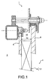
- FIG. 1 a portion of an illuminated glove box 1 according to a preferred embodiment of the present invention can be seen.
- This glove box 1 has a sealed enclosure 2 delimited by a plurality of walls 4, only one of which will be described below.
- the other undescribed walls could have an identical or similar design, or a different design, without departing from the scope of the invention.
- the wall 4 comprises first of all a partition made of polycarbonate 6, and more particularly Lexan ® , the inner face of this partition. 6 spaced apart from the partition 6, there is a biological protection partition 8 of the type made of lead glass or "Kyowaglas-XA ® ", this partition 8 being disposed externally with respect to the partition 6 and spaced therefrom by a spacing of the order of 40 mm, or even a lower value which can be lowered to 25 mm.
- One of the peculiarities of this invention lies in the design and implementation of lighting means of the sealed enclosure 2, these lighting means referenced 12 and shown partially and schematically on the figure 1 having the specificity of being provided with a lighting source housed in the inter-partition space 16 defined between the partitions 6 and 8. More precisely, it is the totality of a lighting module 14 of the means 12 which is housed in the inter-partition space 16, this module 14 being detailed on the Figures 2 to 4 which will now be described.
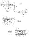
- the lighting means 12 comprise the lighting module 14 and an electronic ballast 18 supplying the light source 20 of the module 14, via a suitable wiring 22.
- the ballast 18 is connected by a wiring 24 to a power source (not shown).
- the lighting module 14 thus comprises the light source 20 preferably taking the form of a fluorescent tube, of a length which may for example reach 1 ⁇ m and having a diameter preferably of between 5 and 20 mm, for example 16 mm.
- the module 14 comprises a support body 28 preferably having a U-shaped section, and a length slightly greater than that of the tube 20 placed therein, as is visible on the Figures 2 to 4 .
- the support body 28 has a thickness substantially identical to the spacing 10, that is to say that the height of the two branches 30 of the U 28 is substantially equal to the same spacing 10 between the two partitions 6 and 8 Therefore, by being slid between these two partitions 6 and 8, the support body 28 can see the two free ends of the legs 30 of the U in contact with the polycarbonate partition 6, which allows to isolate the entire light source. 20 of the biological protection partition 8.
- the light-diffusing aperture 32 defined between the two branches 30 of the body 28, preferably made of aluminum and having a thickness of between 2 and 4 mm, is closed off. by the polycarbonate partition 6 on which the light emitted by the source 20 is almost not reflected.
- the minimum distance 34 between the light source 20 and the partition 6 is set to be preferably less than 10 mm, or even less than 5 mm.
- the ends of the U-shaped support body 28 are closed by end caps 36, implying that the only aperture through which the light can be emitted is the aperture 32 mentioned above, extending substantially the entire length of this body 28.
- the figure 4 shows that the light source 20 is mounted on the body 28 by support members 38 (only one being visible), one end of which allows the fluorescent tube 20 to be clipped, and whose other end is fixedly attached to the base of the U, for example by screwing.
- the support members 38 are spaced from each other in the direction of the tube 20 that they support.
- deflector means 40 are also fixedly attached to the base of the U 28, these deflecting means 40 also located in the space defined between the two legs 30 of the U 28 preferably taking the form of a mirror polishing steel sheet, folded so as to have an opening (not referenced) oriented towards the opening of diffusion 32, and thus towards the polycarbonate partition 6.
Landscapes
- Engineering & Computer Science (AREA)
- Physics & Mathematics (AREA)
- General Engineering & Computer Science (AREA)
- High Energy & Nuclear Physics (AREA)
- Robotics (AREA)
- Mechanical Engineering (AREA)
- Arrangement Of Elements, Cooling, Sealing, Or The Like Of Lighting Devices (AREA)
- Vehicle Step Arrangements And Article Storage (AREA)
- Manipulator (AREA)
- Devices For Use In Laboratory Experiments (AREA)
- Arrangements Of Lighting Devices For Vehicle Interiors, Mounting And Supporting Thereof, Circuits Therefore (AREA)
- Apparatus Associated With Microorganisms And Enzymes (AREA)
Description
- La présente invention se rapporte de façon générale au domaine des boîtes à gant à enceinte étanche éclairée.
- De l'art antérieur, on connaît une solution consistant à placer une ou plusieurs sources de lumière à l'intérieur de l'enceinte, cette solution se révélant très satisfaisante en terme de qualité d'éclairage obtenu. Néanmoins, il est souvent nécessaire de prévoir un dispositif d'éclairage à fort encombrement lorsque celui-ci est destiné à être logé au sein même de l'enceinte étanche, ce qui empêche son utilisation dans certains espaces de la boîte à gant ne présentant pas suffisamment de place libre pour accueillir un tel dispositif d'éclairage. Par ailleurs, dans un tel cas, la maintenance du dispositif est extrêmement difficile, et le traitement des déchets s'avère bien entendu lourd et onéreux.
Le documentWO 94/19922 - De l'art antérieur, on connaît également une solution consistant à placer une ou plusieurs sources de lumière à l'extérieur de l'enceinte, cette solution présentant l'avantage d'offrir une maintenance aisée et n'étant que peu contraignante en terme de traitement de déchets. Cependant, il a été remarqué que lorsqu'on place une source de lumière à l'extérieur de l'enceinte, à savoir derrière une paroi intégrant généralement une cloison en polycarbonate et une cloison de protection biologique espacée de celle-ci, la qualité de l'éclairage obtenu à l'intérieur de la boite à gant restait médiocre. En effet, cela s'explique en particulier par la création de reflets sur la cloison en polycarbonate ainsi que sur la cloison de protection biologique, rendant par conséquent l'éclairage particulièrement inefficace.
- Ainsi, pour répondre au moins partiellement aux problèmes susvisés, l'invention propose une boite à gant à enceinte étanche délimitée au moins partiellement par une paroi disposant d'une cloison en polycarbonate et d'une cloison de protection biologique espacée de la cloison en polycarbonate et agencée extérieurement par rapport à celle-ci, la boîte à gant comprenant en outre des moyens d'éclairage de l'enceinte, ces moyens d'éclairage comportant une source de lumière logée entre la cloison en polycarbonate et la cloison de protection biologique.
- Avec cette solution originale, il a été constaté que la qualité d'éclairage obtenue à l'intérieur de la boîte à gant était sensiblement identique à celle rencontrée avec les solutions de l'art antérieur dans lesquelles les moyens d'éclairage étaient situés au sein même de l'enceinte étanche. Cela s'explique par le fait que la disposition spécifique de la source de lumière entre la cloison en polycarbonate et la cloison de protection biologique limite fortement les reflets de la lumière sur cette cloison en polycarbonate en raison de la très forte proximité entre la source et cette même cloison, les reflets de la lumière sur la cloison de protection biologique pouvant quant à eux devenir quasi-inexistants.
- De plus, la source de lumière étant placée hors de l'enceinte étanche délimitée par la paroi en polycarbonate, de préférence en Lexan®, la maintenance est aisée et le traitement des déchets associés s'avère relativement simple, et donc peu onéreux.
- Il est indiqué que l'implantation de la source de lumière entre la cloison en polycarbonate et la cloison de protection biologique peut avantageusement être mise en oeuvre sur la quasi-totalité des parois de l'enceinte étanche, ce qui permet de limiter fortement les zones d'ombres à l'intérieur de celle-ci, comme cela était notamment le cas dans certaines zones dés boîtes à gant de l'art antérieur.
- Enfin, comme cela sera détaillé ci-dessous, les moyens d'éclairage peuvent de façon avantageuse être facilement réalisés à partir d'éléments simples et peu coûteux, ce qui rend ces moyens fortement optimisés en terme de coût de production.
- De préférence, la source de lumière est un tube fluorescent, à savoir une lampe à vapeur de mercure à basse pression dans laquelle la plus grande partie de la lumière est émise par une ou plusieurs couches de substances fluorescentes excitées par le rayonnement ultraviolet de la décharge. Le choix préférentiel du tube fluorescent a été retenu en raison de la très bonne perception de couleurs procurée, sans effet stroboscopique, et de sa température de fonctionnement peu élevée, ces avantages se révélant d'autant plus remarquables lorsque les moyens d'éclairage comprennent un ballast électronique pour l'alimentation de cette source de lumière. A cet égard, il est indiqué que la température de fonctionnement d'un tel tube peut avantageusement être de l'ordre de celle habituellement rencontrée avec les diodes électroluminescentes.
- La cloison de protection biologique est préférentiellement une cloison permettant d'atténuer les rayonnements gamma et/ou neutrons. De préférence, cette cloison de protection biologique est soit une cloison en verre dopé avec un absorbant neutrophage et/ou un absorbant dense, tel que le verre au plomb, soit une cloison en résine méthacrylique, comme le « Kyowaglas-XA® ».
- Il est naturellement prévu qu'un espacement entre la cloison en polycarbonate et la cloison de protection biologique soit de dimension suffisante pour que la source de lumière puisse être logée dans cet espace inter-cloison, cette dimension pouvant par exemple être de l'ordre de 40 mm, ou inférieure.
- De préférence, afin de réduire quasiment à néant les reflets de lumière sur la paroi de protection biologique et sur la paroi en polycarbonate, les moyens d'éclairage comprennent un corps support portant fixement la source de lumière et présentant une ouverture de diffusion de lumière obturée par la cloison en polycarbonate. Dans cette configuration, il ne se produit avantageusement aucun reflet de la lumière sur la cloison de protection biologique entièrement isolée de la source de lumière, la forte proximité entre cette source et la cloison en polycarbonate n'entraînant quasiment aucun reflet de lumière sur cette même cloison obturant l'ouverture du corps support de la source de lumière.
- Par ailleurs, les moyens d'éclairage comprennent de préférence également des moyens déflecteurs de lumière solidaires du corps support et situés à l'intérieur de celui-ci, les moyens déflecteurs orientant la lumière émise par la source de lumière vers la cloison en polycarbonate.
- A titre d'exemple indicatif, le corps support peut être un élément métallique de section en forme de U, avec dans ce cas de préférence les deux extrémités libres du U au contact de la cloison en polycarbonate. A titre informatif, il est noté que la forme de U est préférentiellement retenue en raison de sa facilité de fabrication.
- Enfin, pour obtenir une dissipation thermique la plus satisfaisante possible, le corps support est prévu en aluminium. Il a en effet été constaté que la température de fonctionnement de l'éclairage pouvait avantageusement être maintenue inférieure à 50°C, voire inférieure à 40°C dans le cas de l'emploi du « Kyowaglas-XA® » pour la réalisation de la protection biologique.
- D'autres avantages et caractéristiques de l'invention apparaîtront dans la description détaillée non limitative ci-dessous.
- Cette description sera faite au regard des dessins annexés parmi lesquels ;
- la
figure 1 représente une vue en coupe d'une partie de boîte à gant selon un mode de réalisation préféré de la présente invention ; - la
figure 2 représente une vue de côté des moyens d'éclairage équipant la boîte à gant montrée sur lafigure 1 ; - la
figure 3 représente une vue en coupe prise le long de la ligne III-III de lafigure 2 ; et - la
figure 4 représente une vue en coupe prise le long de la ligne IV-IV de lafigure 2 . - En référence tout d'abord à la
figure 1 , on peut apercevoir une partie d'une boîte à gant éclairée 1 selon un mode de réalisation préféré de la présente invention. Cette boîte à gant 1 présente une enceinte étanche 2 délimitée par une pluralité de parois 4, dont l'une seulement va être décrite ci-dessous. Cependant, il est noté que les autres parois non décrites pourraient disposer d'une conception identique ou similaire, ou bien d'une conception différente, sans sortir du cadre de l'invention. - La paroi 4 comporte tout d'abord une cloison en polycarbonate 6, et plus particulièrement en Lexan®, la face intérieure de cette cloison. 6 délimitant l'enceinte étanche 2. Espacée de cette cloison 6, se trouve une cloison de protection biologique 8 du type réalisée en verre au plomb ou en « Kyowaglas-XA® », cette cloison 8 étant disposée extérieurement par rapport à la cloison 6 et espacée de celle-ci d'un espacement 10 de l'ordre de 40 mm, voire d'une valeur inférieure pouvant être abaissée à 25 mm.
- Il est noté que la conception qui vient d'être décrite est connue de l'homme du métier, et correspond à celle fréquemment rencontrée sur les boîtes à gant existantes.
- L'une des particularités de là présente invention réside dans la conception et la mise en place de moyens d'éclairage de l'enceinte étanche 2, ces moyens d'éclairage référencés 12 et montrés partiellement et schématiquement sur la
figure 1 présentant la spécificité d'être munis d'une source d'éclairage logée dans l'espace inter-cloison 16 défini entre les cloisons 6 et 8. Plus précisément, c'est la totalité d'un module d'éclairage 14 des moyens 12 qui est logé dans l'espace inter-cloison 16, ce module 14 étant détaillé sur lesfigures 2 à 4 qui vont à présent être décrites. - En effet, les moyens d'éclairage 12 comprennent le module d'éclairage 14 ainsi qu'un ballast électronique 18 alimentant la source de lumière 20 du module 14, par l'intermédiaire d'un câblage approprié 22. A cet égard, il est précisé que le ballast 18 est quant à lui relié par un câblage 24 à une source d'énergie (non présentée).
- Le module d'éclairage 14 comprend donc la source de lumière 20 prenant de préférence la forme d'un tube fluorescent, d'une longueur pouvant par exemple atteindre 1, m et disposant d'un diamètre compris de préférence entre 5 et 20 mm, par exemple 16 mm.
- Pour assurer l'implantation de ce tube 20 dans l'espace inter-cloison 16, le module 14 comprend un corps support 28 présentant préférentiellement une section en forme de U, et de longueur légèrement supérieure à celle du tube 20 placé en son sein, comme cela est visible sur les
figures 2 à 4 . - Plus précisément, le corps support 28 présente une épaisseur sensiblement identique à l'espacement 10, c'est-à-dire que la hauteur des deux branches 30 du U 28 est sensiblement égale à ce même espacement 10 entre les deux cloisons 6 et 8. Par conséquent, en étant glissé entre ces deux cloisons 6 et 8, le corps support 28 peut voir les deux extrémités libres des branches 30 du U au contact de la cloison en polycarbonate 6, ce qui permet d'isoler entièrement la source de lumière 20 de la cloison de protection biologique 8. En d'autres termes, l'ouverture de diffusion de lumière 32 définie entre les deux branches 30 du corps 28 de préférence réalisé en aluminium et d'épaisseur comprise entre 2 et 4 mm, est obturée par la cloison en polycarbonate 6 sur laquelle la lumière émise par la source 20 ne se reflète quasiment pas. A ce titre, il est noté que la distance minimum 34 entre la source de lumière 20 et la cloison 6 est fixée de manière à être préférentiellement inférieure à 10 mm, voire inférieure à 5 mm.
- D'autre part, il est précisé que si le corps support 28 du module 14 est destiné à être introduit de façon glissée entre les.deux cloisons 6, 8 en prévoyant uniquement un jeu de montage entre ces éléments, des moyens additionnels peuvent néanmoins être prévus pour assurer la fixation rigide de ce corps 28 sur ces mêmes cloisons 6, 8. De préférence, des pattes de fixation empêchent tout mouvement du système d'éclairage en cas d'ouverture de la protection biologique, par exemple pour la vérification de non-présence de contamination.
- Comme cela est le mieux visible sur la
figure 2 , les extrémités du corps de support 28 en forme de U sont obturées par des embouts 36, impliquant que la seule ouverture à travers laquelle la lumière peut être émise est l'ouverture 32 mentionnée ci-dessus, s'étendant sensiblement sur toute la longueur de ce corps 28. - En outre, la
figure 4 montre que la source de lumière 20 est montée sur le corps 28 par des organes support 38 (un seul étant visible) dont une extrémité permet le clipsage du tube fluorescent 20, et dont l'autre extrémité est rapportée fixement sur la base du U, par exemple par vissage. Naturellement, les organes support 38 sont espacés les uns des autres dans la direction du tube 20 qu'ils supportent. - Enfin, il est précisé que pour diriger la lumière émise par la source 20 en direction de l'ouverture de diffusion 32, et donc vers la cloison 6, des moyens déflecteurs 40 sont également rapportés fixement sur la base du U 28, ces moyens déflecteurs 40 également situés dans l'espace défini entre les deux branches 30 du U 28 prenant de préférence la forme d'une tôle en acier à polissage du type miroir, repliée de façon à présenter une ouverture (non référencée) orientée vers l'ouverture de diffusion 32, et donc vers la cloison en polycarbonate 6.
- Bien entendu, diverses modifications peuvent être apportées par l'homme du métier à l'invention qui vient d'être décrite, uniquement à titre d'exemples non limitatifs.
Claims (12)
- Boîte à gant (1) à enceinte étanche (2) délimitée au moins partiellement par une paroi (4) disposant d'une cloison en polycarbonate (6) et d'une cloison de protection biologique (8) espacée de ladite cloison en polycarbonate (6) et agencée extérieurement par rapport à celle-ci, ladite boîte à gant comprenant en outre des moyens d'éclairage (12) de ladite enceinte, ces moyens d'éclairage comportant une source de lumière (20),
caractérisée en ce que ladite source de lumière (20) est logée entre ladite cloison en polycarbonate (6) et ladite cloison de protection biologique (8). - Boîte à gant (1) selon la revendication 1, caractérisée en ce que ladite source de lumière (20) est un tube fluorescent.
- Boîte à gant (1) selon la revendication 1 ou la revendication 2, caractérisée en ce que lesdits moyens d'éclairage (12) comprennent un ballast électronique (18) pour l'alimentation de ladite source de lumière .(20).
- Boîte à gant (1) selon l'une quelconque des revendications précédentes, caractérisée en ce que ladite cloison de protection biologique (8) est une cloison permettant d'atténuer les rayonnements gamma et/ou neutrons.
- Boîte à gant (1) selon la revendication 4, caractérisée en ce que ladite cloison de protection biologique (8) est une cloison en verre dopé avec un absorbant neutrophage et/ou un absorbant dense.
- Boîte à gant (1) selon la revendication 5, caractérisée en ce que ladite cloison de protection biologique (8) est une cloison en verre au plomb.
- Boîte à gant (1) selon la revendication 4, caractérisée en ce que ladite cloison de protection biologique (8) est une cloison en résine méthacrylique.
- Boîte à gant (1) selon l'une quelconque des revendications précédentes, caractérisée en ce que lesdits moyens d'éclairage (12) comprennent un corps support (28) portant fixement ladite source de lumière (20) et présentant une ouverture de diffusion de lumière (32) obturée par ladite cloison en polycarbonate (6).
- Boîte à gant (1) selon la revendication 8, caractérisée en ce que lesdits moyens d'éclairage (12) comprennent en outre des moyens déflecteurs de lumière (40) solidaires du corps support (28) et situés à l'intérieur de celui-ci, lesdits moyens déflecteurs (40) orientant ladite lumière émise par ladite source de lumière (20) vers ladite cloison en polycarbonate (6).
- Boîte à gant (1) selon la revendication 8 ou la revendication 9, caractérisée en ce que ledit corps support (28) est un élément métallique de section en forme de U.
- Boîte à gant (1) selon la revendication 10, caractérisée en ce que les deux extrémités libres (30) du U sont au contact de ladite cloison en polycarbonate (6).
- Boîte à gant (1) selon l'une quelconque des revendications 8 à 11, caractérisée en ce que ledit corps support (28) est en aluminium.
Applications Claiming Priority (2)
| Application Number | Priority Date | Filing Date | Title |
|---|---|---|---|
| FR0655059A FR2909024B1 (fr) | 2006-11-23 | 2006-11-23 | Boite a gant a enceinte etanche eclairee |
| PCT/EP2007/062585 WO2008061986A1 (fr) | 2006-11-23 | 2007-11-20 | Boite a gant a enceinte etanche eclairee |
Publications (2)
| Publication Number | Publication Date |
|---|---|
| EP2097227A1 EP2097227A1 (fr) | 2009-09-09 |
| EP2097227B1 true EP2097227B1 (fr) | 2010-05-12 |
Family
ID=38441529
Family Applications (1)
| Application Number | Title | Priority Date | Filing Date |
|---|---|---|---|
| EP07822757A Active EP2097227B1 (fr) | 2006-11-23 | 2007-11-20 | Boite a gant a enceinte etanche eclairee |
Country Status (9)
| Country | Link |
|---|---|
| US (1) | US8142044B2 (fr) |
| EP (1) | EP2097227B1 (fr) |
| JP (1) | JP5470045B2 (fr) |
| CN (1) | CN101535011B (fr) |
| AT (1) | ATE467490T1 (fr) |
| DE (1) | DE602007006552D1 (fr) |
| FR (1) | FR2909024B1 (fr) |
| RU (1) | RU2444431C2 (fr) |
| WO (1) | WO2008061986A1 (fr) |
Families Citing this family (8)
| Publication number | Priority date | Publication date | Assignee | Title |
|---|---|---|---|---|
| GB2473484A (en) * | 2009-09-14 | 2011-03-16 | Nuclear Decommissioning Authority | Glovebox port light |
| JP6075967B2 (ja) * | 2011-04-19 | 2017-02-08 | ベルゴニュークレール | 遮蔽保護テント組立体 |
| WO2014156135A1 (fr) * | 2013-03-29 | 2014-10-02 | パナソニックヘルスケア株式会社 | Isolateur, banc de nettoyage et armoire |
| WO2015046413A1 (fr) * | 2013-09-30 | 2015-04-02 | パナソニックヘルスケアホールディングス株式会社 | Chambre de travail |
| FR3027534B1 (fr) * | 2014-10-28 | 2016-12-30 | Getinge La Calhene | Solution d'eclairage d'une enceinte de confinement |
| CN109623881B (zh) * | 2018-12-26 | 2021-07-30 | 中国原子能科学研究院 | 用于手套箱的照明装置 |
| RU2751060C1 (ru) * | 2020-04-21 | 2021-07-07 | Федеральное казенное учреждение здравоохранения "Российский научно-исследовательский противочумный институт "Микроб" Федеральной службы по надзору в сфере защиты прав потребителей и благополучия человека (ФКУЗ "РосНИПЧИ "Микроб" Роспотребнадзора) | Мобильный бокс микробиологической безопасности |
| CN112077883A (zh) * | 2020-07-29 | 2020-12-15 | 中国原子能科学研究院 | 一种手套孔照明视窗一体化结构 |
Family Cites Families (28)
| Publication number | Priority date | Publication date | Assignee | Title |
|---|---|---|---|---|
| US2259147A (en) * | 1939-01-23 | 1941-10-14 | Seeger Refrigerator Co | Refrigerator illuminating means |
| US2576008A (en) * | 1949-09-09 | 1951-11-20 | Pangborn Corp | Wet blasting machine |
| US2816318A (en) * | 1953-03-17 | 1957-12-17 | American Motors Corp | Hinge for low-temperature cabinets |
| US3172994A (en) * | 1962-01-23 | 1965-03-09 | Kewaunee Mfg Company | Vacuum oven |
| US3612825A (en) * | 1969-08-08 | 1971-10-12 | Shatterproof Glass Corp | Windowed high-temperature ovens |
| US4059903A (en) * | 1976-03-31 | 1977-11-29 | Futurecraft Corporation | Controlled environment work enclosure |
| SU1263528A1 (ru) * | 1985-04-10 | 1986-10-15 | Ленинградский Ордена Ленина И Ордена Красного Знамени Механический Институт | Технологическа камера |
| US4697854A (en) * | 1985-10-25 | 1987-10-06 | Lunsford Thomas J | Portable enclosed hygenic workstation |
| SU1552514A1 (ru) * | 1988-02-01 | 1995-03-10 | Н.А. Кузнецов | Робототехнологическое устройство |
| JPH0637359Y2 (ja) * | 1988-04-20 | 1994-09-28 | 九八郎 ▲吉▼田 | 放射性物質分析用のグローブボックス |
| JPH0769462B2 (ja) * | 1989-12-01 | 1995-07-31 | 動力炉・核燃料開発事業団 | 放射線遮蔽構造 |
| GB9202154D0 (en) * | 1992-01-31 | 1992-03-18 | Challenger John G | Clean room construction |
| US5374116A (en) * | 1993-04-28 | 1994-12-20 | Fawn Engineering Co. | Anti-condensation product viewing window for a vending machine |
| DK85093D0 (da) * | 1993-07-16 | 1993-07-16 | Landsforeningen Til Kraeftens | Method and apparatus for performing operations |
| FR2741745B1 (fr) * | 1995-11-23 | 1998-02-20 | Neyrpic Framatome Mecanique | Dispositif de protection complementaire d'une enceinte de traitement de produits contamines |
| JPH09234253A (ja) * | 1996-02-29 | 1997-09-09 | Atom Medical Kk | 光線治療器 |
| JPH09269399A (ja) * | 1996-03-29 | 1997-10-14 | Nuclear Fuel Ind Ltd | グローブボックス |
| DE19722111C2 (de) * | 1996-05-28 | 2002-07-11 | Kobe Steel Ltd | Simulator für unterirdische Umgebungen |
| US6193391B1 (en) * | 1998-02-24 | 2001-02-27 | Osram Sylvania Inc. | Modular lamp assembly and method of assembling same |
| US6558020B1 (en) * | 1999-01-31 | 2003-05-06 | Walter Holzer | Flat reflector lamp for fluorescent tubes |
| US6297047B1 (en) * | 1999-08-25 | 2001-10-02 | Spx Corporation | Ultraviolet sterilization of CO2 cell-culture incubator internal environments |
| US6361181B1 (en) * | 2000-02-28 | 2002-03-26 | Maytag Corporation | Appliance with light mounted in door |
| ATE468511T1 (de) * | 2001-02-23 | 2010-06-15 | Koninkl Philips Electronics Nv | Leuchte |
| US20040168341A1 (en) * | 2001-03-21 | 2004-09-02 | Petersen Peter Mosborg | Methods for performing operations, a housing for such methods, and furnishings for such housing |
| FR2827490B1 (fr) * | 2001-07-19 | 2003-10-17 | Chanel | Presentoir lumineux transformable |
| US20030070404A1 (en) * | 2001-10-12 | 2003-04-17 | Gerry Calabrese | Glove box contamination-proof mail handling |
| JP2004279308A (ja) * | 2003-03-18 | 2004-10-07 | Mitsui Eng & Shipbuild Co Ltd | グローブボックス用グローブポート |
| US7818782B2 (en) * | 2004-04-14 | 2010-10-19 | Dai Nippon Printing Co., Ltd. | Authentication medium, authenticable substrate, authentication medium label, authentication medium transfer sheet, authenticable sheet, and authenticable information recording medium |
-
2006
- 2006-11-23 FR FR0655059A patent/FR2909024B1/fr not_active Expired - Fee Related
-
2007
- 2007-11-20 CN CN2007800419579A patent/CN101535011B/zh not_active Expired - Fee Related
- 2007-11-20 EP EP07822757A patent/EP2097227B1/fr active Active
- 2007-11-20 JP JP2009537621A patent/JP5470045B2/ja active Active
- 2007-11-20 RU RU2009123826/02A patent/RU2444431C2/ru not_active IP Right Cessation
- 2007-11-20 DE DE602007006552T patent/DE602007006552D1/de active Active
- 2007-11-20 WO PCT/EP2007/062585 patent/WO2008061986A1/fr not_active Ceased
- 2007-11-20 US US12/513,247 patent/US8142044B2/en not_active Expired - Fee Related
- 2007-11-20 AT AT07822757T patent/ATE467490T1/de not_active IP Right Cessation
Also Published As
| Publication number | Publication date |
|---|---|
| FR2909024A1 (fr) | 2008-05-30 |
| WO2008061986A1 (fr) | 2008-05-29 |
| EP2097227A1 (fr) | 2009-09-09 |
| US20100060119A1 (en) | 2010-03-11 |
| JP2010510508A (ja) | 2010-04-02 |
| ATE467490T1 (de) | 2010-05-15 |
| CN101535011B (zh) | 2011-06-08 |
| CN101535011A (zh) | 2009-09-16 |
| FR2909024B1 (fr) | 2009-02-13 |
| JP5470045B2 (ja) | 2014-04-16 |
| DE602007006552D1 (de) | 2010-06-24 |
| RU2444431C2 (ru) | 2012-03-10 |
| US8142044B2 (en) | 2012-03-27 |
| RU2009123826A (ru) | 2010-12-27 |
Similar Documents
| Publication | Publication Date | Title |
|---|---|---|
| EP2097227A1 (fr) | Boite a gant a enceinte etanche eclairee | |
| EP2940375A1 (fr) | Dispositif d'atténuation de perturbations électromagnétiques, et module lumineux de véhicule automobile équipé d'un tel dispositif | |
| FR3001027A1 (fr) | Module d'eclairage et procede de montage d'un tel module | |
| EP2886942A1 (fr) | Dispositif d'éclairage | |
| EP4726255A2 (fr) | Module lumineux imageant la surface eclairee d'un collecteur avec bloqueur de rayons parasites | |
| FR2537249A1 (fr) | Projecteur a faisceau coupe a reflecteur elliptique pour vehicule automobile | |
| FR2794218A1 (fr) | Feu de signalisation pour vehicule automobile | |
| EP3899361B1 (fr) | Elément lumineux de pièce de carrosserie en polycarbonate injecté | |
| FR2934356A1 (fr) | Dispositif de support d'un systeme d'eclairage amovible et autoporte pour hublot. | |
| EP2926049A1 (fr) | Dispositif de signalisation pour véhicule avec effet tridimensionnel | |
| FR2461889A1 (fr) | Projecteur etanche a lampe interchangeable | |
| EP3416465B1 (fr) | ENSEMBLE COMPORTANT UN BOITIER AVANT, UN BOITIER ARRIÈRE, ET UNE CARTE ÉLECTRONIQUE DESTINÉE A ÊTRE FIXÉE ENTRE LE BOITIER AVANT ET UN BOITIER ARRiÈRE | |
| FR2908861A1 (fr) | Colonne lumineuse a zone lumineuse positionnable et de hauteur de colonne ajustable | |
| WO2020174140A1 (fr) | Dispositif lumineux d'éclairage pour véhicule automobile doté d'un réflecteur muni d'ailettes de refroidissement | |
| FR2687762A1 (fr) | Projecteur a lentille equipe de moyens de montage de la lentille perfectionnes. | |
| FR3138183A1 (fr) | Dispositif lumineux pour véhicule automobile. | |
| FR2687761A1 (fr) | Projecteur comportant des moyens perfectionnes d'arret de certaines parties du rayonnement, notamment pour vehicule automobiles. | |
| BE1012778A6 (fr) | Dispositif d'eclairage. | |
| EP1544538B1 (fr) | Dispositif projecteur avec porte-lampe | |
| FR2928616A1 (fr) | Procede de montage d'une unite de signalisation destinee a equiper un vehicule d'une fonction de recul ou d'une fonction anti-brouillard | |
| EP2479488A1 (fr) | Dispositif d'éclairage et/ou de signalisation comportant un élément convertisseur d'énergie | |
| FR3137742A3 (fr) | Dispositif lumineux automobile | |
| FR2671391A1 (fr) | Dispositif d'eclairage pour enseigne et enseigne comportant un tel dispositif. | |
| FR3085639A1 (fr) | Dispositif de recouvrement d’un compartiment a bagages de vehicule automobile | |
| FR3125104A1 (fr) | Module lumineux comprenant un élément à taux variable de transmission de lumière |
Legal Events
| Date | Code | Title | Description |
|---|---|---|---|
| PUAI | Public reference made under article 153(3) epc to a published international application that has entered the european phase |
Free format text: ORIGINAL CODE: 0009012 |
|
| 17P | Request for examination filed |
Effective date: 20090514 |
|
| AK | Designated contracting states |
Kind code of ref document: A1 Designated state(s): AT BE BG CH CY CZ DE DK EE ES FI FR GB GR HU IE IS IT LI LT LU LV MC MT NL PL PT RO SE SI SK TR |
|
| GRAP | Despatch of communication of intention to grant a patent |
Free format text: ORIGINAL CODE: EPIDOSNIGR1 |
|
| GRAC | Information related to communication of intention to grant a patent modified |
Free format text: ORIGINAL CODE: EPIDOSCIGR1 |
|
| DAX | Request for extension of the european patent (deleted) | ||
| GRAC | Information related to communication of intention to grant a patent modified |
Free format text: ORIGINAL CODE: EPIDOSCIGR1 |
|
| GRAS | Grant fee paid |
Free format text: ORIGINAL CODE: EPIDOSNIGR3 |
|
| GRAA | (expected) grant |
Free format text: ORIGINAL CODE: 0009210 |
|
| AK | Designated contracting states |
Kind code of ref document: B1 Designated state(s): AT BE BG CH CY CZ DE DK EE ES FI FR GB GR HU IE IS IT LI LT LU LV MC MT NL PL PT RO SE SI SK TR |
|
| REG | Reference to a national code |
Ref country code: GB Ref legal event code: FG4D Free format text: NOT ENGLISH |
|
| REG | Reference to a national code |
Ref country code: CH Ref legal event code: EP |
|
| REG | Reference to a national code |
Ref country code: IE Ref legal event code: FG4D Free format text: LANGUAGE OF EP DOCUMENT: FRENCH |
|
| REF | Corresponds to: |
Ref document number: 602007006552 Country of ref document: DE Date of ref document: 20100624 Kind code of ref document: P |
|
| REG | Reference to a national code |
Ref country code: SE Ref legal event code: TRGR |
|
| REG | Reference to a national code |
Ref country code: NL Ref legal event code: VDEP Effective date: 20100512 |
|
| LTIE | Lt: invalidation of european patent or patent extension |
Effective date: 20100512 |
|
| PG25 | Lapsed in a contracting state [announced via postgrant information from national office to epo] |
Ref country code: LT Free format text: LAPSE BECAUSE OF FAILURE TO SUBMIT A TRANSLATION OF THE DESCRIPTION OR TO PAY THE FEE WITHIN THE PRESCRIBED TIME-LIMIT Effective date: 20100512 Ref country code: NL Free format text: LAPSE BECAUSE OF FAILURE TO SUBMIT A TRANSLATION OF THE DESCRIPTION OR TO PAY THE FEE WITHIN THE PRESCRIBED TIME-LIMIT Effective date: 20100512 Ref country code: ES Free format text: LAPSE BECAUSE OF FAILURE TO SUBMIT A TRANSLATION OF THE DESCRIPTION OR TO PAY THE FEE WITHIN THE PRESCRIBED TIME-LIMIT Effective date: 20100823 |
|
| PG25 | Lapsed in a contracting state [announced via postgrant information from national office to epo] |
Ref country code: FI Free format text: LAPSE BECAUSE OF FAILURE TO SUBMIT A TRANSLATION OF THE DESCRIPTION OR TO PAY THE FEE WITHIN THE PRESCRIBED TIME-LIMIT Effective date: 20100512 Ref country code: SI Free format text: LAPSE BECAUSE OF FAILURE TO SUBMIT A TRANSLATION OF THE DESCRIPTION OR TO PAY THE FEE WITHIN THE PRESCRIBED TIME-LIMIT Effective date: 20100512 Ref country code: AT Free format text: LAPSE BECAUSE OF FAILURE TO SUBMIT A TRANSLATION OF THE DESCRIPTION OR TO PAY THE FEE WITHIN THE PRESCRIBED TIME-LIMIT Effective date: 20100512 Ref country code: LV Free format text: LAPSE BECAUSE OF FAILURE TO SUBMIT A TRANSLATION OF THE DESCRIPTION OR TO PAY THE FEE WITHIN THE PRESCRIBED TIME-LIMIT Effective date: 20100512 Ref country code: IS Free format text: LAPSE BECAUSE OF FAILURE TO SUBMIT A TRANSLATION OF THE DESCRIPTION OR TO PAY THE FEE WITHIN THE PRESCRIBED TIME-LIMIT Effective date: 20100912 |
|
| REG | Reference to a national code |
Ref country code: IE Ref legal event code: FD4D |
|
| PG25 | Lapsed in a contracting state [announced via postgrant information from national office to epo] |
Ref country code: CY Free format text: LAPSE BECAUSE OF FAILURE TO SUBMIT A TRANSLATION OF THE DESCRIPTION OR TO PAY THE FEE WITHIN THE PRESCRIBED TIME-LIMIT Effective date: 20100616 Ref country code: PL Free format text: LAPSE BECAUSE OF FAILURE TO SUBMIT A TRANSLATION OF THE DESCRIPTION OR TO PAY THE FEE WITHIN THE PRESCRIBED TIME-LIMIT Effective date: 20100512 |
|
| PG25 | Lapsed in a contracting state [announced via postgrant information from national office to epo] |
Ref country code: PT Free format text: LAPSE BECAUSE OF FAILURE TO SUBMIT A TRANSLATION OF THE DESCRIPTION OR TO PAY THE FEE WITHIN THE PRESCRIBED TIME-LIMIT Effective date: 20100913 Ref country code: EE Free format text: LAPSE BECAUSE OF FAILURE TO SUBMIT A TRANSLATION OF THE DESCRIPTION OR TO PAY THE FEE WITHIN THE PRESCRIBED TIME-LIMIT Effective date: 20100512 Ref country code: IE Free format text: LAPSE BECAUSE OF FAILURE TO SUBMIT A TRANSLATION OF THE DESCRIPTION OR TO PAY THE FEE WITHIN THE PRESCRIBED TIME-LIMIT Effective date: 20100512 Ref country code: DK Free format text: LAPSE BECAUSE OF FAILURE TO SUBMIT A TRANSLATION OF THE DESCRIPTION OR TO PAY THE FEE WITHIN THE PRESCRIBED TIME-LIMIT Effective date: 20100512 |
|
| PG25 | Lapsed in a contracting state [announced via postgrant information from national office to epo] |
Ref country code: SK Free format text: LAPSE BECAUSE OF FAILURE TO SUBMIT A TRANSLATION OF THE DESCRIPTION OR TO PAY THE FEE WITHIN THE PRESCRIBED TIME-LIMIT Effective date: 20100512 Ref country code: RO Free format text: LAPSE BECAUSE OF FAILURE TO SUBMIT A TRANSLATION OF THE DESCRIPTION OR TO PAY THE FEE WITHIN THE PRESCRIBED TIME-LIMIT Effective date: 20100512 Ref country code: CZ Free format text: LAPSE BECAUSE OF FAILURE TO SUBMIT A TRANSLATION OF THE DESCRIPTION OR TO PAY THE FEE WITHIN THE PRESCRIBED TIME-LIMIT Effective date: 20100512 |
|
| PLBE | No opposition filed within time limit |
Free format text: ORIGINAL CODE: 0009261 |
|
| STAA | Information on the status of an ep patent application or granted ep patent |
Free format text: STATUS: NO OPPOSITION FILED WITHIN TIME LIMIT |
|
| PG25 | Lapsed in a contracting state [announced via postgrant information from national office to epo] |
Ref country code: IT Free format text: LAPSE BECAUSE OF FAILURE TO SUBMIT A TRANSLATION OF THE DESCRIPTION OR TO PAY THE FEE WITHIN THE PRESCRIBED TIME-LIMIT Effective date: 20100512 |
|
| 26N | No opposition filed |
Effective date: 20110215 |
|
| PG25 | Lapsed in a contracting state [announced via postgrant information from national office to epo] |
Ref country code: GR Free format text: LAPSE BECAUSE OF FAILURE TO SUBMIT A TRANSLATION OF THE DESCRIPTION OR TO PAY THE FEE WITHIN THE PRESCRIBED TIME-LIMIT Effective date: 20100813 |
|
| REG | Reference to a national code |
Ref country code: DE Ref legal event code: R097 Ref document number: 602007006552 Country of ref document: DE Effective date: 20110214 |
|
| PG25 | Lapsed in a contracting state [announced via postgrant information from national office to epo] |
Ref country code: MC Free format text: LAPSE BECAUSE OF NON-PAYMENT OF DUE FEES Effective date: 20101130 |
|
| PG25 | Lapsed in a contracting state [announced via postgrant information from national office to epo] |
Ref country code: MT Free format text: LAPSE BECAUSE OF FAILURE TO SUBMIT A TRANSLATION OF THE DESCRIPTION OR TO PAY THE FEE WITHIN THE PRESCRIBED TIME-LIMIT Effective date: 20100512 |
|
| REG | Reference to a national code |
Ref country code: CH Ref legal event code: PL |
|
| PG25 | Lapsed in a contracting state [announced via postgrant information from national office to epo] |
Ref country code: CH Free format text: LAPSE BECAUSE OF NON-PAYMENT OF DUE FEES Effective date: 20111130 Ref country code: LI Free format text: LAPSE BECAUSE OF NON-PAYMENT OF DUE FEES Effective date: 20111130 |
|
| PG25 | Lapsed in a contracting state [announced via postgrant information from national office to epo] |
Ref country code: LU Free format text: LAPSE BECAUSE OF NON-PAYMENT OF DUE FEES Effective date: 20101120 Ref country code: HU Free format text: LAPSE BECAUSE OF FAILURE TO SUBMIT A TRANSLATION OF THE DESCRIPTION OR TO PAY THE FEE WITHIN THE PRESCRIBED TIME-LIMIT Effective date: 20101113 Ref country code: BG Free format text: LAPSE BECAUSE OF FAILURE TO SUBMIT A TRANSLATION OF THE DESCRIPTION OR TO PAY THE FEE WITHIN THE PRESCRIBED TIME-LIMIT Effective date: 20100512 |
|
| PG25 | Lapsed in a contracting state [announced via postgrant information from national office to epo] |
Ref country code: TR Free format text: LAPSE BECAUSE OF FAILURE TO SUBMIT A TRANSLATION OF THE DESCRIPTION OR TO PAY THE FEE WITHIN THE PRESCRIBED TIME-LIMIT Effective date: 20100512 |
|
| PG25 | Lapsed in a contracting state [announced via postgrant information from national office to epo] |
Ref country code: BG Free format text: LAPSE BECAUSE OF FAILURE TO SUBMIT A TRANSLATION OF THE DESCRIPTION OR TO PAY THE FEE WITHIN THE PRESCRIBED TIME-LIMIT Effective date: 20100812 |
|
| PGFP | Annual fee paid to national office [announced via postgrant information from national office to epo] |
Ref country code: DE Payment date: 20131106 Year of fee payment: 7 Ref country code: SE Payment date: 20131108 Year of fee payment: 7 |
|
| PGFP | Annual fee paid to national office [announced via postgrant information from national office to epo] |
Ref country code: BE Payment date: 20131128 Year of fee payment: 7 |
|
| REG | Reference to a national code |
Ref country code: DE Ref legal event code: R119 Ref document number: 602007006552 Country of ref document: DE |
|
| PG25 | Lapsed in a contracting state [announced via postgrant information from national office to epo] |
Ref country code: BE Free format text: LAPSE BECAUSE OF NON-PAYMENT OF DUE FEES Effective date: 20141130 |
|
| REG | Reference to a national code |
Ref country code: SE Ref legal event code: EUG |
|
| PG25 | Lapsed in a contracting state [announced via postgrant information from national office to epo] |
Ref country code: SE Free format text: LAPSE BECAUSE OF NON-PAYMENT OF DUE FEES Effective date: 20141121 |
|
| PG25 | Lapsed in a contracting state [announced via postgrant information from national office to epo] |
Ref country code: DE Free format text: LAPSE BECAUSE OF NON-PAYMENT OF DUE FEES Effective date: 20150602 |
|
| REG | Reference to a national code |
Ref country code: FR Ref legal event code: PLFP Year of fee payment: 9 |
|
| REG | Reference to a national code |
Ref country code: FR Ref legal event code: PLFP Year of fee payment: 10 |
|
| REG | Reference to a national code |
Ref country code: FR Ref legal event code: PLFP Year of fee payment: 11 |
|
| REG | Reference to a national code |
Ref country code: GB Ref legal event code: 732E Free format text: REGISTERED BETWEEN 20220217 AND 20220223 |
|
| PGFP | Annual fee paid to national office [announced via postgrant information from national office to epo] |
Ref country code: GB Payment date: 20241120 Year of fee payment: 18 |
|
| PGFP | Annual fee paid to national office [announced via postgrant information from national office to epo] |
Ref country code: FR Payment date: 20241121 Year of fee payment: 18 |