EP2097277B1 - Aufhängungsvorrichtung für ein fahrzeug - Google Patents
Aufhängungsvorrichtung für ein fahrzeug Download PDFInfo
- Publication number
- EP2097277B1 EP2097277B1 EP08720744A EP08720744A EP2097277B1 EP 2097277 B1 EP2097277 B1 EP 2097277B1 EP 08720744 A EP08720744 A EP 08720744A EP 08720744 A EP08720744 A EP 08720744A EP 2097277 B1 EP2097277 B1 EP 2097277B1
- Authority
- EP
- European Patent Office
- Prior art keywords
- wheel
- side attachment
- main
- vehicle
- main portion
- Prior art date
- Legal status (The legal status is an assumption and is not a legal conclusion. Google has not performed a legal analysis and makes no representation as to the accuracy of the status listed.)
- Not-in-force
Links
- 239000000725 suspension Substances 0.000 title claims abstract description 260
- 230000005489 elastic deformation Effects 0.000 claims description 48
- 230000007935 neutral effect Effects 0.000 claims description 38
- 239000000463 material Substances 0.000 claims description 14
- 238000013016 damping Methods 0.000 description 25
- 230000008859 change Effects 0.000 description 17
- 238000005452 bending Methods 0.000 description 13
- 239000006096 absorbing agent Substances 0.000 description 10
- 230000035939 shock Effects 0.000 description 10
- 230000008901 benefit Effects 0.000 description 7
- 238000010276 construction Methods 0.000 description 6
- 238000006073 displacement reaction Methods 0.000 description 5
- 230000033001 locomotion Effects 0.000 description 5
- 230000005540 biological transmission Effects 0.000 description 4
- 230000003247 decreasing effect Effects 0.000 description 4
- 238000000034 method Methods 0.000 description 4
- 239000002131 composite material Substances 0.000 description 2
- 230000000694 effects Effects 0.000 description 2
- 239000007769 metal material Substances 0.000 description 2
- 239000007787 solid Substances 0.000 description 2
- 238000013519 translation Methods 0.000 description 2
- 230000014616 translation Effects 0.000 description 2
- 238000012935 Averaging Methods 0.000 description 1
- 229910000639 Spring steel Inorganic materials 0.000 description 1
- 230000009471 action Effects 0.000 description 1
- 238000009826 distribution Methods 0.000 description 1
- 230000001747 exhibiting effect Effects 0.000 description 1
- 238000002474 experimental method Methods 0.000 description 1
- 239000012530 fluid Substances 0.000 description 1
- 230000005484 gravity Effects 0.000 description 1
- 238000004519 manufacturing process Methods 0.000 description 1
- 239000011347 resin Substances 0.000 description 1
- 229920005989 resin Polymers 0.000 description 1
- 230000004044 response Effects 0.000 description 1
- 238000005096 rolling process Methods 0.000 description 1
Images



Classifications
-
- B—PERFORMING OPERATIONS; TRANSPORTING
- B60—VEHICLES IN GENERAL
- B60G—VEHICLE SUSPENSION ARRANGEMENTS
- B60G3/00—Resilient suspensions for a single wheel
- B60G3/02—Resilient suspensions for a single wheel with a single pivoted arm
- B60G3/04—Resilient suspensions for a single wheel with a single pivoted arm the arm being essentially transverse to the longitudinal axis of the vehicle
- B60G3/10—Resilient suspensions for a single wheel with a single pivoted arm the arm being essentially transverse to the longitudinal axis of the vehicle the arm itself being resilient, e.g. leaf spring
-
- B—PERFORMING OPERATIONS; TRANSPORTING
- B60—VEHICLES IN GENERAL
- B60G—VEHICLE SUSPENSION ARRANGEMENTS
- B60G11/00—Resilient suspensions characterised by arrangement, location or kind of springs
- B60G11/32—Resilient suspensions characterised by arrangement, location or kind of springs having springs of different kinds
- B60G11/48—Resilient suspensions characterised by arrangement, location or kind of springs having springs of different kinds not including leaf springs
- B60G11/50—Resilient suspensions characterised by arrangement, location or kind of springs having springs of different kinds not including leaf springs having helical, spiral or coil springs, and also torsion-bar springs
-
- B—PERFORMING OPERATIONS; TRANSPORTING
- B60—VEHICLES IN GENERAL
- B60G—VEHICLE SUSPENSION ARRANGEMENTS
- B60G7/00—Pivoted suspension arms; Accessories thereof
- B60G7/001—Suspension arms, e.g. constructional features
-
- B—PERFORMING OPERATIONS; TRANSPORTING
- B60—VEHICLES IN GENERAL
- B60G—VEHICLE SUSPENSION ARRANGEMENTS
- B60G2200/00—Indexing codes relating to suspension types
- B60G2200/40—Indexing codes relating to the wheels in the suspensions
- B60G2200/46—Indexing codes relating to the wheels in the suspensions camber angle
-
- B—PERFORMING OPERATIONS; TRANSPORTING
- B60—VEHICLES IN GENERAL
- B60G—VEHICLE SUSPENSION ARRANGEMENTS
- B60G2200/00—Indexing codes relating to suspension types
- B60G2200/40—Indexing codes relating to the wheels in the suspensions
- B60G2200/462—Toe-in/out
-
- B—PERFORMING OPERATIONS; TRANSPORTING
- B60—VEHICLES IN GENERAL
- B60G—VEHICLE SUSPENSION ARRANGEMENTS
- B60G2202/00—Indexing codes relating to the type of spring, damper or actuator
- B60G2202/10—Type of spring
- B60G2202/11—Leaf spring
- B60G2202/116—Leaf spring having a "C" form loaded only at its ends transversally to its central axis
-
- B—PERFORMING OPERATIONS; TRANSPORTING
- B60—VEHICLES IN GENERAL
- B60G—VEHICLE SUSPENSION ARRANGEMENTS
- B60G2202/00—Indexing codes relating to the type of spring, damper or actuator
- B60G2202/10—Type of spring
- B60G2202/13—Torsion spring
-
- B—PERFORMING OPERATIONS; TRANSPORTING
- B60—VEHICLES IN GENERAL
- B60G—VEHICLE SUSPENSION ARRANGEMENTS
- B60G2204/00—Indexing codes related to suspensions per se or to auxiliary parts
- B60G2204/10—Mounting of suspension elements
- B60G2204/14—Mounting of suspension arms
- B60G2204/148—Mounting of suspension arms on the unsprung part of the vehicle, e.g. wheel knuckle or rigid axle
-
- B—PERFORMING OPERATIONS; TRANSPORTING
- B60—VEHICLES IN GENERAL
- B60G—VEHICLE SUSPENSION ARRANGEMENTS
- B60G2204/00—Indexing codes related to suspensions per se or to auxiliary parts
- B60G2204/10—Mounting of suspension elements
- B60G2204/30—In-wheel mountings
-
- B—PERFORMING OPERATIONS; TRANSPORTING
- B60—VEHICLES IN GENERAL
- B60G—VEHICLE SUSPENSION ARRANGEMENTS
- B60G2206/00—Indexing codes related to the manufacturing of suspensions: constructional features, the materials used, procedures or tools
- B60G2206/01—Constructional features of suspension elements, e.g. arms, dampers, springs
- B60G2206/10—Constructional features of arms
- B60G2206/12—Constructional features of arms with two attachment points on the sprung part of the vehicle
-
- B—PERFORMING OPERATIONS; TRANSPORTING
- B60—VEHICLES IN GENERAL
- B60G—VEHICLE SUSPENSION ARRANGEMENTS
- B60G2206/00—Indexing codes related to the manufacturing of suspensions: constructional features, the materials used, procedures or tools
- B60G2206/01—Constructional features of suspension elements, e.g. arms, dampers, springs
- B60G2206/10—Constructional features of arms
- B60G2206/15—Constructional features of arms the arm being resilient
Definitions
- the present invention relates to a suspension apparatus for a vehicle, and particularly to the art of simplifying a construction of the suspension apparatus.
- a suspension device for a vehicle is provided between a body, and a wheel, of the vehicle so that the body is supported by the wheel, the transmission of vibration of the wheel to the body is minimized, and the position of the wheel relative to the body is bound as desired.
- various sorts of suspension devices There have conventionally been used various sorts of suspension devices.
- each suspension device cannot avoid having a complicated construction, because the suspension device is essentially required to achieve the above-indicated aims.
- the simplification of construction of the suspension device has been proposed by each of the following four patent documents: Japanese
- Patent Application Publication No. 2000-177346 Japanese Patent Application Publication No. 3-266783 , Japanese Patent Application Publication No. 7-89312 , and Japanese Patent Application Publication No. 2005-225258 .
- an elastic-deformation capability of a suspension link is so increased that the suspension link also functions as a spring member. Otherwise, a shape of a spring member is improved.
- FR-A1-2810927 discloses a suspension apparatus for a vehicle which utilises an elongate element as both a suspension member and a spring.
- the elongate element is generally D-shaped with the wheel hub connected to the straight side of the D. Opposite ends of the elongate member are connected to the vehicle at positions close to each other by pivotable connections.
- EP-A2-1422081 discloses a trailing arm vehicle suspension with a plate-like lower arm pivotally mounted to the vehicle body. It utilises a conventional spring and shock absorber separate from the suspension arm.
- FR-A1-2787389 discloses a suspension arrangement for a vehicle in which the wheel hubs are each mounted to the four ends of a generally X-shaped member forming the chassis for the vehicle.
- the arms of the chassis form both suspension elements and springs and the remote ends of the chassis, to which the hubs are mounted, are connected to the vehicle body by laterally extending straight elements integral with the chassis.
- GB-A-2010759 discloses a torsion bar suspension element for a vehicle, the suspension element being generally triangular.
- GB-A-1517665 discloses a strut type suspension arrangement for a vehicle wheel in which the hub is mounted to two elongate struts, each being pivotally mounted to the vehicle on pivot axes which are inclined relative to each other.
- GB-A-2375744 discloses the use of a composite member to replace the upper and lower control arms, coil springs and anti roll bar of a conventional suspension system.
- the composite member extends transversely of the vehicle and is connected to wheel hubs on opposite lateral sides of the vehicle.
- WO-A2-2007/113761 which is prior art by virtue of Article 54(3) EPC, discloses a suspension system for a vehicle which utilises a lower arm which comprises a pair of transverse rods articulated at their outer ends to the wheel hub and at their inner ends to the vehicle by pivotal axes which are inclined to each other, the transverse rods being connected together by blade-like elements to control their bending stiffness.
- the suspension device can be improved with respect to its various features.
- It is therefore an object of the present invention is to provide a novel suspension apparatus for a vehicle that not only meets various requirements but also enjoys a simple construction.
- the main suspension member includes the main portion which is formed of the elongate material such that the opposite ends of the main portion are near to each other.
- the elongate material constituting the main portion can be long enough to have a sufficiently high elastic-deformation capability, but nonetheless the main portion as a whole can be provided in a considerably small space.
- the first and second body-side attachment portions that are respectively provided at the opposite ends of the main portion are attached to the body of the vehicle such that the first and second attachment portions are respectively pivotable about the first and second pivotal axes, each relative to the body of the vehicle.
- main portion of the single elongate material such that the main portion is smoothly curved to have a generally C-shaped profile, because the concentration of stresses produced therein can be avoided and the manufacturing thereof can be facilitated.
- the elongate material may be a metallic material such as a spring material, or a non-metallic material such as a fiber-reinforced resin.
- the first and second body-side attachment portions are preferably offset from each other in a direction having a directional component perpendicular to one of the first and second pivotal axes.
- each of the first and second body-side attachment portions needs to have a certain size so as to have a certain degree of strength.
- the distance between the two body-side attachment portions cannot be decreased beyond a certain amount so as to avoid the interference of the two attachment portions with each other.
- the first and second body-side attachment portions are offset from each other in the direction having the directional component perpendicular to one of the first and second pivotal axes, so as to avoid the interference of the two attachment portions with each other. Therefore, the distance between the two body-side attachment portions in the direction perpendicular to the first and second pivotal axes can be decreased to a sufficiently small value.
- the first and second pivotal axes are preferably inclined relative to each other.
- the main portion Since the first and second pivotal axes are inclined relative to each other, the main portion is subjected to a twisting elastic deformation, when the first and second body-side attachment portions are pivoted.
- a twisting elastic deformation For example, if respective pivotal centers of the first and second body-side attachment portions (i.e., respective intersection points where the first and second pivotal axes intersect two extension lines extended from opposite ends of a neutral axis of the main portion, respectively) are not offset from each other, the main portion is mainly subjected to a twisting elastic deformation (though the main portion is also subjected to a bending elastic deformation to some extent).
- the main portion is apparently subjected to a complicated elastic deformation including the twisting and bending elastic deformations. That is, the elastic-deformation capability of the main portion can be more efficiently utilized. In addition, the twisting elastic deformation of the main portion can be effectively utilized to obtain desired changes of the alignment of the wheel.
- first and second pivotal axes are parallel to each other, it can be easily understood that the first and second body-side attachment portions are pivoted about the first and second pivotal axes, respectively.
- first and second pivotal axes are inclined relative to each other, it cannot be easily understood how the first and second body-side attachment portions are pivoted.
- a first and a second intersection point where the first and second pivotal axes intersect the two extension lines extended from the opposite ends of the neutral axis of the main portion, respectively are regarded as the respective pivotal centers of the first and second body-side attachment portions. That is, it can be said that the main suspension member is pivoted about a single straight line that passes through the first and second intersection points.
- a relative-positional relationship between the first and second body-side attachment portions and the main portion is pre-determined such that the first and second pivotal axes intersect the two extension lines extended from the neutral axis of the main portion, respectively.
- first and second pivotal axes intersect the two extension lines, respectively.
- each of the first and second pivotal axes crosses, in a three-dimensional space, over a corresponding one of the two extension lines, with a short distance left therebetween.
- a point on each pivotal axis that is the nearest to the corresponding extension line of the neutral axis can be regarded as an intersection point.
- first and second pivotal axes are inclined relative to each other.
- first and second pivotal axes may be inclined relative to each other, in a view taken in a front-rear direction of the vehicle's body.
- first and second pivotal axes are inclined relative to each other in a plan view, more advantageous changes of the alignment of the wheel can be realized by the suspension apparatus.
- a first intersection point and a second intersection point where the first and second pivotal axes respectively intersect two extension lines which are respectively extended from opposite ends of a neutral axis of the main portion are offset from an extension line extended from the second pivotal axis, and an extension line extended from the first pivotal axis, respectively.
- the suspension apparatus may have wherein a first reference plane as a vertical plane which passes through (a) a middle point between a first intersection point and a second intersection point where the first and second pivotal axes respectively intersect two extension lines which are respectively extended from opposite ends of a neutral axis of the main portion, and (b) a point on the neutral axis that is, in a plan view, most distant from the middle point, inclined relative to a front-rear direction of the body of the vehicle.
- a first reference plane as a vertical plane which passes through (a) a middle point between a first intersection point and a second intersection point where the first and second pivotal axes respectively intersect two extension lines which are respectively extended from opposite ends of a neutral axis of the main portion, and (b) a point on the neutral axis that is, in a plan view, most distant from the middle point, inclined relative to a front-rear direction of the body of the vehicle.
- this relates to an embodiment wherein the main suspension member, in particular, the main portion thereof is inclined, in its plan view, relative to a front-rear direction of the vehicle's body.
- the main portion can be elastically deformed by not only the upward-downward-direction (or vertical-direction) force and the lateral-direction force that are exerted in the upward- downward and lateral directions of the vehicle's body, but also the front-rear-direction force that is exerted in the front-rear direction of the body Therefore, desired changes of the alignment of the wheel, e.g., both the toe-in based on the front-rear-direction force and the toe-in based on the lateral-direction force can be obtained.
- the vehicle is present on a horizontal plane, i.e., takes a horizontal posture, and accordingly the front-rear and lateral directions of the vehicle's body are horizontal and the upward-downward direction of the body is vertical.
- suspension apparatus may be modified such that the feature "front-rear direction” employed above is replaced with the feature --direction parallel to an intersection line where the first reference plane and a horizontal plane intersect each other-; and the feature "lateral direction” employed above is replaced with the feature --direction perpendicular to the first reference plane--
- a straight line which passes through a middle point between a first intersection point and a second intersection point where the first and second pivotal axes respectively intersect two extension lines respectively extended from opposite ends of a neutral axis of the main portion, and which extends in a direction as an average of respective directions in which the first and second pivotal axes extend, can be inclined, in a view taken in a front-rear direction of the body of the vehicle, relative to a lateral direction of the body of the vehicle.
- this relates to an embodiment wherein a pivotal plane of the main suspension member is inclined, in the view taken in the front-rear direction of the vehicle's body, relative to the upward-downward direction of the body.
- the straight line i.e., the virtual pivotal axis
- the straight line which passes through the middle point between the first and second intersection points and which extends in the direction as the average of respective directions of extension of the first and second pivotal axes" is used to define the feature of the present mode such that this straight line is inclined, in the view taken in the front-rear direction of the vehicle's body, relative to the lateral direction of the body.
- an angle of inclination of the virtual pivotal axis relative to the lateral direction of the body in the front-rear-direction view is adjusted, for example, in which direction the main suspension member receives an external force exerted thereto, that is, what distribution of rigidity the main suspension member has for the purpose of receiving the external force can be adjusted, as will be described inter.
- the present mode can enjoy such advantages that the main suspension member can be easily provided in an inner space of the wheel and that a drive device and/or a brake device can be easily provided in the vicinity of the main suspension member.
- the suspension apparatus in accordance with the present mode may be modified such that the feature "upward-downward direction" above is replaced with the feature --direction perpendicular to the straight line (i.e., the virtual pivotal axis) which passes through the middle point between the first and second intersection points and which extends in the direction as the average of respective directions of extension of the first and second pivotal axes, and perpendicular to the front-rear direction of the vehicle's body--; the feature "plan view” above is replaced with the feature --view taken in a direction perpendicular to the straight line (i.e., the virtual pivotal axis) which passes through the middle point between the first and second intersection points and which extends in the direction as the average of respective directions of extension of the first and second pivotal axes, and perpendicular to the front-rear direction of the vehicle's body--; and the feature "lateral direction” above is replaced with the feature --direction as the average of respective directions of extension of the first and second pivotal axes--.
- the first and second pivotal axes can be inclined relative to each other on a common plane, and an intersection point where one of the first and second pivotal axes intersects an extension line extended from one end of a neutral axis of the main portion, be located on an extension line extended from an other of the first and second pivotal axes.
- the wheel-side attachment portion can be fixed to a specific portion of the main portion that is most distant from the first and second body-side attachment portions in a front-rear direction of the body of the vehicle, be extended from said specific portion toward the first and second body-side attachment portions, and receive, at an extended end portion thereof, a lateral force exerted thereto from the wheel.
- a line of action of the lateral-direction force passes, in a plan view, through a position between (a) the first and second body-side attachment portions and (b) a most distant portion of the main portion that is the most distant from the two attachment portions in the front-rear direction of the vehicle's body. Therefore, the main portion of the main suspension member is subjected to a bending elastic deformation based on the lateral-direction force, and a twisting elastic deformation based on a twisting moment corresponding to a distance between (c) the position where the wheel-side attachment portion is fixed to the main portion and (d) the end portion of the wheel-side attachment portion.
- the change of the toe angle based on the lateral-direction force can be adjusted by selecting a relative-positional relationship between (e) an input point where the lateral-direction force is inputted to the main suspension member and (f) an elastic main axis of the main suspension member with respect to the lateral-direction force.
- the suspension apparatus may be one wherein the first and second body-side attachment portions are attached to the body of the vehicle such that one of the first and second body-side attachment portions is more easily movable relative to the body than an other of the first and second body-side attachment portions, in a direction parallel to a corresponding one of the first and second pivotal axes.
- a twisting elastic deformation of the main portion can easily occur due to the inclination of the first and second pivotal axes relative to each other, or due to the twisting torque or moment caused by the lateral-direction force described above. Therefore, desired changes of the alignment of the wheel can be easily obtained by utilizing the twisting elastic deformation of the main portion.
- the present suspension apparatus satisfies a requirement to bind the wheel, i.e., keep the posture of the wheel.
- a typical example of the present mode is such that one of the first and second body-side attachment portions is freely movable in a direction parallel to a corresponding one of the first and second pivotal axes and the other body-side attachment portions is not movable in a direction parallel to the other pivotal axis.
- the present mode may be such that the first and second body-side attachment portions are both movable in respective directions parallel to the first and second pivotal axes, respectively.
- the first and second body-side attachment portions are both attached to the vehicle's body via respective rubber bushings such that the two body-side attachment portions are pivotable about the first and second pivotal axes, respectively.
- both the first and second body-side attachment portions are more or less movable in the respective directions parallel to the first and second pivotal axes.
- one of the two rubber bushings may be one that can be deformed in its axial direction by only a small amount, and the other rubber bushing may be one that can be deformed in its axial direction by a large amount.
- the suspension apparatus can enjoy the advantages of the present mode.
- the suspension apparatus can further comprise
- auxiliary spring member is attached to, or detached from, the two spring-holding portions, or if an arbitrary one of a plurality of sorts of auxiliary spring members having different spring characteristics is selected and used, then the spring characteristic of the suspension apparatus as a whole can be easily changed.
- the auxiliary spring member may be provided by any sort of spring.
- a coil spring may be employed as the auxiliary spring member; and in the case where the offsetting is large, a plate spring may be employed as the auxiliary spring member.
- an appropriate sort of spring may be employed as the auxiliary spring member.
- the suspension apparatus may be one wherein at least a portion of the wheel-side attachment portion is provided in an inner space of the wheel to which the wheel-side attachment portion is attached via the wheel-side member.
- the main suspension member can enjoy a small size. Therefore, a portion, or almost all portions, of the main suspension member can be accommodated by an inner space of the wheel that is suspended by the main suspension member.
- a not less than 50% portion of the wheel-side attachment portion is provided in an inner space of the wheel; and more preferably, a not less than 80% portion of the wheel-side attachment portion is provided in the inner space.
- At least a portion of at least one of the first and second body-side attachment portions can be provided in an inner space of the wheel to which the wheel-side attachment portion is attached via the wheel-side member.
- both the first and second body-side attachment portions are completely accommodated by the inner space of the wheel.
- the suspension apparatus can enjoy an advantage.
- a not less than 50% portion of at least one of the first and second body-side attachment portions is provided in the inner space of the wheel; and more preferably, a not less than 80% portion of at least one of the first and second body-side attachment portions is provided in the inner space.
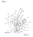
- Fig. 1 is a perspective view of a suspension apparatus as an embodiment of the present invention.
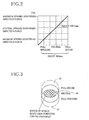
- Fig. 2 is a graph showing one of various conditions that are desirable to be met by the suspension apparatus.
- Fig. 3 is a view showing another condition that is desirable to be met by the suspension apparatus.
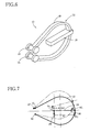
- Fig. 4 is a view showing another condition that is desirable to be met by the suspension apparatus.
- Fig. 5 is a view showing another condition that is desirable to be met by the suspension apparatus.
- Fig. 6 is a perspective view of a main suspension member of another suspension apparatus as another embodiment of the present invention.
- Fig. 7 is a view for explaining one measure to meet conditions that are required to be met by a main suspension member of the suspension apparatus of Fig. 1 .
- Fig. 8 is a view for explaining another measure to meet the conditions that are required to be met by the main suspension member of the suspension apparatus of Fig. 1 .
- Fig. 9 is a side view of the main suspension member shown in Fig. 8 .
- Fig. 10 is a view for explaining an operation of the main suspension member shown in Fig. 8 .
- Fig. 11 is a plan view for explaining a change of alignment associated with the main suspension member shown in Fig. 8 .
- Fig. 12 is a rear view for explaining the change of alignment associated with the main suspension member shown in Fig. 8 .
- Fig. 13 is a plan view for explaining a deformation of a main suspension member of another suspension apparatus as another embodiment of the present invention when a lateral-direction force is exerted to the suspension apparatus.
- Fig. 14 is a view for explaining an operation of the suspension apparatus of Fig. 13 .
- Fig. 15 is a view for explaining the operation of the suspension apparatus of Fig. 13 .
- Fig. 16 is a plan view for explaining a deformation of a main suspension member of another suspension apparatus as another embodiment of the present invention when a lateral-direction force and a front-rear-direction force are exerted to the suspension apparatus.
- Fig. 17 is a plan view for explaining an angle of inclination of a main suspension member of another suspension apparatus, as another embodiment of the present invention, that is defined relative to a front-rear direction of a vehicle's body.
- Fig. 18 is a rear view of another suspension apparatus as another embodiment of the present invention.
- Fig. 19 is a rear view for explaining an angle of inclination of a main suspension member of another suspension apparatus, as another embodiment of the present invention, that is defined relative to an upward-downward direction of a vehicle's body.
- Fig. 20 is a view for explaining an operation of the suspension apparatus of Fig. 18 .
- Fig. 21 is a view for explaining the operation of the suspension apparatus of Fig. 18 .
- Fig. 22 is a view for explaining the operation of the suspension apparatus of Fig. 18 .
- Fig. 23 is a plan view of a main suspension member of another suspension apparatus as another embodiment of the present invention.
- Fig. 24A is a side view showing another suspension apparatus as another embodiment of the present invention in a state in which a wheel is at a neutral position.
- Fig. 24B is a side view showing the suspension apparatus of Fig. 24A in a state in which the wheel is bounded.
- Fig. 25 is a perspective view showing an arrangement in which the suspension apparatus of Fig. 1 and a drive device are provided.
- Fig. 26 is a perspective view of the arrangement shown in Fig. 26 , taken in a different direction.
- Fig. 27 is a perspective view showing an arrangement in which the suspension apparatus of Fig. 1 and another drive device are provided.
- Fig. 28 is a perspective view of the arrangement shown in Fig. 27 , taken in a different direction.
- Fig. 29 is a perspective view showing an arrangement in which the suspension apparatus of Fig. 1 and another drive device are provided.
- Fig. 30 is a perspective view of an arrangement in which the suspension apparatus and the drive device, each shown in Figs. 25 and 26 , and a brake device are provided.
- Fig. 31 is a perspective view of an arrangement in which the suspension apparatus and the drive device, each shown in Figs. 27 and 28 , and a brake device are provided.
- Fig. 32 is a cross-section view taken along arrows 32, 32 shown in Fig. 31 .
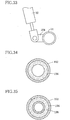
- Fig. 33 is a side view of a portion of another suspension apparatus as another embodiment of the present invention.
- Fig. 34 is a transverse cross-section view of a portion of another suspension apparatus as another embodiment of the present invention.
- Fig. 35 is a transverse cross-section view of a portion of another suspension apparatus as another embodiment of the present invention.
- Fig. 1 illustratively shows a rear-wheel suspension apparatus for a four-wheel automotive vehicle, to which the present invention is applied. More specifically explained, Fig. 1 is a view of a right-rear-wheel suspension apparatus, taken in an obliquely downward direction from a right-hand front side thereof. Hereinafter, the rear-wheel suspension apparatus will be referred to as just the suspension apparatus.
- the suspension apparatus includes, as a main constitutional element thereof, a main suspension member 10.
- the main suspension member 10 includes a main portion 12 constituted by an elongate pipe as an elongate material that is formed of a spring steel; a first and a second body-side attachment portion 14, 16 that are fixed to opposite ends of the main portion 12, respectively, and are each constituted by a hollow cylindrical material; and a wheel-side attachment portion 18 that is fixed to a portion of the main portion 12 that is the most distant from the body-side attachment portions 14, 16, more strictly, the most rear portion of the main portion 12 or the vicinity of the most rear portion.
- the main portion 12 is so formed as to have such a shape that the opposite ends of the elongate pipe are made near to each other, i.e., have a generally C-shaped configuration as seen in a lateral direction thereof.
- Each of the two body-side attachment portions 14, 16 is fixed to a corresponding one of the opposite end portions of the main portion 12 such that the each attachment portion 14, 16 intersects the corresponding end portion at a right angle or an angle near the right angle.
- the two body-side attachment portions 14, 16 are attached to a body of the vehicle, more specifically described, two brackets 22, 24 each as a portion of the vehicle's body, such that the two body-side attachment portions 14, 16 are pivotable about respective pivotal axes.
- each body-side attachment portion 14, 16 and the corresponding bracket 22, 24 there are provided a rubber bushing and an attachment axis member, each not shown.
- the rubber bushing includes an inner sleeve and an outer sleeve each of which is provided by a hollow cylindrical member, and additionally includes a rubber layer provided in a space present between the inner and outer sleeves. Owing to an elastic deformation of the rubber layer, transmission of vibration from each body-side attachment portion 14, 16 to the corresponding bracket 22, 24 can be effectively restrained.
- each body-side attachment portion 14, 16 can be pivoted relative to the corresponding bracket 22, 24.
- the main suspension member 10 is attached to the vehicle's body such that the two body-side attachment portions 14, 16 are pivotable about the respective pivotal axes thereof that coincide with respective centerlines thereof.
- the rubber bushing may be replaced with a ball bearing or a slide bearing.
- an elastic member such as a rubber sheet be provided between each bracket 22, 24 and the vehicle's body so as to restrain the transmission of vibration.
- the wheel-side attachment portion 18 is attached to a wheel holding member, not shown, that holds a wheel 30 such that the wheel 30 is rotatable.
- the main suspension member 10 defines a position of the wheel 30 relative to the vehicle's body, and allows, owing to an elastic deformation of the main portion 12 thereof, the wheel 30 to move relative to the body.
- a shock absorber 32 is provided between the wheel-side attachment portion 18 and the vehicle's body.
- a suspension device is required to have three main functions, i.e., a suspension-spring function, a suspension-link function, and a vibration damping function.
- the main suspension member 10 has the suspension-spring function, i.e., the function of causing the wheel 30 to support the vehicle's body while allowing the wheel 30 to move relative to the body in an upward-downward direction, and additionally has the suspension-link function, i.e., the function of defming the position of the wheel 30 relative to the vehicle's body.
- the main suspension member 10 is required to meet various conditions, i.e., have specific suspension characteristics, which will be described later.
- a considerable portion of the present suspension apparatus is provided in an inner space of the wheel 30, i.e., a space surrounded by a wheel disc and a rim of a wheel frame 36 that holds a tire 34 of the wheel 30. More specifically described, an entirety of the main suspension member 10 is located inside an inner circumferential surface of the wheel frame 36 as seen in an axial direction of the wheel 30, i.e., a lateral direction of the vehicle's body. In addition, not less than 90 % of the body-side attachment portion 14, not less than 80 % of the wheel-side attachment portion 18, and not less than 50 % of a neutral axis of the main portion 12 are located in the inner space of the wheel 30 as seen in a direction perpendicular to the axial direction of the wheel 30.
- reference numeral 38 designates a wheel-substitute member as a virtual member that virtually substitutes the wheel 30 so as to take, into account, an upward-downward-direction force F1, a lateral-direction force F2 and a front-rear-direction force F3 that are exerted from the wheel 30 to the wheel-side attachment portion 18.
- main suspension member 10 is required to have are as follows:
- an external force such as a front-rear-direction force or a lateral-direction force is exerted from the road surface to the wheel 30, it is desirable that an appropriate change of the alignment occur.
- a lateral-direction force is exerted inward of the vehicle, it is desirable that the toe angle change inward, i.e., toe-in occur.
- a suspension apparatus having desirable suspension characteristics can be obtained by employing one or more of those measures.
- the main portion 12 allows an upward-downward-direction stroke of the wheel 30.
- the length of the neutral axis of the main portion 12 increases, the elastic-deformation capability of the main portion 12 increases.
- the size of the suspension apparatus can be reduced by decreasing the length of the neutral axis.
- the length of the neutral axis should be selected at an appropriate value.
- the main portion 12 allows the upward-downward-direction stroke of the wheel 30.
- the shape and size of the transverse cross section of the main portion 12 largely influence the elastic-deformation capability and a maximum stress thereof.
- the main portion 12 is formed of an elongate pipe having an annular transverse cross section that is suitable for both bending and twisting, and allows easy calculations of respective amounts of deformation and stress.
- the main portion 12 may be formed of a different elongate material having a different transverse cross section, e.g., a band plate 48 having a rectangular transverse cross section as shown in Fig. 6 .
- the main portion 12 may be one whose cross-sectional shape and size are constant over its lengthwise entirety. However, for the purpose of averaging the stress and/or decreasing the overall weight, it is possible to vary at least one of the cross-sectional shape and size of the main portion 12 along its neutral axis. In the latter case, it is possible to vary, stepwise or continuously, at least one of the cross-sectional shape and size.
- the main suspension member 10 is just pivoted about the respective pivotal axes of the body-side attachment portions 14, 16, i.e., is not elastically deformed, when the upward-downward-direction force is exerted upward from the wheel 30 to the main suspension member 10. Thus, no elastic forces for the wheel 30 to support the vehicle's body are produced.
- Fig. 7 conceptually shows the main suspension member 10 shown in Fig. 1 .
- a point 52 representing the second body-side attachment portion 16 should be moved to a point 52' along an arc whose center rides on the point 50.
- the main portion 12 is elastically deformed.
- the two points 50, 52 i.e., the respective positions of the respective pivotal axes of the two body-side attachment portions 14, 16 are offset from each other in the upward-downward direction of the vehicle's body.
- the pivotal movement of the main suspension member 10 involves the elastic deformation of the main portion 12.
- the upward-downward-direction force F1 exerted from the wheel 30 to the main suspension member 10 is inputted to an input point 54 of the wheel-side attachment portion 18 and, because of a distance present between the input point 54 and an input point 56 of the main portion 12 (hereinafter, referred to as the "first arm length A1"), the input point 56 of the main portion 12 receives the upward-directed, upward-downward-direction force F1, and an angular moment M1 that is clockwise in Fig. 7 (i.e., a product of the upward-downward-direction force F1 and the first arm length A1). Therefore, the main portion 12 produces not only an elastic force to return the point 52' to the point 52 but also an elastic force based on the angular moment M1.
- the two body-side attachment portions 14, 16 may interfere with each other, or one of the two body-side attachment portions 14, 16 may interfere with the main portion 12, if the amount of offsetting of the two attachment portions 14, 16 is too small.
- the two body-side attachment portions 14, 16 may not be offset from each other by a desirable amount.
- the two body-side attachment portions 14, 16 are offset from each other in the direction parallel to the respective pivotal axes thereof, the above-described interference can be avoided, and the two attachment portions 14, 16 can be offset from each other by a desirable amount even if the desirable amount may be very small.
- the advantage that the interference of the two body-side attachment portions 14, 16 with each other or the interference of one of the two body-side attachment portions 14, 16 with the main portion 12 can be avoided, can be found in a case, described later, where the respective pivotal axes of the two body-side attachment portions 14, 16 are inclined relative to each other.
- the main suspension member 10 can more easily resist an angular moment to pivot the suspension member 10, in its plan view, about the respective opposite ends thereof located on the side of the two body-side attachment portions 14, 16, as compared with the case where the two body-side attachment portions 14, 16 are not offset from each other in the direction parallel to the respective pivotal axes thereof.
- the shape of the main portion 12 can be selected from a wider range as compared with the case where the two body-side attachment portions 14, 16 are not offset from each other in the direction parallel to the respective pivotal axes thereof. This contributes to increasing the degree of freedom of designing of the present suspension apparatus.
- the main portion 12 can be elastically deformed when the main suspension member 10 is pivoted.
- reference numeral 61 designates a most rear point of the main portion 12
- reference numeral 62 designates an upper portion of the main portion 12 that is located on an upper side of the most rear point 61
- reference numeral 64 designates a lower portion of the main portion 12 that is located on a lower side of the most rear point 61.
- the upper portion 62 is drawn by a solid line; and the lower portion 64 is drawn by a broken line.
- the middle point of the pivotal axis of each body-side attachment portion 14, 16 is defined as an intersection point where the pivotal axis intersects a middle plane of the each body-side attachment portion 14, 16 with respect to the axial direction thereof.
- the middle point coincides with an intersection point where the pivotal axis of each body-side attachment portion 14, 16 intersects the neutral axis of the main portion 12.
- the pivotal axis of the first body-side attachment portion 14 is not moved and the middle point 60 of the second body-side attachment portion 16 is not moved, either.
- the pivotal axis of the second body-side attachment portion 16 is revolved about the straight line L1.
- the pivotal axis of the second body-side attachment portion 16 constitutes a generator 74 of a conical surface 72.
- the main portion 12 is mainly subjected to a twisting elastic deformation; and owing to the rotation by the angle ⁇ , the main portion 12 is mainly subjected to a bending elastic deformation.
- the main portion 12 Since the angle ⁇ is greater than the angle ⁇ , the main portion 12 is mainly subjected to the twisting elastic deformation (and also to a bending elastic deformation caused by a twisting moment, as described later), and this elastic deformation produces an elastic force for the wheel 30 to support the vehicle's body.
- the middle point of the pivotal axis of one of the two attachment portions 14, 16 is offset from the pivotal axis of the other attachment portion 14, 16 and, in a particular case, the middle point of the pivotal axis of each one of the two attachment portions 14, 16 is offset from the pivotal axis of the other attachment portion 14, 16.
- the main portion 12 can produce, as the suspension member 10 is pivoted about the straight line, an elastic force for the wheel 30 to support elastically the vehicle's body.
- the respective middle points of the respective pivotal axes of the first and second attachment portions 14, 16 are offset from the respective pivotal axes of the second and first attachment portions 16, 14.
- the main portion 12 can be elastically deformed as the suspension member 10 is pivoted. If, additionally, the middle point of the pivotal axis of the second body-side attachment portion 16 is offset from the pivotal axis of the first body-side attachment portion 14 in the direction perpendicular to the latter pivotal axis, the main portion 12 can be elastically deformed for the same reason as explained above with respect to Item (iii). Thus, in the latter case, the measures described at Item (v) and the measures described at Item (iii) are combined with each other.
- the elastic-deformation capability of the main suspension member 10 can be changed by selecting the length of the neutral axis of the main portion 12.
- a maximum value of the upward-downward-direction stroke of the wheel 30, a wheel rate of the wheel 30, or a change of alignment of the wheel 30 that corresponds to the upward-downward-direction stroke thereof can be adjusted as desired, by (A) selecting an appropriate shape of the main portion 12 [e.g., selecting a shape of curvature of the main portion 12 (in particular, a shape of curvature of the main portion 12 as a whole in its side view), or selecting respective proportions of respective lengths of respective neutral axes of (a) a first portion of the main portion 12 located between the first body-side attachment portion 14 and the wheel-side attachment portion 18 and (b) a second portion of the main portion 12 located between the second body-side attachment portion 16 and the wheel-side attachment portion 18], (B) selecting an angle of inclination of the pivotal axis of the second body-side attachment portion 16 relative
- the change of alignment of the wheel 30 can be adjusted by combining, with each other, the measures, described at Item (v), that the respective pivotal axes of the two body-side attachment portions 14, 16 are inclined relative to each other and the measures, described at Item (vi), that the shape of the main suspension member 10 is selected, in the following manner:
- the pivotal axis of the first body-side attachment portion 14 is parallel to the lateral direction of the vehicle's body, and the pivotal axis of the second body-side attachment portion 16 is inclined on a horizontal plane such that the pivotal axis goes frontward as it goes outward.
- the wheel-side attachment portion 18 is moved counterclockwise in Fig. 12 , owing to an angular moment M2 equal to the product of the second arm length A2 and the upward-downward-direction force F1. For this reason, too, the camber angle of the wheel 30 is changed toward the negative side.
- the first amount of change of the camber angle based on the twisting elastic deformation of the main portion 12 increases as the angle of inclination of the pivotal axis of the second body-side attachment portion 16 increases; and the second amount of change of the camber angle based on the angular moment M2 increases as the second arm length A2 increases.
- each of the first and second amounts increases as the upward-directed, upward-downward-direction force F1 exerted to the wheel 30 increases, i.e., as the upward-downward-direction stroke of the wheel 30 in the bound direction increases.
- the amount of change of the toe angle increases as the angle of inclination of the pivotal axis of the second body-side attachment portion 16 increases; and the amount of change of the toe angle increases as the upward-directed, upward-downward-direction force F1 exerted to the wheel 30 increases, i.e., as the upward-downward-direction stroke of the wheel 30 in the bound direction increases.
- the wheel-side attachment portion 18 is provided at the most distant portion (i.e., the most rear point 61 or its vicinity) of the main portion 12 from the two body-side attachment portions 14, 16.
- the most distant portion i.e., the most rear point 61 or its vicinity
- the input position where the force is inputted from the wheel 30 to the wheel-side attachment portion 18 can be largely changed.
- the magnitude of the angular moment M2 exerted to the main portion 12 based on the upward-directed, upward-downward-direction force F1 that is exerted from the wheel 30 to the wheel-side attachment portion 18, can be changed depending upon the second arm length A2.
- a magnitude of an angular moment M3 exerted to the main portion 12 based on the lateral-direction force F2 that is exerted from the road surface to the wheel-side attachment portion 18, can be changed depending upon the first arm length A1.
- the angular moment M3 based on the lateral-direction force F2 operates as a moment to twist the main portion 12. More specifically explained, as conceptually shown in Fig.
- the main portion 12 since, owing to the lateral- direction force F2, the main portion 12 is subjected to a bending elastic deformation, there arises a tendency that the wheel-side attachment portion 18 is moved clockwise in its plan view; and since owing to the angular moment M3 the main portion 12 is subjected to a twisting elastic deformation, there arises a tendency that the wheel-side attachment portion 18 is moved counterclockwise in its plan view.
- the wheel-side attachment portion 18 is subjected to a displacement (i.e., a rotation) as a sum of the two tendencies.
- the wheel-side attachment portion 18 is subjected to just a translation in the lateral direction; if the tendency of rotation based on the bending elastic deformation is stronger, the wheel-side attachment portion 18 is subjected to a clockwise rotation, so that the wheel 30 is moved toward the toe-out side ( Fig. 5 ); and if the tendency of rotation based on the twisting elastic deformation is stronger, the wheel-side attachment portion 18 is subjected to a counterclockwise rotation, so that the wheel 30 is moved toward the toe-in side.
- the lateral- direction force F2 may be said as operating on an elastic main axis of the main suspension member 10.
- a main portion 12 has a C-shaped profile defined by an arc and two tangential lines thereof, an clastic main axis with respect to a lateral force is located in a hatched area in the vicinity of the center of the arc.
- the elastic main axis is located at a point 76 and the lateral-direction force F2 is exerted to a point 78 (i.e., a centerline of an axle shaft of the wheel 30 passes through the point 78), the wheel 30 has a tendency to move toward the toe-in side. That is, if the centerline of the shaft of the wheel 30 is located in front of the elastic main axis, then the wheel 30 has the tendency toward the toe-in side; and if the centerline of the shaft of the wheel 30 is located in rear of the elastic main axis, then the wheel 30 has the tendency toward the toe-out side.
- the tendency toward the toe-in or toe-out side increases as the distance of the centerline of the shaft of the wheel 30 from the elastic main axis increases.
- the change of the toe angle based on the lateral-direction force F2 can be arbitrarily modified by selecting the first arm length A1 (i.e., selecting the position of the shaft of the wheel 30).
- Item (vii) has been explained with respect to the embodiment where the main portion 12 extends parallel to the front-rear direction of the vehicle's body. However, as shown in Fig. 16 , it is possible to incline the main portion 12 relative to the front-rear direction of the vehicle's body in its plan view. In this case, the change of the toe angle can be modified based on not only the lateral-direction force F2 but also the front-rear-direction force F3.
- Respective proportions of the change of the toe angle based on the lateral-direction force F2 and the change of the toe angle based on the front-rear-direction force F3 can be changed by changing an angle of inclination of the main portion 12 relative to the front-rear direction of the vehicle's body.
- the respective pivotal axes of the two body-side attachment portions 14, 16 are parallel to each other, are offset from each other in the upward-downward direction of the vehicle's body, and are inclined relative to the lateral direction of the body.
- these features are not essentially required.
- the two body-side attachment portions 14, 16 are not offset from each other in a direction parallel to the respective pivotal axes thereof, and the neutral axis of the main portion 12 is located on a single plane perpendicular to those pivotal axes.
- an angle of inclination of the main suspension member 10 relative to the front-rear direction of the vehicle's body is simply equal to an angle of inclination of the above-indicated single plane relative to the front-rear direction.
- the neutral axis of the main portion 12 is not located on a single plane. In this case, an angle of inclination of the main suspension member 10 cannot be univocally determined.
- a reference plane 98 is conveniently defined as a vertical plane that passes through (a) a middle point 94 between a first intersection point 90 and a second intersection point 92 where respective pivotal axes 80, 82 of the two body-side attachment portions 14, 16 intersect two extension lines 84, 86 that are extended from opposite ends of the neutral axis of the main portion 12 and (b) a most distant point 96 on the neutral axis that is the most distant from the middle point 94, and an angle of inclination of the reference plane 98 relative to the front-rear direction of the vehicle's body is defined as the angle of inclination of the main suspension member 10 relative to the front-rear direction.
- first intersection point 90 is regarded as representing the first body-side attachment portion 14; and the second intersection point 92 is regarded as representing the second body-side attachment portion 16.
- a relative position between the main portion 12 and the two body-side attachments portions 14, 16 may not be so determined that the respective points representing the two body-side attachment portions 14, 16 coincide with the respective middle points of those portions 14, 16 with respect to the respective axial directions thereof. That is, depending upon the circumstances, the respective axial-direction middle points of the two body-side attachment portions 14, 16 may be intentionally offset from the respective points representing the two attachment portions 14, 16. In the last case, the respective axial-direction middle points of the two body-side attachment portions 14, 16 may be newly defined as the respective points representing the two attachment portions 14, 16.
- the reference plane 98 of the main suspension member 10 is defined as explained above. Using this definition of the reference plane 98, the angle of inclination of the main suspension member 10 relative to the front-rear direction can be discussed irrespective of which shape the member 10 may have.
- the respective pivotal axes of the two body-side attachment portions 14, 16 are parallel to each other, and accordingly it is generally said to be reasonable to assume that the main suspension member 10 is pivoted along a plane that perpendicularly intersects those pivotal axes.
- the virtual straight line may not accurately coincide with an actual pivotal axis of the main suspension member 10, because of the shape of the main portion 12, in particular, a difference of respective lengths of respective neutral axes, or a difference of respective curved shapes, of (a) the first portion of the main portion 12 located between the body-side attachment portions 14 and the wheel-side attachment portion 18 and (b) the second portion of the main portion 12 located between the body-side attachment portions 16 and the wheel-side attachment portion 18.
- an amount of deviation of the virtual straight line i.e., the virtual pivotal axis
- the main suspension member 10 is pivoted about the virtual pivotal axis. That is, the embodiment shown in Fig. 16 meets both the condition described at Item (viii) and the condition described at Item (ix).
- the toe angle, or the camber angle, of the wheel 30 held by the main suspension member 10 is changed with the upward-downward- direction stroke of the wheel 30, like a toe angle, or a camber angle, of a wheel held by a conventional semi-trailing-arm-type suspension device.
- inclining the virtual pivotal plane relative to the front-rear direction of the vehicle's body can be utilized as means for adjusting the alignment of the wheel 30.
- a virtual pivotal axis and/or a virtual pivotal plane of the main suspension member 10 cannot be easily determined or defined.
- a virtual pivotal axis 100 and a virtual pivotal plane 101 are determined or defined as follows: First, a first intersection point 90 and a second intersection point 92 where the respective pivotal axes 80, 82 of the two body-side attachment portions 14, 16 respectively intersect two extension lines 84, 86 that are respectively extended from opposite ends of the neutral axis of the main portion 12, are determined; then a middle point 94 of the first and second intersection points 90, 92 that is located on a straight line passing through the points 90, 92, is determined; and a straight line that passes through the middle point 94 and extends in a direction as an average of respective directions in which the two pivotal axes 80, 82 extend, is determined as the virtual pivotal axis 100, and a plane that perpendicularly intersects the virtual pivotal axis 100, is determined as the virtual pivotal plane 101.
- the virtual pivotal axis 100 is defined by a bisector (i.e., a straight line) that passes through the middle point 94 and extends in a direction that equally divides an angle contained by the two pivotal axes 80, 82. Since the virtual pivotal axis 100 is inclined relative to the lateral direction of the vehicle's body, the main suspension member 10 can enjoy the advantages described at Item (ix).
- inclining the main suspension member 10 relative to the front-rear direction of the vehicle's body it is possible to incline the main suspension member 10 relative to the upward-downward direction of the vehicle's body.
- the main member 10 may be provided in an inner space of the wheel 30, or a drive device and/or a brake device can be easily provided in the vicinity of the main member 10.
- Fig. 18 shows a main suspension member 10 that is inclined relative to only the upward-downward direction of the vehicle's body.
- an angle of inclination of the main suspension member 10 relative to the upward-downward direction of the vehicle's body is determined as follows: Regarding, e.g., an embodiment shown in Fig.
- first, a first intersection point 90 and a second intersection point 92 where the respective pivotal axes of the two body-side attachment portions 14, 16 respectively intersect two extension lines that are respectively extended from opposite ends of the neutral axis of the main portion 12, are determined; then a middle point 94 between the first and second intersection points 90, 92 that is located on a straight line passing through the two points 90, 92, is determined; a plane that contains the middle point 94, and an uppermost point 102, and a lowermost point 104, of the neutral axis of the main portion 12, is determined as a reference plane 106; and an angle of inclination of the reference plane 106 relative to the upward-downward direction of the vehicle's body is determined as the angle of inclination of the main suspension member 10 relative to the upward-downward direction.
- the main suspension member 10 is inclined relative to not only the upward-downward direction of the vehicle's body but also the front-rear direction thereof.
- the reference plane of the main suspension member 10 is defined by two methods, i.e., the method described with respect to Item (viii) and the method described with respect to the present item, i.e., Item (x), then two reference planes can be obtained for the single main suspension member 10.
- the main suspension member 10 may have two inclination angles each relative to the upward-downward direction of the vehicle's body, and two inclination angles each relative to the front-rear direction thereof.
- the main suspension member 10 has a single reference plane, and that respective inclination angles of the single reference plane relative to the upward-downward and front-rear directions of the vehicle's body are respective inclination angles of the main suspension member 10 relative to the upward-downward and front-rear directions.
- the above-described reference plane 106 that contains the middle point 94 and the uppermost and lowermost points 102, 104 is the only reference plane of the main suspension member 10.
- the main suspension member 10 is inclined relative to the upward-downward direction of the vehicle's body, and the virtual pivotal plane of the main suspension member 10 is also inclined relative to the upward-downward direction. If the virtual pivotal plane of the main suspension member 10 is inclined relative to the upward-downward direction, and an inclination angle of the virtual pivotal plane is adjusted, then respective directions in which the main member 10 can be easily elastically deformed and cannot be easily elastically deformed can be adjusted with respect to respective angles thereof relative to the upward-downward direction of the vehicle's body or the lateral direction thereof. Thus, for example, a roll center of the vehicle's body can be easily adjusted.
- this feature will be described in more detail.
- a conventional suspension device as a whole can be modeled by being substituted by a link 112 that is not easily elastically deformed (i.e., has a high rigidity) and is pivotable about a pivotal axis 110, and a spring 114 that is easily elastically deformed when the link 112 is pivoted (i.e., has a low rigidity). If the thus modeled suspension device receives the lateral-direction force F2 from the wheel 30, then the link 112 and the spring 114 receive, by sharing, the lateral-direction force F2.
- a component received by the link 112 will be referred to as the link-shared component F2a; and a component received by the spring 114 will be referred to as the spring-shared component F2b. Since the rigidity of the link 112 is high, a displacement of the wheel 30 due to the link-shared component F2a is small; and since the rigidity of the spring 114 is low, a displacement of the wheel 30 due to the spring-shared component F2b is large. Thus, a direction in which the wheel 30 can be easily displaced (or cannot be easily displaced) can be changed by changing the inclination angle of the link 112 relative to the upward-downward, or lateral, direction of the vehicle's body.
- the suspension apparatus shown in Fig. 18 , has a direction in which the apparatus exhibits a high rigidity, and a direction in which the apparatus exhibits a low rigidity.
- the main portion 12 is easily elastically deformed in the first direction perpendicular to the respective pivotal axes of the two body-side attachment portions 14, 16, but is not easily elastically deformed in the second direction parallel to those pivotal axes.
- the main portion 12 functions as a spring; and for a force exerted thereto in the second direction, the main portion 12 functions as a link. Therefore, as shown in Fig.
- the link-shared component F2a and the spring-shared component F2b have respective directions indicated in the figure.
- the link-shared component F2a and the spring-shared component F2b have been replaced with each other.
- the suspension apparatus shown in Fig. 21 has a direction in which the apparatus exhibits a high rigidity, and a direction in which the apparatus exhibits a low rigidity.
- the suspension apparatus shown in Fig. 21 can be utilized to adjust the roll center of the vehicle's body.
- Fig. 22 shows the vehicle in a state in which it is turning rightward.
- an angular moment based on an inertia force exerted to a gravity center 120 of a vehicle's body 118 is received by a road surface via left and right wheels 30.
- the left and right wheels 30 are revolved relative to the body 118, owing to the respective suspension apparatuses 10, about respective instantaneous centers 122, 124 each of which is defined by respective directions of the link-shared component F2a and the spring-shared component F2b.
- a position of the roll center 126 of the body 118 can be adjusted by adjusting the respective directions of the link-shared component F2a and the spring-shared component F2b received by each of the main suspension members 10, in other words, the direction of the virtual pivotal plane of each of the main suspension members 10 as seen in a view taken in the front-rear direction of the body 118.
- the two body-side attachment portions 14, 16 are attached to the two brackets 22, 24, respectively, such that each of the two attachment portions 14, 16 is not movable in the axial direction thereof.
- the first body-side attachment portion 14 is not movable in its axial direction but the second body-side attachment portion 16 is movable in its axial direction.
- This embodiment employs a pair of elastic members 130 that produce, as the body-side attachment portion 16 is moved in its axial direction, an elastic force to return the attachment portion 16 to its initial position.
- the elastic deformation (in particular, twisting elastic deformation) of the main portion 12 is easier, and the elastic-deformation capability of the main suspension member 10 is higher.
- the respective pivotal axes of the two body-side attachment portions 14, 16 are inclined relative to each other by a sufficiently large angle. In this case, it is possible that both the two body-side attachment portions 14, 16 be freely movable in the respective axial directions thereof, because the position of the main suspension member 10 in the lateral direction of the vehicle's body is univocally determined. However, in the case where the respective pivotal axes of the two attachment portions 14, 16 are inclined relative to each other by only a small angle, or in the case where the two pivotal axes are parallel to each other, it is preferred that one of the two attachment portions 14, 16 be not movable in its axial direction or be less movable than the other of the two portions 14, 16.
- a main suspension member 10 having desired suspension characteristics it is possible to employ a main suspension member 10 having desired suspension characteristics, by combining two or more of the above-described measures or conditions described at Items (i) through (xi). To this end, it is preferred to calculate, using a finite element method or the like, a strain, a stress and/or a displacement of each portion of the main suspension member 10. However, this calculation is not essentially required. For example, it is possible to produce a prototype, perform an experiment to measure the behavior of the prototype, and improve the prototype so as to have desired suspension characteristics.
- Figs. 24A and 24B show another embodiment.
- the main suspension member 10 is provided with an auxiliary spring 140.
- the auxiliary spring 140 is provided between two spring holding portions 142, 144 a distance of which is changed as the two attachment portions 14, 16 are pivoted.
- the two spring-holding portions 142, 144 are provided by two spring-holding pins that radially outward project from respective specific portions of the two attachment portions 14, 16 a distance of which increases as the two attachment portions 14, 16 are pivoted.
- the auxiliary spring 140 is provided by a tensile coil spring located between the two spring holding pins 142, 144.
- the auxiliary spring 140 is stretched or extended and accordingly the elastic-deformation capability of the main suspension member 10 is lowered as such. This is equivalent to the increase of spring constant of the suspension member 10. Therefore, if the auxiliary spring 140 is attached to, or detached from, the suspension member 10, or if one auxiliary spring 140 is replaced with another auxiliary spring 140 having a different spring constant than that of the one spring 140, the spring constant of the suspension member 10 can be changed to each of a plurality of steps.
- This embodiment can be utilized for a case where a single type of automotive cars is modified to have different overall weights. For example, if the auxiliary spring 140 is attached to, or detached from, the main suspension member 10, those automotive cars that have the different overall weights can be adjusted to take a same body's height or level when each car is in its neutral state.
- this embodiment can be utilized for another case where an identical suspension device is commonly employed by different types of automotive cars. In the latter case, those automotive cars can take respective desired body's height or levels when each car is in its neutral state.
- a suspension apparatus in accordance with the present invention can enjoy a simple construction and accordingly a drive device and/or a brake device for the wheel 30 can be easily provided in an inner space of the wheel frame 36.
- Figs. 25 through 29 show some embodiments in which a drive device is provided. More specifically explained, Figs. 25 and 26 show an embodiment in which a drive source of the drive device is provided outside the inner space of the wheel frame 36 and the wheel 30 is driven by the drive source via a drive shaft 150 extending through the wheel-side attachment portion 18.
- Figs. 27 and 28 show an embodiment in which an entirety of a drive device including an electric motor 152 as its drive source is provided in the inner space of the wheel frame 36.
- the electric motor 152 is an inner-rotor-type electric motor whose rotary torque is transmitted to the wheel frame 36 via a reduction-gear unit 154.
- the electric motor 152 and the reduction-gear unit 154 are attached to the wheel-side attachment portion 18, such that generally, the motor 152 and the reduction-gear unit 154 are provided between the upper portion 62 of the main portion 12 and the wheel disc of the wheel frame 36.
- Fig. 29 shows an embodiment in which a drive device including an outer-rotor-type electric motor 162 as its drive source, is provided in the inner space of the wheel frame 36.
- An outer rotor 164 is fixed to an inner circumferential surface of the wheel frame 36, and an inner stator 166 is fixed to the wheel-side attachment portion 18.
- Figs. 30 through 32 show embodiments in which a drive device and a brake device are provided in the inner space of the wheel frame 36. More specifically explained, Fig. 30 shows an embodiment in which the drive device, shown in Figs. 25 and 26 , that drives the wheel frame 36 via the drive shaft 150 is provided in combination with a disc brake 170 as the brake device.
- the disc brake 170 includes a disc rotor 172 fixed to the wheel frame 36, and a caliper 174 attached to the wheel-side attachment portion 18.
- the caliper 174 has a wheel cylinder 176 that is hydraulically operable to press a brake pad against the disc rotor 172 in an axial direction of the wheel frame 36 and thereby restrain the rotation of the rotor 172.
- the brake pad is movable in a direction parallel to the axial direction of the wheel frame 36.
- Figs. 31 and 32 show an embodiment in which the drive device, shown in Figs. 27 and 28 , that includes the inner-rotor-type electric motor 152 and the reduction-gear unit 154 is provided in combination with the above-described disc brake 170.
- the disc rotor 172 is of a hat type including an annular friction-plate portion 180 and a bottomed cylindrical portion 182.
- the electric motor 152 is provided adjacent to the friction-plate portion 180, as seen in the axial direction of the wheel frame 36, and a portion of the reduction-gear unit 154 is provided in an inner space of the cylindrical portion 182.
- the caliper 174 is provided such that the wheel cylinder 176 thereof is located between (a) a specific portion of the main portion 12 that is adjacent to the body-side attachment portion 16 and (b) the disc rotor 172, and is attached to the wheel-side attachment portion 18 either directly, or indirectly via a casing of the reduction-gear unit 154.
- a flange portion projecting radially inward from the inner circumferential surface of the wheel rim may be utilized as the disc rotor.
- the caliper may be provided at a position that is arbitrarily selected in a space that is present between the main suspension member 10 and the wheel disc and that has a sufficiently large axial-direction size.
- the caliper may be provided in a space that is located inward of the attachment portion 14 with respect to the lateral direction of vehicle's body.
- the shock absorber 32 is provided between the wheel-side attachment portion 18 and the vehicle's body.
- a damping effect may be obtained in the case where the shock absorber 32 is provided between the vehicle's body and an arbitrary portion of the main portion 12. In this case, however, an elastic-deformation mode of the main portion 12 is changed by a force exerted thereto from the shock absorber 32, and it becomes difficult to obtain desired changes of alignment of the wheel 30.
- the shock absorber 32 is provided between the wheel-side attachment portion 18 and the vehicle's body, as described above, then the force exerted from the shock absorber 32 is just added to the force exerted from the wheel frame 36, and accordingly the elastic-deformation mode of the main portion 12 is less influenced or the influence, if any, can be easily taken into account. Thus, the desired changes of alignment of the wheel 30 can be easily obtained.
- the shock absorber 32 between the vehicle's body and at least one of the two body-side attachment portions 14, 16.
- an arm portion 184 is projected radially outward from either one, or each one, of the two body-side attachment portions 14, 16, and the shock absorber 32 is provided between the vehicle's body and a free end of the arm portion 184.
- the damping device constituted by the common shock absorber 32 in which the resistance to flows of fluid is utilized, it is possible to employ a solid-type damping device that damps vibration owing to a frictional force produced between solid members or an internal friction produced in a solid member.
- the solid-type damping device may be one including a damping material that is provided along the main portion 12 of the main suspension member 10 and that produces a damping force when the main portion 12 is elastically deformed.
- the main portion 12 is constituted by the single band plate 48
- the single band plate 48 may be replaced with a plurality of band plates that are superposed on each other and are elastically pressed on each other such that respective major surfaces of the band plates are held in close contact with each other.
- a damping material may be provided between the band plates such that the damping material exhibits a damping function.
- the damping device may be said as a stacked-plate-spring-type damping device that also functions as a suspension spring.
- a damping material be provided along an inner circumferential surface of the tubular member.
- an inner tube 196 is provided inside the inner layer 194.
- the outer tube 192 and the inner tube 196 are moved relative to each other and accordingly the inner layer 194 exhibits a damping effect to advantage.
- the suspension apparatus as a whole can be provided in a considerably small space.
- the elastic-deformation mode of the main portion may be changed by the damping force and desirable changes of alignment of the wheel 30 may not be obtained.
- the elastic-deformation mode of the main portion is not changed by the provision of the damping device, and accordingly the main suspension member 10 or the suspension apparatus including the same 10 can be designed with ease.
- the foregoing description relates to the suspension apparatus that is particularly suitable for use with each of the rear wheels of the four-wheel automotive vehicle.
- the present invention may be applicable to a suspension apparatus for use with each of the front wheels of the four-wheel automotive vehicle.
- each of the above-described embodiments relates to the suspension apparatus constituted by the main suspension member and the damping device. Since this suspension apparatus has the simplest construction, it can particularly effectively enjoy the advantages of the present invention. Though this suspension apparatus, constituted by the combination of the main suspension member and the damping device, can satisfactorily achieve the object of the present invention, it may additionally employ the above-described springs 130, or one or more auxiliary links, so as to obtain ideal changes of alignment of the wheel 30.
Landscapes
- Engineering & Computer Science (AREA)
- Mechanical Engineering (AREA)
- Vehicle Body Suspensions (AREA)
- Springs (AREA)
Claims (14)
- Aufhängungsvorrichtung für ein Fahrzeug mit einer Karosserie und einem Rad (30), die als ein Hauptelement derselben ein Hauptaufhängungsteil (10) aufweist, das sowohl als Aufhängungsfeder als auch als Aufhängungsverbindung wirkt, und (a) einen Hauptabschnitt (12), der aus einem länglichen Material so gebildet ist, dass entgegengesetzte Enden des Hauptabschnitts nahe beieinander liegen, (b) einen ersten karosserieseitigen Anbringabschnitt (14) und einen zweiten karosserieseitigen Anbringabschnitt (16), die jeweils an den entgegengesetzten Enden des Hauptabschnitts (12) vorgesehen sind und die an der Karosserie des Fahrzeugs so angebracht sind, dass der erste karosserieseitige Anbringabschnitt (14) und der zweite karosserieseitige Anbringabschnitt (16) um eine erste Schwenkachse (80) und eine zweite Schwenkachse (82) jeweils einzeln relativ zu der Karosserie schwenkbar sind, und (c) einen radseitigen Anbringabschnitt (18) umfasst, der an einem Abschnitt des Hauptabschnitts (12) vorgesehen ist, der von den ersten und zweiten karosserieseitigen Anbringabschnitten (14, 16) entfernt ist, und der an einem radseitigen Teil angebracht ist, das auf einer Seite des Rads (30) vorgesehen ist, wobei jeweilige Positionen der ersten und zweiten Schwenkachsen (80, 82) relativ zueinander so ausgewählt sind, dass die ersten und zweiten Schwenkachsen (80, 82) relativ zueinander geneigt sind und der Hauptabschnitt (12) elastisch verformt wird, wenn die ersten und zweiten karosserieseitigen Anbringabschnitte (14, 16) jeweils um die ersten und zweiten Schwenkachsen (80, 82) geschwenkt werden,
und wobei weiterhin
der radseitige Anbringabschnitt (18) an einem spezifischen Abschnitt (61) des Hauptabschnitts (12) befestigt ist, der von den ersten und zweiten karosserieseitigen Anbringabschnitten (14, 16) in einer Längsrichtung der Karosserie des Fahrzeugs am weitesten entfernt ist,
der Hauptabschnitt (12) in einer Querschnittsrichtung der Karosserie des Fahrzeugs einen im Allgemeinen C-förmigen Aufbau so aufweist, dass der Hauptabschnitt (12) einen oberen Abschnitt (62) aufweist, der oberhalb des radseitigen Anbringabschnitts (18) angeordnet ist, und einen unteren Abschnitt (64), der unterhalb des radseitigen Anbringabschnitts (18) angeordnet ist, und
wobei der Hauptabschnitt (12), der den unteren Abschnitt (64) umfasst, eine verdrehende elastische Verformung erfährt, wenn die ersten und zweiten karosserieseitigen Anbringabschnitte (14, 16) jeweils um die ersten und zweiten Schwenkachsen (80, 82) geschwenkt werden. - Aufhängungsvarrichtung nach Anspruch 1, wobei die ersten und zweiten karosserieseitigen Anbringabschnitte (14, 16) gegeneinander in einer Richtung versetzt sind, die eine Richtungskomponente senkrecht zu entweder der ersten oder zweiten Schwenkachse aufweist.
- Aufhängungsvorrichtung nach Anspruch 1 oder 2, wobei in einer Draufsicht die ersten und zweiten Schwenkachsen relativ zueinander geneigt sind.
- Aufhängungsvorrichtung nach Anspruch 1, 2 oder 3, wobei ein erster Schnittpunkt (90) und ein zweiter Schnittpunkt (92), an welchem die ersten und zweiten Schwenkachsen (80, 82) jeweils zwei Verlängerungslinien (84, 86) schneiden, die jeweils von entgegengesetzten Enden einer neutralen Achse des Hauptabschnitts (12) wegführen, jeweils nicht auf einer von der zweiten Schwenkachse (82) ausgehenden Verlängerungslinie und einer von der ersten Schwenkachse (80) ausgehenden Verlängerungsünie liegen.
- Aufhängungsvorrichtung nach Anspruch 1, 2, 3 oder 4, wobei eine relativ zu einer Längsrichtung der Karosserie des Fahrzeugs geneigte Referenzebene (98), die eine senkrechte Ebene ist, welche durch (a) einen Mittelpunkt (94) zwischen einem ersten Schnittpunkt (90) und einem zweiten Schnittpunkt (92) geht, an welchen die ersten und zweiten Schwenkachsen (80, 82) jeweils zwei Verlängerungslinien (84, 86) schneiden, die jeweils von entgegen gesetzten Enden einer neutralen Achse des Hauptabschnitts (12) wegführen, und (b) einen Punkt (96) auf der neutralen Achse geht, der sich in einer Draufsicht am weitesten entfernt von dem Mittelpunkt (94) befindet, ist.
- Aufhängungsvorrichtung nach einem der vorhergehenden Ansprüche, wobei eine gerade Linie (100), die durch einen Mittelpunkt (94) zwischen einem ersten Schnittpunkt (90) und einen zweiten Schnittpunkt (92) geht, an denen jeweils die ersten
und zweiten Schwenkachsen (80, 82) jeweils zwei Verlängerungslinien (84, 86) schneiden, die sich jeweils von entgegengesetzten Enden einer neutralen Achse des Hauptabschnitts (12) wegführen, und die sich in einer Richtung eines Mittels jeweiliger Richtungen erstreckt, in welcher sich die ersten und zweiten Schwenkachsen (80, 82) erstrecken, in einer in der Längsrichtung der Karosserie des Fahrzeugs aufgenommenen Ansicht gegenüber einer Querrichtung der Karosserie des Fahrzeugs geneigt ist. - Aufhängungsvorrichtung nach Anspruch 1, wobei die ersten und zweiten Schwenkachsen (80, 82) relativ zueinander auf einer gemeinsamen Ebene geneigt sind, und ein Schnittpunkt (92), an welchem eine (82) der ersten und zweiten Schwenkachsen (80, 82) eine Verlängerungslinie (86) schneidet, die sich von einem Ende einer neutralen Achse des Hauptabschnitts (12) erstreckt, auf einer Verlängerungslinie angeordnet ist, die von einer anderen (80) der ersten und zweiten Schwenkachsen wegführt.
- Aufhängungsvorrichtung nach einem der vorhergehenden Ansprüche, wobei der radseitige Anbringungsabschnitt (18) an einem spezifischen Abschnitt (61) des Hauptabschnitts befestigt ist, der von den ersten und zweiten karosserieseitigen Anbringabschnitten (14, 16) in der Längsrichtung der Karosserie des Fahrzeugs am weitesten entfernt ist, sich von dem spezifischen Abschnitt hin zu den ersten und zweiten karosserieseitigen Anbringabschnitten (14, 16) erstreckt, und an einem wegführenden Endabschnitt eine Querkraft aufnimmt, die von dem Rad (30) darauf ausgeübt wird.
- Aufhängungsvorrichtung nach einem der vorhergehenden Ansprüche, wobei die ersten und zweiten karosserieseitigen Anbringabschnitte (14, 16) an der Karosserie des Fahrzeugs so angebracht sind, dass einer (16) der ersten und zweiten karosserieseitigen Anbringabschnitte (14, 16) relativ zu der Karosserie einfacher als ein anderer (14) unter den ersten und zweiten karosserieseitigen Anbringabschnitten (14, 16) in einer Richtung parallel zu einer zugehörigen unter den ersten und zweiten Schwenkachsen (80, 82) bewegbar ist.
- Aufhängungsvorrichtung nach einem der vorhergehenden Ansprüche, weiter mit
zwei Federhalteabschnitten (142, 144), zwischen denen sich ein Abstand ändert, wenn die ersten und zweiten karosserieseitigen Anbringabschnitte (14, 16) durch eine Kraft in der Richtung von oben nach unten geschwenkt werden, die von (a) der Karosserie (118) des Fahrzeugs und (b) dem Rad (30), an dem der radseitige Anbringabschnitt (18) über das radseitige Teil angebracht ist, auf das Hauptaufhängungsteil (10) ausgeübt wird; und
einem Hilfsfederteil (140), das zwischen den zwei Federhalteabschnitten (142, 144) vorgesehen ist und das sich elastisch verformt, wenn sich der Abstand zwischen den beiden Federhalteabschnitten (142, 144) ändert. - Aufhängungsvorrichtung nach einem der vorhergehenden Ansprüche, wobei mindestens ein Abschnitt des radseitigen Anbringabschnitts (18) in einem Innenraum des Rads (30) vorgesehen ist, an dem der radseitige Anbringabschnitt (18) über das radseitige Teil angebracht ist.
- Aufhängungsvorrichtung nach einem der vorhergehenden Ansprüche, wobei zumindest ein Abschnitt zumindest eines unter den ersten und zweiten karosserieseitigen Anbringabschnitten (14, 16) in einem Innenraum des Rads (30) vorgesehen ist, an welchem der radseitige Anbringabschnitt (18) über das radseitige Teil angebracht ist.
- Aufhängungsvorrichtung nach einem der vorhergehenden Ansprüche, wobei eine Gesamtheit des Hauptaufhängungsteils (10) innerhalb des Rads (30) in einer parallel zu einer Querrichtung der Karosserie des Fahrzeugs gesehenen Axialrichtung des Rads (30) innerhalb des Rads angeordnet ist.
- Aufhängungsvorrichtung nach einem der vorhergehenden Ansprüche, wobei eine Mittellinie einer Achswelle des Rads (30) durch den allgemein C-förmigen Aufbau des Hauptabschnitts (12) des Hauptaufhängungsteils (10) geht.
Applications Claiming Priority (2)
| Application Number | Priority Date | Filing Date | Title |
|---|---|---|---|
| JP2007035323A JP4702301B2 (ja) | 2007-02-15 | 2007-02-15 | 車両懸架装置 |
| PCT/JP2008/052598 WO2008099946A1 (en) | 2007-02-15 | 2008-02-08 | Suspension apparatus for vehicle |
Publications (2)
| Publication Number | Publication Date |
|---|---|
| EP2097277A1 EP2097277A1 (de) | 2009-09-09 |
| EP2097277B1 true EP2097277B1 (de) | 2011-12-28 |
Family
ID=39358371
Family Applications (1)
| Application Number | Title | Priority Date | Filing Date |
|---|---|---|---|
| EP08720744A Not-in-force EP2097277B1 (de) | 2007-02-15 | 2008-02-08 | Aufhängungsvorrichtung für ein fahrzeug |
Country Status (6)
| Country | Link |
|---|---|
| US (1) | US7988165B2 (de) |
| EP (1) | EP2097277B1 (de) |
| JP (1) | JP4702301B2 (de) |
| CN (1) | CN101610923B (de) |
| AT (1) | ATE538955T1 (de) |
| WO (1) | WO2008099946A1 (de) |
Families Citing this family (11)
| Publication number | Priority date | Publication date | Assignee | Title |
|---|---|---|---|---|
| JP2011001027A (ja) * | 2009-06-22 | 2011-01-06 | Toyota Motor Corp | 車両用サスペンション装置 |
| US8205892B2 (en) * | 2010-07-30 | 2012-06-26 | Deere & Company | Method of automatically changing wheel toe angle |
| ITBO20120004A1 (it) * | 2012-01-05 | 2013-07-06 | Ferrari Spa | Metodo di controllo degli angoli di convergenza e campanatura delle sospensioni posteriori attive di una vettura |
| JP5826680B2 (ja) * | 2012-03-09 | 2015-12-02 | Ntn株式会社 | ステアバイワイヤ式操舵機構の制御装置 |
| KR101462790B1 (ko) * | 2013-06-21 | 2014-11-20 | 현대위아 주식회사 | 전기 자동차용 리어 서스펜션 장착 구조 |
| KR101461915B1 (ko) * | 2013-11-04 | 2014-11-19 | 현대자동차 주식회사 | 커플드 토션 빔 액슬 타입 현가장치 |
| DE102014113261B4 (de) * | 2014-09-15 | 2017-04-27 | Benteler Automobiltechnik Gmbh | Kraftfahrzeughinterachse mit elastischer Lagerung |
| DE102016210072B4 (de) * | 2016-06-08 | 2023-12-07 | Ford Global Technologies, Llc | Radaufhängungseinheit für ein Kraftfahrzeug |
| CN109955667A (zh) * | 2017-12-26 | 2019-07-02 | 汽车工业工程发展公司 | 用于车辆悬架的稳定器 |
| DE102019214526A1 (de) * | 2019-09-24 | 2021-03-25 | Volkswagen Aktiengesellschaft | Virtuelle Produktqualifizierung durch Ausrichten virtueller Bauteilmodelle |
| CN114692293B (zh) * | 2022-02-24 | 2024-07-05 | 智己汽车科技有限公司 | 一种悬架连杆位置以及衬套方向的计算方法及系统 |
Family Cites Families (23)
| Publication number | Priority date | Publication date | Assignee | Title |
|---|---|---|---|---|
| DE2543189C2 (de) | 1975-09-27 | 1986-05-15 | Dr.Ing.H.C. F. Porsche Ag, 7000 Stuttgart | Radaufhängung für Kraftfahrzeuge |
| US4027898A (en) * | 1976-04-07 | 1977-06-07 | Southwest Wheel And Manufacturing Company | Level load leaf spring drop axle |
| GB2010759A (en) * | 1977-12-23 | 1979-07-04 | Ford Motor Co | Torsion bar for a vehicle suspensions |
| FR2631918B1 (fr) * | 1988-05-26 | 1990-09-07 | Ampafrance | Dispositif de freinage de roue, en particulier pour voiture d'enfant |
| JPH03266783A (ja) | 1990-03-14 | 1991-11-27 | Hiroshima Pref Gov | 独立懸架式サスペンションを採用した遊戯用自動車若しくは自転車 |
| JPH04297312A (ja) * | 1991-03-27 | 1992-10-21 | Nhk Spring Co Ltd | 車両用懸架装置 |
| JPH06179314A (ja) | 1992-12-14 | 1994-06-28 | Toyota Motor Corp | 車輌用リヤサスペンション装置 |
| JPH0789312A (ja) | 1993-09-24 | 1995-04-04 | Nissan Motor Co Ltd | 車両用懸架装置 |
| JPH07186650A (ja) | 1993-12-24 | 1995-07-25 | Nissan Motor Co Ltd | 車両用懸架装置 |
| FR2761302B1 (fr) | 1997-03-28 | 1999-06-18 | Peugeot | Perfectionnement a un essieu arriere pour vehicule automobile du type a traverse deformable en torsion et a ressorts de suspension sensiblement verticaux |
| WO2000019253A1 (fr) | 1998-09-29 | 2000-04-06 | The Furukawa Electric Co., Ltd. | Fibre optique |
| FR2787389B1 (fr) * | 1998-12-17 | 2001-03-02 | Patrick Pascal Labbe | Element de suspension de roue, notamment pour vehicule automobile, et structure de suspension comportant un tel element |
| JP2000177346A (ja) * | 1998-12-18 | 2000-06-27 | Suzuki Motor Corp | リーフサスペンション |
| DE20023581U1 (de) * | 1999-03-06 | 2004-12-02 | Dr.Ing.H.C. F. Porsche Ag | Radaufhängung für angetriebene Hinterräder eines Kraftfahrzeuges |
| DE19933432B4 (de) * | 1999-07-16 | 2005-07-28 | Daimlerchrysler Ag | Radaufhängung bei einem Kraftfahrzeug |
| FR2810927B1 (fr) * | 2000-06-28 | 2002-12-06 | Peugeot Citroen Automobiles Sa | Train arriere de suspension pour vehicule automobile |
| US6616159B2 (en) * | 2001-05-22 | 2003-09-09 | Visteon Global Technologies, Inc. | Integrated rear wheel suspension system |
| JP4138461B2 (ja) * | 2002-11-22 | 2008-08-27 | 株式会社エフテック | 車両用サスペンション |
| US7455306B2 (en) * | 2003-10-17 | 2008-11-25 | Hendrickson Usa, L.L.C. | Integral arm axle/suspension system |
| JP4439281B2 (ja) * | 2004-02-10 | 2010-03-24 | ムーア ジェームス | 板ばね式車軸装置 |
| JP4424104B2 (ja) * | 2004-07-15 | 2010-03-03 | 日産自動車株式会社 | 車輪独立懸架装置 |
| US7770907B2 (en) * | 2006-01-20 | 2010-08-10 | Yamaha Hatsudoki Kabushiki Kaisha | All terrain vehicle |
| ITTO20060246A1 (it) | 2006-04-03 | 2007-10-04 | Sistemi Sospensioni Spa | Braccio per una sospensione a ruote indipendenti per autoveicolo e sospensione a ruote indipendenti per autoveicolo comprendente un tale braccio |
-
2007
- 2007-02-15 JP JP2007035323A patent/JP4702301B2/ja not_active Expired - Fee Related
-
2008
- 2008-02-08 CN CN200880005020.0A patent/CN101610923B/zh not_active Expired - Fee Related
- 2008-02-08 EP EP08720744A patent/EP2097277B1/de not_active Not-in-force
- 2008-02-08 AT AT08720744T patent/ATE538955T1/de active
- 2008-02-08 WO PCT/JP2008/052598 patent/WO2008099946A1/en not_active Ceased
-
2009
- 2009-02-08 US US12/525,681 patent/US7988165B2/en not_active Expired - Fee Related
Also Published As
| Publication number | Publication date |
|---|---|
| US7988165B2 (en) | 2011-08-02 |
| CN101610923B (zh) | 2011-12-07 |
| WO2008099946A1 (en) | 2008-08-21 |
| ATE538955T1 (de) | 2012-01-15 |
| JP2008195352A (ja) | 2008-08-28 |
| JP4702301B2 (ja) | 2011-06-15 |
| US20100032921A1 (en) | 2010-02-11 |
| CN101610923A (zh) | 2009-12-23 |
| EP2097277A1 (de) | 2009-09-09 |
Similar Documents
| Publication | Publication Date | Title |
|---|---|---|
| US7988165B2 (en) | Suspension apparatus for vehicle | |
| JP6435417B2 (ja) | 複数支持点独立懸架装置 | |
| RU2517274C2 (ru) | Независимая подвеска транспортного средства | |
| US9010782B2 (en) | Vehicle with a four bar link suspension system provided with improved roll characteristics | |
| CN112368160B (zh) | 用于交通工具的轮内三臂悬架 | |
| JP2003335117A (ja) | 自動車の後輪サスペンション装置 | |
| JP2006001544A (ja) | アクティブ車輪サスペンション | |
| JP7281418B2 (ja) | 車両サスペンション | |
| CN112839830B (zh) | 具有针对后倾控制进行平衡的颠簸缓冲器的悬架 | |
| CN113795394A (zh) | 用于双轨车辆的后桥和具有该后桥的双轨车辆 | |
| CN111319411A (zh) | 用于车辆的悬架系统 | |
| WO2018092587A1 (ja) | 車両用懸架装置 | |
| US20030111814A1 (en) | Automotive independent suspension system using beam spring | |
| CN113043805A (zh) | 运用于四轮独立控制电动车的多连杆悬挂结构 | |
| Barton et al. | Suspension systems and components | |
| CN119749153A (zh) | 空气悬架系统及重型卡车 | |
| CA3068518C (en) | Vehicle suspension | |
| Dödlbacher | Mathematical Investigation to Reduce “Steering Wheel Shimmy” | |
| CN103419586B (zh) | 用于车辆的稳定器以及具有该稳定器的车轮悬架 | |
| CN206938368U (zh) | 一种新型汽车悬架总成 | |
| CN117533070A (zh) | 一种串联式变刚度解耦悬架、刚度匹配方法、阻尼匹配方法及调节方法 | |
| JPS6248603B2 (de) | ||
| Bhullar | Dr. Chevy Chen, PhD | |
| CN109835130A (zh) | 车轮悬架 | |
| Grotewohl | The Suspension and Steering of the VW 411 Model Year 1969 |
Legal Events
| Date | Code | Title | Description |
|---|---|---|---|
| PUAI | Public reference made under article 153(3) epc to a published international application that has entered the european phase |
Free format text: ORIGINAL CODE: 0009012 |
|
| 17P | Request for examination filed |
Effective date: 20090630 |
|
| AK | Designated contracting states |
Kind code of ref document: A1 Designated state(s): AT BE BG CH CY CZ DE DK EE ES FI FR GB GR HR HU IE IS IT LI LT LU LV MC MT NL NO PL PT RO SE SI SK TR |
|
| 17Q | First examination report despatched |
Effective date: 20100225 |
|
| DAX | Request for extension of the european patent (deleted) | ||
| GRAP | Despatch of communication of intention to grant a patent |
Free format text: ORIGINAL CODE: EPIDOSNIGR1 |
|
| GRAS | Grant fee paid |
Free format text: ORIGINAL CODE: EPIDOSNIGR3 |
|
| GRAA | (expected) grant |
Free format text: ORIGINAL CODE: 0009210 |
|
| AK | Designated contracting states |
Kind code of ref document: B1 Designated state(s): AT BE BG CH CY CZ DE DK EE ES FI FR GB GR HR HU IE IS IT LI LT LU LV MC MT NL NO PL PT RO SE SI SK TR |
|
| REG | Reference to a national code |
Ref country code: GB Ref legal event code: FG4D |
|
| REG | Reference to a national code |
Ref country code: CH Ref legal event code: EP |
|
| REG | Reference to a national code |
Ref country code: AT Ref legal event code: REF Ref document number: 538955 Country of ref document: AT Kind code of ref document: T Effective date: 20120115 |
|
| REG | Reference to a national code |
Ref country code: IE Ref legal event code: FG4D |
|
| REG | Reference to a national code |
Ref country code: DE Ref legal event code: R096 Ref document number: 602008012339 Country of ref document: DE Effective date: 20120308 |
|
| REG | Reference to a national code |
Ref country code: NL Ref legal event code: VDEP Effective date: 20111228 |
|
| PG25 | Lapsed in a contracting state [announced via postgrant information from national office to epo] |
Ref country code: LT Free format text: LAPSE BECAUSE OF FAILURE TO SUBMIT A TRANSLATION OF THE DESCRIPTION OR TO PAY THE FEE WITHIN THE PRESCRIBED TIME-LIMIT Effective date: 20111228 Ref country code: NO Free format text: LAPSE BECAUSE OF FAILURE TO SUBMIT A TRANSLATION OF THE DESCRIPTION OR TO PAY THE FEE WITHIN THE PRESCRIBED TIME-LIMIT Effective date: 20120328 |
|
| LTIE | Lt: invalidation of european patent or patent extension |
Effective date: 20111228 |
|
| PG25 | Lapsed in a contracting state [announced via postgrant information from national office to epo] |
Ref country code: SE Free format text: LAPSE BECAUSE OF FAILURE TO SUBMIT A TRANSLATION OF THE DESCRIPTION OR TO PAY THE FEE WITHIN THE PRESCRIBED TIME-LIMIT Effective date: 20111228 Ref country code: HR Free format text: LAPSE BECAUSE OF FAILURE TO SUBMIT A TRANSLATION OF THE DESCRIPTION OR TO PAY THE FEE WITHIN THE PRESCRIBED TIME-LIMIT Effective date: 20111228 Ref country code: LV Free format text: LAPSE BECAUSE OF FAILURE TO SUBMIT A TRANSLATION OF THE DESCRIPTION OR TO PAY THE FEE WITHIN THE PRESCRIBED TIME-LIMIT Effective date: 20111228 Ref country code: GR Free format text: LAPSE BECAUSE OF FAILURE TO SUBMIT A TRANSLATION OF THE DESCRIPTION OR TO PAY THE FEE WITHIN THE PRESCRIBED TIME-LIMIT Effective date: 20120329 Ref country code: SI Free format text: LAPSE BECAUSE OF FAILURE TO SUBMIT A TRANSLATION OF THE DESCRIPTION OR TO PAY THE FEE WITHIN THE PRESCRIBED TIME-LIMIT Effective date: 20111228 |
|
| PG25 | Lapsed in a contracting state [announced via postgrant information from national office to epo] |
Ref country code: CY Free format text: LAPSE BECAUSE OF FAILURE TO SUBMIT A TRANSLATION OF THE DESCRIPTION OR TO PAY THE FEE WITHIN THE PRESCRIBED TIME-LIMIT Effective date: 20111228 Ref country code: BE Free format text: LAPSE BECAUSE OF FAILURE TO SUBMIT A TRANSLATION OF THE DESCRIPTION OR TO PAY THE FEE WITHIN THE PRESCRIBED TIME-LIMIT Effective date: 20111228 |
|
| PG25 | Lapsed in a contracting state [announced via postgrant information from national office to epo] |
Ref country code: IS Free format text: LAPSE BECAUSE OF FAILURE TO SUBMIT A TRANSLATION OF THE DESCRIPTION OR TO PAY THE FEE WITHIN THE PRESCRIBED TIME-LIMIT Effective date: 20120428 Ref country code: CZ Free format text: LAPSE BECAUSE OF FAILURE TO SUBMIT A TRANSLATION OF THE DESCRIPTION OR TO PAY THE FEE WITHIN THE PRESCRIBED TIME-LIMIT Effective date: 20111228 Ref country code: SK Free format text: LAPSE BECAUSE OF FAILURE TO SUBMIT A TRANSLATION OF THE DESCRIPTION OR TO PAY THE FEE WITHIN THE PRESCRIBED TIME-LIMIT Effective date: 20111228 Ref country code: BG Free format text: LAPSE BECAUSE OF FAILURE TO SUBMIT A TRANSLATION OF THE DESCRIPTION OR TO PAY THE FEE WITHIN THE PRESCRIBED TIME-LIMIT Effective date: 20120328 Ref country code: EE Free format text: LAPSE BECAUSE OF FAILURE TO SUBMIT A TRANSLATION OF THE DESCRIPTION OR TO PAY THE FEE WITHIN THE PRESCRIBED TIME-LIMIT Effective date: 20111228 Ref country code: NL Free format text: LAPSE BECAUSE OF FAILURE TO SUBMIT A TRANSLATION OF THE DESCRIPTION OR TO PAY THE FEE WITHIN THE PRESCRIBED TIME-LIMIT Effective date: 20111228 |
|
| PG25 | Lapsed in a contracting state [announced via postgrant information from national office to epo] |
Ref country code: PT Free format text: LAPSE BECAUSE OF FAILURE TO SUBMIT A TRANSLATION OF THE DESCRIPTION OR TO PAY THE FEE WITHIN THE PRESCRIBED TIME-LIMIT Effective date: 20120430 Ref country code: RO Free format text: LAPSE BECAUSE OF FAILURE TO SUBMIT A TRANSLATION OF THE DESCRIPTION OR TO PAY THE FEE WITHIN THE PRESCRIBED TIME-LIMIT Effective date: 20111228 Ref country code: PL Free format text: LAPSE BECAUSE OF FAILURE TO SUBMIT A TRANSLATION OF THE DESCRIPTION OR TO PAY THE FEE WITHIN THE PRESCRIBED TIME-LIMIT Effective date: 20111228 |
|
| REG | Reference to a national code |
Ref country code: AT Ref legal event code: MK05 Ref document number: 538955 Country of ref document: AT Kind code of ref document: T Effective date: 20111228 |
|
| PG25 | Lapsed in a contracting state [announced via postgrant information from national office to epo] |
Ref country code: MC Free format text: LAPSE BECAUSE OF NON-PAYMENT OF DUE FEES Effective date: 20120229 |
|
| REG | Reference to a national code |
Ref country code: CH Ref legal event code: PL |
|
| PG25 | Lapsed in a contracting state [announced via postgrant information from national office to epo] |
Ref country code: DK Free format text: LAPSE BECAUSE OF FAILURE TO SUBMIT A TRANSLATION OF THE DESCRIPTION OR TO PAY THE FEE WITHIN THE PRESCRIBED TIME-LIMIT Effective date: 20111228 Ref country code: LI Free format text: LAPSE BECAUSE OF NON-PAYMENT OF DUE FEES Effective date: 20120229 Ref country code: CH Free format text: LAPSE BECAUSE OF NON-PAYMENT OF DUE FEES Effective date: 20120229 |
|
| PLBE | No opposition filed within time limit |
Free format text: ORIGINAL CODE: 0009261 |
|
| STAA | Information on the status of an ep patent application or granted ep patent |
Free format text: STATUS: NO OPPOSITION FILED WITHIN TIME LIMIT |
|
| REG | Reference to a national code |
Ref country code: IE Ref legal event code: MM4A |
|
| REG | Reference to a national code |
Ref country code: FR Ref legal event code: ST Effective date: 20121031 |
|
| GBPC | Gb: european patent ceased through non-payment of renewal fee |
Effective date: 20120328 |
|
| PG25 | Lapsed in a contracting state [announced via postgrant information from national office to epo] |
Ref country code: IT Free format text: LAPSE BECAUSE OF FAILURE TO SUBMIT A TRANSLATION OF THE DESCRIPTION OR TO PAY THE FEE WITHIN THE PRESCRIBED TIME-LIMIT Effective date: 20111228 |
|
| 26N | No opposition filed |
Effective date: 20121001 |
|
| REG | Reference to a national code |
Ref country code: DE Ref legal event code: R084 Ref document number: 602008012339 Country of ref document: DE Effective date: 20121115 |
|
| REG | Reference to a national code |
Ref country code: DE Ref legal event code: R097 Ref document number: 602008012339 Country of ref document: DE Effective date: 20121001 |
|
| PG25 | Lapsed in a contracting state [announced via postgrant information from national office to epo] |
Ref country code: AT Free format text: LAPSE BECAUSE OF FAILURE TO SUBMIT A TRANSLATION OF THE DESCRIPTION OR TO PAY THE FEE WITHIN THE PRESCRIBED TIME-LIMIT Effective date: 20111228 Ref country code: FR Free format text: LAPSE BECAUSE OF NON-PAYMENT OF DUE FEES Effective date: 20120229 Ref country code: GB Free format text: LAPSE BECAUSE OF NON-PAYMENT OF DUE FEES Effective date: 20120328 Ref country code: IE Free format text: LAPSE BECAUSE OF NON-PAYMENT OF DUE FEES Effective date: 20120208 |
|
| PG25 | Lapsed in a contracting state [announced via postgrant information from national office to epo] |
Ref country code: ES Free format text: LAPSE BECAUSE OF FAILURE TO SUBMIT A TRANSLATION OF THE DESCRIPTION OR TO PAY THE FEE WITHIN THE PRESCRIBED TIME-LIMIT Effective date: 20120408 |
|
| PGFP | Annual fee paid to national office [announced via postgrant information from national office to epo] |
Ref country code: DE Payment date: 20130206 Year of fee payment: 6 |
|
| PG25 | Lapsed in a contracting state [announced via postgrant information from national office to epo] |
Ref country code: FI Free format text: LAPSE BECAUSE OF FAILURE TO SUBMIT A TRANSLATION OF THE DESCRIPTION OR TO PAY THE FEE WITHIN THE PRESCRIBED TIME-LIMIT Effective date: 20111228 |
|
| PG25 | Lapsed in a contracting state [announced via postgrant information from national office to epo] |
Ref country code: MT Free format text: LAPSE BECAUSE OF FAILURE TO SUBMIT A TRANSLATION OF THE DESCRIPTION OR TO PAY THE FEE WITHIN THE PRESCRIBED TIME-LIMIT Effective date: 20111228 |
|
| PG25 | Lapsed in a contracting state [announced via postgrant information from national office to epo] |
Ref country code: TR Free format text: LAPSE BECAUSE OF FAILURE TO SUBMIT A TRANSLATION OF THE DESCRIPTION OR TO PAY THE FEE WITHIN THE PRESCRIBED TIME-LIMIT Effective date: 20111228 |
|
| PG25 | Lapsed in a contracting state [announced via postgrant information from national office to epo] |
Ref country code: LU Free format text: LAPSE BECAUSE OF NON-PAYMENT OF DUE FEES Effective date: 20120208 |
|
| PG25 | Lapsed in a contracting state [announced via postgrant information from national office to epo] |
Ref country code: HU Free format text: LAPSE BECAUSE OF FAILURE TO SUBMIT A TRANSLATION OF THE DESCRIPTION OR TO PAY THE FEE WITHIN THE PRESCRIBED TIME-LIMIT Effective date: 20080208 |
|
| REG | Reference to a national code |
Ref country code: DE Ref legal event code: R119 Ref document number: 602008012339 Country of ref document: DE |
|
| REG | Reference to a national code |
Ref country code: DE Ref legal event code: R119 Ref document number: 602008012339 Country of ref document: DE Effective date: 20140902 |
|
| PG25 | Lapsed in a contracting state [announced via postgrant information from national office to epo] |
Ref country code: DE Free format text: LAPSE BECAUSE OF NON-PAYMENT OF DUE FEES Effective date: 20140902 |