EP2097624B1 - A method and apparatus for catalyst regeneration - Google Patents
A method and apparatus for catalyst regeneration Download PDFInfo
- Publication number
- EP2097624B1 EP2097624B1 EP07869408A EP07869408A EP2097624B1 EP 2097624 B1 EP2097624 B1 EP 2097624B1 EP 07869408 A EP07869408 A EP 07869408A EP 07869408 A EP07869408 A EP 07869408A EP 2097624 B1 EP2097624 B1 EP 2097624B1
- Authority
- EP
- European Patent Office
- Prior art keywords
- catalyst
- gas
- nox reducing
- removal
- reducing catalyst
- Prior art date
- Legal status (The legal status is an assumption and is not a legal conclusion. Google has not performed a legal analysis and makes no representation as to the accuracy of the status listed.)
- Not-in-force
Links
Images


Classifications
-
- F—MECHANICAL ENGINEERING; LIGHTING; HEATING; WEAPONS; BLASTING
- F01—MACHINES OR ENGINES IN GENERAL; ENGINE PLANTS IN GENERAL; STEAM ENGINES
- F01N—GAS-FLOW SILENCERS OR EXHAUST APPARATUS FOR MACHINES OR ENGINES IN GENERAL; GAS-FLOW SILENCERS OR EXHAUST APPARATUS FOR INTERNAL-COMBUSTION ENGINES
- F01N3/00—Exhaust or silencing apparatus having means for purifying, rendering innocuous, or otherwise treating exhaust
- F01N3/08—Exhaust or silencing apparatus having means for purifying, rendering innocuous, or otherwise treating exhaust for rendering innocuous
- F01N3/0807—Exhaust or silencing apparatus having means for purifying, rendering innocuous, or otherwise treating exhaust for rendering innocuous by using absorbents or adsorbents
- F01N3/0814—Exhaust or silencing apparatus having means for purifying, rendering innocuous, or otherwise treating exhaust for rendering innocuous by using absorbents or adsorbents combined with catalytic converters, e.g. NOx absorption/storage reduction catalysts
-
- F—MECHANICAL ENGINEERING; LIGHTING; HEATING; WEAPONS; BLASTING
- F01—MACHINES OR ENGINES IN GENERAL; ENGINE PLANTS IN GENERAL; STEAM ENGINES
- F01N—GAS-FLOW SILENCERS OR EXHAUST APPARATUS FOR MACHINES OR ENGINES IN GENERAL; GAS-FLOW SILENCERS OR EXHAUST APPARATUS FOR INTERNAL-COMBUSTION ENGINES
- F01N3/00—Exhaust or silencing apparatus having means for purifying, rendering innocuous, or otherwise treating exhaust
- F01N3/08—Exhaust or silencing apparatus having means for purifying, rendering innocuous, or otherwise treating exhaust for rendering innocuous
-
- B—PERFORMING OPERATIONS; TRANSPORTING
- B01—PHYSICAL OR CHEMICAL PROCESSES OR APPARATUS IN GENERAL
- B01D—SEPARATION
- B01D53/00—Separation of gases or vapours; Recovering vapours of volatile solvents from gases; Chemical or biological purification of waste gases, e.g. engine exhaust gases, smoke, fumes, flue gases, aerosols
- B01D53/34—Chemical or biological purification of waste gases
- B01D53/92—Chemical or biological purification of waste gases of engine exhaust gases
- B01D53/94—Chemical or biological purification of waste gases of engine exhaust gases by catalytic processes
-
- F—MECHANICAL ENGINEERING; LIGHTING; HEATING; WEAPONS; BLASTING
- F01—MACHINES OR ENGINES IN GENERAL; ENGINE PLANTS IN GENERAL; STEAM ENGINES
- F01N—GAS-FLOW SILENCERS OR EXHAUST APPARATUS FOR MACHINES OR ENGINES IN GENERAL; GAS-FLOW SILENCERS OR EXHAUST APPARATUS FOR INTERNAL-COMBUSTION ENGINES
- F01N13/00—Exhaust or silencing apparatus characterised by constructional features
- F01N13/009—Exhaust or silencing apparatus characterised by constructional features having two or more separate purifying devices arranged in series
- F01N13/0093—Exhaust or silencing apparatus characterised by constructional features having two or more separate purifying devices arranged in series the purifying devices are of the same type
-
- F—MECHANICAL ENGINEERING; LIGHTING; HEATING; WEAPONS; BLASTING
- F01—MACHINES OR ENGINES IN GENERAL; ENGINE PLANTS IN GENERAL; STEAM ENGINES
- F01N—GAS-FLOW SILENCERS OR EXHAUST APPARATUS FOR MACHINES OR ENGINES IN GENERAL; GAS-FLOW SILENCERS OR EXHAUST APPARATUS FOR INTERNAL-COMBUSTION ENGINES
- F01N13/00—Exhaust or silencing apparatus characterised by constructional features
- F01N13/009—Exhaust or silencing apparatus characterised by constructional features having two or more separate purifying devices arranged in series
- F01N13/0097—Exhaust or silencing apparatus characterised by constructional features having two or more separate purifying devices arranged in series the purifying devices are arranged in a single housing
-
- F—MECHANICAL ENGINEERING; LIGHTING; HEATING; WEAPONS; BLASTING
- F01—MACHINES OR ENGINES IN GENERAL; ENGINE PLANTS IN GENERAL; STEAM ENGINES
- F01N—GAS-FLOW SILENCERS OR EXHAUST APPARATUS FOR MACHINES OR ENGINES IN GENERAL; GAS-FLOW SILENCERS OR EXHAUST APPARATUS FOR INTERNAL-COMBUSTION ENGINES
- F01N13/00—Exhaust or silencing apparatus characterised by constructional features
- F01N13/011—Exhaust or silencing apparatus characterised by constructional features having two or more purifying devices arranged in parallel
-
- F—MECHANICAL ENGINEERING; LIGHTING; HEATING; WEAPONS; BLASTING
- F01—MACHINES OR ENGINES IN GENERAL; ENGINE PLANTS IN GENERAL; STEAM ENGINES
- F01N—GAS-FLOW SILENCERS OR EXHAUST APPARATUS FOR MACHINES OR ENGINES IN GENERAL; GAS-FLOW SILENCERS OR EXHAUST APPARATUS FOR INTERNAL-COMBUSTION ENGINES
- F01N3/00—Exhaust or silencing apparatus having means for purifying, rendering innocuous, or otherwise treating exhaust
- F01N3/08—Exhaust or silencing apparatus having means for purifying, rendering innocuous, or otherwise treating exhaust for rendering innocuous
- F01N3/0807—Exhaust or silencing apparatus having means for purifying, rendering innocuous, or otherwise treating exhaust for rendering innocuous by using absorbents or adsorbents
- F01N3/0828—Exhaust or silencing apparatus having means for purifying, rendering innocuous, or otherwise treating exhaust for rendering innocuous by using absorbents or adsorbents characterised by the absorbed or adsorbed substances
- F01N3/0842—Nitrogen oxides
-
- F—MECHANICAL ENGINEERING; LIGHTING; HEATING; WEAPONS; BLASTING
- F01—MACHINES OR ENGINES IN GENERAL; ENGINE PLANTS IN GENERAL; STEAM ENGINES
- F01N—GAS-FLOW SILENCERS OR EXHAUST APPARATUS FOR MACHINES OR ENGINES IN GENERAL; GAS-FLOW SILENCERS OR EXHAUST APPARATUS FOR INTERNAL-COMBUSTION ENGINES
- F01N3/00—Exhaust or silencing apparatus having means for purifying, rendering innocuous, or otherwise treating exhaust
- F01N3/08—Exhaust or silencing apparatus having means for purifying, rendering innocuous, or otherwise treating exhaust for rendering innocuous
- F01N3/0807—Exhaust or silencing apparatus having means for purifying, rendering innocuous, or otherwise treating exhaust for rendering innocuous by using absorbents or adsorbents
- F01N3/0871—Exhaust or silencing apparatus having means for purifying, rendering innocuous, or otherwise treating exhaust for rendering innocuous by using absorbents or adsorbents using means for controlling, e.g. purging, the absorbents or adsorbents
- F01N3/0878—Bypassing absorbents or adsorbents
-
- F—MECHANICAL ENGINEERING; LIGHTING; HEATING; WEAPONS; BLASTING
- F01—MACHINES OR ENGINES IN GENERAL; ENGINE PLANTS IN GENERAL; STEAM ENGINES
- F01N—GAS-FLOW SILENCERS OR EXHAUST APPARATUS FOR MACHINES OR ENGINES IN GENERAL; GAS-FLOW SILENCERS OR EXHAUST APPARATUS FOR INTERNAL-COMBUSTION ENGINES
- F01N3/00—Exhaust or silencing apparatus having means for purifying, rendering innocuous, or otherwise treating exhaust
- F01N3/08—Exhaust or silencing apparatus having means for purifying, rendering innocuous, or otherwise treating exhaust for rendering innocuous
- F01N3/0807—Exhaust or silencing apparatus having means for purifying, rendering innocuous, or otherwise treating exhaust for rendering innocuous by using absorbents or adsorbents
- F01N3/0871—Exhaust or silencing apparatus having means for purifying, rendering innocuous, or otherwise treating exhaust for rendering innocuous by using absorbents or adsorbents using means for controlling, e.g. purging, the absorbents or adsorbents
- F01N3/0885—Regeneration of deteriorated absorbents or adsorbents, e.g. desulfurization of NOx traps
-
- F—MECHANICAL ENGINEERING; LIGHTING; HEATING; WEAPONS; BLASTING
- F01—MACHINES OR ENGINES IN GENERAL; ENGINE PLANTS IN GENERAL; STEAM ENGINES
- F01N—GAS-FLOW SILENCERS OR EXHAUST APPARATUS FOR MACHINES OR ENGINES IN GENERAL; GAS-FLOW SILENCERS OR EXHAUST APPARATUS FOR INTERNAL-COMBUSTION ENGINES
- F01N3/00—Exhaust or silencing apparatus having means for purifying, rendering innocuous, or otherwise treating exhaust
- F01N3/08—Exhaust or silencing apparatus having means for purifying, rendering innocuous, or otherwise treating exhaust for rendering innocuous
- F01N3/10—Exhaust or silencing apparatus having means for purifying, rendering innocuous, or otherwise treating exhaust for rendering innocuous by thermal or catalytic conversion of noxious components of exhaust
- F01N3/18—Exhaust or silencing apparatus having means for purifying, rendering innocuous, or otherwise treating exhaust for rendering innocuous by thermal or catalytic conversion of noxious components of exhaust characterised by methods of operation; Control
- F01N3/20—Exhaust or silencing apparatus having means for purifying, rendering innocuous, or otherwise treating exhaust for rendering innocuous by thermal or catalytic conversion of noxious components of exhaust characterised by methods of operation; Control specially adapted for catalytic conversion
- F01N3/2093—Periodically blowing a gas through the converter, e.g. in a direction opposite to exhaust gas flow or by reversing exhaust gas flow direction
-
- F—MECHANICAL ENGINEERING; LIGHTING; HEATING; WEAPONS; BLASTING
- F01—MACHINES OR ENGINES IN GENERAL; ENGINE PLANTS IN GENERAL; STEAM ENGINES
- F01N—GAS-FLOW SILENCERS OR EXHAUST APPARATUS FOR MACHINES OR ENGINES IN GENERAL; GAS-FLOW SILENCERS OR EXHAUST APPARATUS FOR INTERNAL-COMBUSTION ENGINES
- F01N2410/00—By-passing, at least partially, exhaust from inlet to outlet of apparatus, to atmosphere or to other device
- F01N2410/04—By-passing, at least partially, exhaust from inlet to outlet of apparatus, to atmosphere or to other device during regeneration period, e.g. of particle filter
-
- F—MECHANICAL ENGINEERING; LIGHTING; HEATING; WEAPONS; BLASTING
- F01—MACHINES OR ENGINES IN GENERAL; ENGINE PLANTS IN GENERAL; STEAM ENGINES
- F01N—GAS-FLOW SILENCERS OR EXHAUST APPARATUS FOR MACHINES OR ENGINES IN GENERAL; GAS-FLOW SILENCERS OR EXHAUST APPARATUS FOR INTERNAL-COMBUSTION ENGINES
- F01N2410/00—By-passing, at least partially, exhaust from inlet to outlet of apparatus, to atmosphere or to other device
- F01N2410/12—By-passing, at least partially, exhaust from inlet to outlet of apparatus, to atmosphere or to other device in case of absorption, adsorption or desorption of exhaust gas constituents
-
- F—MECHANICAL ENGINEERING; LIGHTING; HEATING; WEAPONS; BLASTING
- F01—MACHINES OR ENGINES IN GENERAL; ENGINE PLANTS IN GENERAL; STEAM ENGINES
- F01N—GAS-FLOW SILENCERS OR EXHAUST APPARATUS FOR MACHINES OR ENGINES IN GENERAL; GAS-FLOW SILENCERS OR EXHAUST APPARATUS FOR INTERNAL-COMBUSTION ENGINES
- F01N2570/00—Exhaust treating apparatus eliminating, absorbing or adsorbing specific elements or compounds
- F01N2570/04—Sulfur or sulfur oxides
-
- F—MECHANICAL ENGINEERING; LIGHTING; HEATING; WEAPONS; BLASTING
- F23—COMBUSTION APPARATUS; COMBUSTION PROCESSES
- F23J—REMOVAL OR TREATMENT OF COMBUSTION PRODUCTS OR COMBUSTION RESIDUES; FLUES
- F23J2219/00—Treatment devices
- F23J2219/10—Catalytic reduction devices
Definitions
- the present invention relates to a method and system for the regeneration of a nitrogen oxide (NOx) reducing catalyst and a sulfur oxide (SOx) removal catalyst. More particularly, the present invention relates to a method for regenerating both the NOx reducing catalyst and the SOx removal catalyst while additionally preventing sulfur poisoning of the NOx reducing catalyst.
- NOx nitrogen oxide
- SOx sulfur oxide
- a NOx reducing catalyst is a support structure coated with a sorbent material for reducing both carbon monoxide (CO) and NOx emissions.
- CO carbon monoxide
- the NOx reducing catalyst works by simultaneously oxidizing CO to CO 2 and NO to NO 2 .
- the NO 2 is sorbed by the sorbent material coated on the catalyst, which is typically potassium carbonate.
- the CO 2 is exhausted out of the stack.
- potassium nitrites and potassium nitrates are formed.
- a SOx removal catalyst is typically arranged upstream of the NOx reducing catalyst, either as a primary SOx removal unit or, more typically, for removing residual amounts of SOx from the exhaust gas.
- the SOx removal catalyst sorbs SOx from the exhaust gas thereby protecting the NOx reducing catalyst from sulfur poisoning.
- the SOx removal catalyst is a support structure coated with a sorbent that is effective to sorb SO x from the exhaust gas.
- the terms "sorb”, “sorbency”. “sorbed”, “sorption”, and the like, indicate either absorbency or adsorbency or a combination thereof.
- the NOx reducing catalyst can remove NOx from an exhaust gas stream by adsorption, absorption or a combination thereof.
- the SOx removal catalyst can remove SOx by adsorption, absorption, or a combination thereof.
- the regeneration gas contains a portion of molecular hydrogen as the active substance.
- the remainder of the gas is a carrier gas which consists of steam and may contain small amounts of molecular nitrogen and carbon dioxide.
- the regeneration gas reacts with the sorbed nitrites and nitrates on the sorbent material of the NOx reducing catalyst to form water vapor and nitrogen which are emitted with the regeneration gas exhaust. Any carbon dioxide present in the regeneration gas reacts with the potassium nitrites and potassium nitrates to form potassium carbonate.
- potassium carbonate is the sorbent material on the surface of the substrate before the oxidation and sorption step began.
- the SO x accumulated on the SOx removal catalyst is converted into SO 2 and water in the presence of hydrogen in the regeneration gas. In regeneration of the SOx removal catalyst, the catalyst must be reduced (i.e. freed of sorbed oxygen) before the liberation of the sorbed sulfur dioxide can begin.
- the sulfur puff that occurs during traditional regeneration sequences used in these processes is detrimental to the NOx reducing catalyst.
- a small amount of SOx may also slip-over to the NOx reducing catalyst during the sorption step. The slip-over depends on several factors, including the regeneration and sorption efficiency and capacity of the SOx removal catalyst.
- the regeneration sequence traditionally takes place in an oxygen free environment. Additionally, the regeneration sequence should take place in an area isolated from the exhaust gas stream.
- the sorbent material can be regenerated by introducing a small quantity of natural gas with a carrier gas such as steam, to a steam reforming catalyst, and then to the NOx reducing catalyst.
- the reforming catalyst initiates the conversion of methane in the natural gas to hydrogen. The conversion is completed over the NOx reducing catalyst.
- the SOx removal catalyst utilizes the same oxidation/sorption step and regeneration sequence as the NOx reducing catalyst.
- the NOx reducing catalyst and SOx removal catalyst are placed in reactor compartments with large dampers at each inlet and outlet. During regeneration, the dampers close, preventing the exhaust gas stream from entering into the reactor compartments. The regeneration gas is then ducted through a distribution system into the compartments to regenerate the sorbent material.
- a typical NOx reducing catalyst for a gas turbine of a combined cycle power plant or the like has five to fifteen individually isolatable reactor compartments, 80% of which are in the oxidation/sorption sequence and 20% of which are in the regeneration sequence at any one time.
- a regeneration sequence typically takes no less than 3 minutes and the oxidation/sorption sequence typically takes no less than 10 minutes, and depends on a variety of factors, including, but not limited to the sorption capacity of the catalysts and the efficiency of regeneration. Accordingly, the efficiency of NOx removal is dependent on the efficiency of regeneration.
- One aspect of the invention relates to a method for removing nitrogen oxides from an exhaust gas stream, wherein the exhaust gas stream is contacted with a SOx removal catalyst which reduces the content of sulfur oxides in the exhaust gas stream and wherein the exhaust gas is thereafter contacted with a NOx reducing catalyst which converts nitrogen oxides to NO 2 which is sorbed by the NOx reducing catalyst, the SOx removal catalyst and NOx reducing catalyst housed within a reactor compartment, the improvement comprising the steps of: (a) isolating the reactor compartment from the flow of the exhaust gas stream; (b) directing a regeneration gas into the isolated reactor compartment for a time effective to regenerate sorbency of the NOx reducing catalyst; (c) after regenerating the sorbency of the NOx reducing catalyst, then directing the regeneration gas into the isolated reactor compartment for a time effective to regenerate sorbency of the SOx removal catalyst; and (d) thereafter recommencing the flow of the exhaust gas stream through the reactor compartment.
- Another aspect of the present invention relates to a method for removing contaminants from an exhaust gas stream by utilizing a NOx reducing catalyst and a SOx removal catalyst, the method comprising: introducing the exhaust gas stream into at least one reactor compartment, the at least one reactor compartment comprising a SOx removal catalyst and a NOx reducing catalyst; removing the contaminants from the exhaust gas stream by sorbing the contaminants on the SOx removal catalyst and the NOx reducing catalyst; isolating at least one reactor compartment from the exhaust gas stream; regenerating the NOx reducing catalyst prior to regenerating the SOx removal catalyst by introducing a regeneration gas to the isolated reactor compartment, wherein the regeneration gas contacts the NOx reducing catalyst and contacts the SOx removal catalyst, thereby removing the contaminants therefrom; after regenerating the SOx removal catalyst, then introducing a sulfur removal gas to the isolated reactor compartment, wherein the sulfur removal gas is effective to remove an amount of sulfur from the SOx removal catalyst; and after introducing the sulfur removal gas, then introducing the exhaust gas stream to the reactor compartment whereby the SO
- Another aspect of the present invention relates to an apparatus for regenerating a SOx removal catalyst and a NOx reducing catalyst, the apparatus comprising: a pair of dampers, wherein one damper is in series to the other damper; a SOx removal catalyst disposed in series to a NOx reducing catalyst, wherein the SOx removal catalyst and the NOx reducing catalyst arc disposed between the pair of dampers; a valve disposed between one damper and the SOx removal catalyst; a valve disposed between one damper and the NOx reducing catalyst; and a controller, wherein the controller operates the dampers to isolate the SOx removal catalyst and the NOx reducing catalyst from an exhaust gas, further wherein the controller operates the valves to direct at least one of a regeneration gas, a sulfur removal gas, or a mixture thereof through the SOx removal catalyst and the NOx reducing catalyst.
- One or more layers of the SOx removal catalyst and the NOx reducing catalyst may be used in a reactor compartment.
- the number of layers used in the NOx reducing and SOx removal catalysts can vary in different applications, therefore, there is no limitation on the number of catalysts and the number of layers that can be used in the system and process described herein.
- any reference made to "a" NOx reducing catalyst or "a” SOx removal catalyst is not meant to limit the number of catalysts or number of layers present in the catalyst.
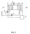
- a reactor compartment 10 houses a NOx reducing catalyst 12 downstream of a SOx removal catalyst 14.
- NOx reducing and SOx removal catalysts are known in the art, and include, for example: SCONOx®.
- SCOSOx® and EMx® which are all commercially available from EmeraChem. LLC of Knoxville, Tennessee.
- Reactor compartment 10 also includes a pair of dampers 16 and 18, which provide a physical barrier that prevents an exhaust gas stream 19 from entering into the reactor compartment during the regeneration sequence.
- a regeneration gas enters into the reactor compartment through a regeneration gas inlet 20.
- Inlet 20 is generally a pipe or other conduit by which the regeneration gas can travel through and enter into reactor compartment 10.
- Inlet 20 may include valves or other controls that regulate the amount of regeneration gas which enters reactor compartment 10.
- Inlet 20 is typically positioned between SOx- removal catalyst 14 and NOx reducing catalyst 12. However, it is contemplated that inlet 20 may be placed at another position in reactor compartment 10.
- the regeneration gas may include hydrogen, natural gas, steam, other inert gases or a mixture thereof.
- the regeneration gas is a mixture of hydrogen carried in steam which contains a small amount of nitrogen and carbon monoxide.
- the regeneration gas typically consists of 2 - 3% hydrogen in a carrier gas such as steam, however other inert gases may be used as the carrier gas.
- Other regeneration gases known in the art to regenerate SOx removal catalyst 14 and NOx reducing catalyst 12 may be used.
- a sulfur removal gas enters reactor compartment 10 through a sulfur removal gas inlet 22.
- the sulfur removal gas is an oxygen-containing gas. Air is one example of a sulfur-removing gas, however other oxygen containing gases, including solely oxygen, may be used.
- the sulfur removal gas is added towards the end of the regeneration sequence to maximize the removal of SOx and other sulfur-containing compounds.
- Reactor compartment 10 may have several valves, which facilitate the movement and the removal of the regeneration gas and sulfur removal gas from the reactor compartment.
- Reactor compartment 10 has a valve 24, which is disposed between damper 16 and NOx reducing catalyst 12.
- Reactor compartment 10 further includes a valve 26 which is disposed between SOx removal catalyst 14 and damper 18. It is contemplated that valves 24 and 26 can be positioned at another location in reactor compartment 10. Valves 24 and 26 are typically connected to pipes or other conduits that allow the regeneration gas and the sulfur removal gas to exit from reactor compartment 10.
- Controller 28 can be any suitable control mechanism. Examples of such include distributed control systems (DCS) and programmable logic control (PLC).
- DCS distributed control systems
- PLC programmable logic control
- the regeneration gas is introduced to the reactor compartment through valve 24 and exits the reactor compartment through valve 26.
- the sulfur removal gas may be introduced by inlet 22 or valve 24.
- This embodiment of reactor compartment 10 does not utilize an inlet 20 to introduce the regeneration gas.
- regeneration of NOx reducing catalyst 12 is always followed by the regeneration of SOx removal catalyst 14.
- NOx reducing catalyst 12 is regenerated first, followed by regeneration of SOx removal catalyst 14.
- SOx removal catalyst 14 is regenerated first, followed by regeneration of NOx reducing catalyst 12, then another regeneration of the SOx removal catalyst 14.
- a sulfur removal gas which is effective to remove excess sulfur and/or SO x compounds from the SOx removal catalyst 14, is introduced into the reactor compartment. Removal of sulfur containing compounds reduces or eliminates sulfur poisoning of NOx reducing catalyst 12.
- reactor compartment 10 which houses SOx removal catalyst 14 and NOx reducing catalyst 12.
- SOx removal catalyst 14 is regenerated only once.
- dampers 16 and 18 are closed to isolate reactor compartment 10 from exhaust gas stream 19.
- valve 24 is opened.
- inlet 20 is opened to introduce the regeneration gas to reactor compartment 10.
- Open valve 24 facilitates the regeneration of NOx reducing catalyst 12 by drawing the regeneration gas through the NOx reducing catalyst.
- the regeneration gas is exhausted by valve 24.
- valves 24 and 26 arc modulated to direct the regeneration gas to SOx removal catalyst 14. Specifically, valve 26 opens while valve 24 is closed. When valve 26 is opened, the regeneration gas is drawn toward valve 26 and through SOx removal catalyst 14. In step 38, SOx removal catalyst 14 is regenerated by the regeneration gas. The regeneration gas is exhausted by valve 26.
- step 40 the sulfur removal gas is introduced to reactor compartment 10. This can be accomplished in at least two ways: (1) close inlet valve 20 to stop the flow of the regeneration gas to into the reactor compartment and open inlet 22 to introduce a sulfur removal gas; or (2) leave inlet 20 open and open inlet 22 to introduce the sulfur removal gas. In either instance, since valve 26 remains open, the sulfur removal gas is drawn through SOx removal catalyst 14, thereby removing SOx therefrom.
- step 42 inlet 22 is closed, which stops the flow of the sulfur removal gas to reactor compartment 10.
- step 44 all remaining open valves are closed, including valve 26 and valve 20, and dampers 16 and 18 are opened, thereby introducing exhaust gas stream 19 to reactor compartment 10.
- SOx removal catalyst 14 is regenerated first, followed by regeneration of NOx reducing catalyst 12 and a second regeneration of the SOx removal catalyst.
- step 50 dampers 16 and 18 close to isolate reactor compartment 10 from exhaust gas stream 19.
- step 52 valve 26 is opened.
- inlet 20 is opened to introduce the regeneration gas to reactor compartment 10.
- Open valve 26 facilitates the regeneration of SOx removal catalyst 14. By opening valve 26 the regeneration gas is drawn towards valve 26 and through SOx removal catalyst 14. The regeneration gas regenerates SOx removal catalyst 14 and is exhausted by valve 26.
- valves 24 and 26 are modulated to direct the regeneration gas to NOx reducing catalyst 12.
- valve 24 opens while valve 26 is closed.
- the regeneration gas is drawn toward valve 24 and through NOx reducing catalyst 12.
- NOx reducing catalyst 12 is regenerated by the regeneration gas, and the regeneration gas is exhausted by valve 24.
- valve 26 is opened while valve 24 is closed. Opening valve 26 again draws the regeneration gas through SOx removal catalyst 14, thereby regenerating the SOx removal catalyst for a second time.
- inlet 20 is closed to stop the flow of the regeneration gas to reactor compartment 10.
- step 64 inlet 22 is opened to introduce a sulfur removal gas to SOx removal catalyst 14. Since valve 26 remains open, the sulfur removal gas is drawn towards open valve 26 and through SOx removal catalyst 14. The sulfur removal gas removes excess sulfur containing compounds and prevents them from slipping over to NOx reducing catalyst 12.
- step 66 After SOx removal catalyst 14 has been exposed to the sulfur removal gas for an amount of time sufficient to remove the sulfur containing compounds, in step 66, inlet 22 closes, dampers 16 and 18 are opened, valve 26 closes, and exhaust gas stream 19 is introduced to compartment 10. The sulfur removal gas and any remaining regeneration gas are removed when dampers 16 and 18 open.
- the regeneration gas is introduced via valve 24.
- Such a reactor compartment is illustrated in FIG.2 and the regeneration sequence is illustrated in FIG. 5 .
- step 70 dampers 16 and 18 are closed, thereby isolating reactor compartment 10 from exhaust gas stream 19.
- step 72 valves 24 and 26 are both opened.
- step 74 a regeneration, gas is introduced to reactor compartment 10 by valve 24. Because valve 26 is open, the regeneration gas flows through and regenerates NOx reducing catalyst 12 and then regenerates SOx removal catalyst 14. The regeneration gas is exhausted from valve 26.
- a sulfur removal gas is introduced to reactor compartment 10.
- valve 24 is closed and the sulfur removal gas is introduced via inlet 22.
- the sulfur removal gas can be introduced via valve 24.
- valve 24 is not closed and instead remains open.
- valve 26 Since valve 26 remains open, the sulfur removal gas is drawn through SOx removal catalyst 14 and exhausted from valve 26.
- step 78 the valve or inlet introducing the sulfur removal gas closes, valve 26 closes and dampers 16 and 18 open, thereby introducing exhaust gas 19 to reactor compartment 10.
- SOx removal catalyst 14 and NOx reducing catalyst 12 are exposed to the regeneration gas for a time sufficient to regenerate the catalysts.
- the time period is determined by the absorption capacity and the volume of the catalysts, however, typically the catalysts are exposed to the regeneration gas for a time period of three or more minutes.
- the sulfur removal gas is added to reactor compartment 10 for a time between about 5 to about 30 seconds, but could be added for up to several minutes, depending on the parameters of the particular system.
- the regeneration sequence takes about 3 to 10 minutes.
- the addition of the sulfur removal gas represents roughly I % to 15% of the total regeneration time.
- the introduction of the sulfur removal gas reduces the amount of breakthrough sulfur to less than 1/3 of the amount which breaks through during the current regeneration sequence not utilizing sulfur removal gas.
- the sulfur removal gas results in higher working capacity of the SOx removal catalyst as more SO 2 has been removed from it. This in turn results in less SO 2 escaping the SOx removal catalyst to poison the NOx reducing catalyst during the sorption process.
- the presently described regeneration sequence substantially or totally eliminates the "puff" of sulfur, which is often released during traditional regeneration sequences. Accordingly, upon re-introducing the exhaust gas into the SOx removal and NOx reducing catalysts, a sulfur puff is no longer entrained into the exhaust gas and brought to the NOx reducing catalyst.
Landscapes
- Engineering & Computer Science (AREA)
- Chemical & Material Sciences (AREA)
- Combustion & Propulsion (AREA)
- Mechanical Engineering (AREA)
- General Engineering & Computer Science (AREA)
- Chemical Kinetics & Catalysis (AREA)
- Health & Medical Sciences (AREA)
- Toxicology (AREA)
- Biomedical Technology (AREA)
- Environmental & Geological Engineering (AREA)
- Analytical Chemistry (AREA)
- General Chemical & Material Sciences (AREA)
- Oil, Petroleum & Natural Gas (AREA)
- Exhaust Gas Treatment By Means Of Catalyst (AREA)
- Exhaust Gas After Treatment (AREA)
- Catalysts (AREA)
Applications Claiming Priority (2)
| Application Number | Priority Date | Filing Date | Title |
|---|---|---|---|
| US11/644,376 US7563423B2 (en) | 2006-12-22 | 2006-12-22 | Method and apparatus for catalyst regeneration |
| PCT/US2007/087872 WO2008079808A1 (en) | 2006-12-22 | 2007-12-18 | A method and apparatus for catalyst regeneration |
Publications (2)
| Publication Number | Publication Date |
|---|---|
| EP2097624A1 EP2097624A1 (en) | 2009-09-09 |
| EP2097624B1 true EP2097624B1 (en) | 2011-05-11 |
Family
ID=39387179
Family Applications (1)
| Application Number | Title | Priority Date | Filing Date |
|---|---|---|---|
| EP07869408A Not-in-force EP2097624B1 (en) | 2006-12-22 | 2007-12-18 | A method and apparatus for catalyst regeneration |
Country Status (9)
| Country | Link |
|---|---|
| US (1) | US7563423B2 (pt) |
| EP (1) | EP2097624B1 (pt) |
| KR (1) | KR101144699B1 (pt) |
| CN (1) | CN101600859B (pt) |
| AT (1) | ATE509191T1 (pt) |
| BR (1) | BRPI0721043A8 (pt) |
| CA (1) | CA2671370C (pt) |
| MY (1) | MY154946A (pt) |
| WO (1) | WO2008079808A1 (pt) |
Families Citing this family (6)
| Publication number | Priority date | Publication date | Assignee | Title |
|---|---|---|---|---|
| CA3104178A1 (en) * | 2008-10-31 | 2010-05-06 | Emerachem, Llc | Methods and systems for reducing particulate matter in a gaseous stream |
| US20110039686A1 (en) * | 2009-08-14 | 2011-02-17 | Battelle Memorial Institute | Fast regeneration of sulfur deactivated Ni-based hot biomass syngas cleaning catalysts |
| WO2017078377A2 (ko) * | 2015-11-05 | 2017-05-11 | 한국기계연구원 | 오염된 산화촉매의 재생 수단을 포함하는 공정 배출가스 오염물질 제거장치 |
| KR101777697B1 (ko) * | 2016-03-28 | 2017-09-12 | 희성촉매 주식회사 | 선택적 촉매 환원 반응용 촉매 부분 재생 장치 |
| DE102016219301A1 (de) | 2016-10-05 | 2018-04-05 | Audi Ag | Verfahren und Vorrichtung zur Abgasreinigung |
| KR102753696B1 (ko) * | 2021-09-27 | 2025-01-14 | 에이치디현대중공업 주식회사 | 메탄산화촉매 재생장치 및 재생방법 |
Family Cites Families (10)
| Publication number | Priority date | Publication date | Assignee | Title |
|---|---|---|---|---|
| NL7601371A (nl) * | 1976-02-11 | 1977-08-15 | Shell Int Research | Werkwijze voor het gelijktijdig verwijderen van stikstofoxyden en zwaveloxyden uit een gasstroom. |
| US4142989A (en) * | 1976-08-17 | 1979-03-06 | Kobe Steel, Ltd. | Process for continuously regenerating a degraded catalyst used for removing nitrogen oxides from exhaust gas |
| US4793981A (en) * | 1986-11-19 | 1988-12-27 | The Babcock & Wilcox Company | Integrated injection and bag filter house system for SOx -NOx -particulate control with reagent/catalyst regeneration |
| US5451558A (en) | 1994-02-04 | 1995-09-19 | Goal Line Environmental Technologies | Process for the reaction and absorption of gaseous air pollutants, apparatus therefor and method of making the same |
| JP2000516681A (ja) * | 1996-08-19 | 2000-12-12 | フォルクスワーゲン・アクチェンゲゼルシャフト | NOx吸収体を備えた火花点火式内燃機関 |
| JP3645704B2 (ja) | 1997-03-04 | 2005-05-11 | トヨタ自動車株式会社 | 内燃機関の排気浄化装置 |
| CA2397226C (en) | 2000-01-11 | 2009-09-29 | Emerachem, Llc | Process, catalyst system, and apparatus for treating sulfur compound containing effluent |
| DE10049040A1 (de) * | 2000-10-04 | 2002-06-13 | Alstom Switzerland Ltd | Verfahren zur Regeneration einer Katalysatoranlage und Vorrichtung zur Durchführung des Verfahrens |
| US6779339B1 (en) * | 2003-05-02 | 2004-08-24 | The United States Of America As Represented By The Environmental Protection Agency | Method for NOx adsorber desulfation in a multi-path exhaust system |
| US7171801B2 (en) * | 2004-06-24 | 2007-02-06 | Caterpillar Inc | Filter system |
-
2006
- 2006-12-22 US US11/644,376 patent/US7563423B2/en not_active Expired - Fee Related
-
2007
- 2007-12-18 AT AT07869408T patent/ATE509191T1/de not_active IP Right Cessation
- 2007-12-18 CA CA2671370A patent/CA2671370C/en not_active Expired - Fee Related
- 2007-12-18 WO PCT/US2007/087872 patent/WO2008079808A1/en not_active Ceased
- 2007-12-18 BR BRPI0721043A patent/BRPI0721043A8/pt not_active IP Right Cessation
- 2007-12-18 EP EP07869408A patent/EP2097624B1/en not_active Not-in-force
- 2007-12-18 KR KR1020097015264A patent/KR101144699B1/ko not_active Expired - Fee Related
- 2007-12-18 CN CN2007800477682A patent/CN101600859B/zh not_active Expired - Fee Related
- 2007-12-18 MY MYPI20092399A patent/MY154946A/en unknown
Also Published As
| Publication number | Publication date |
|---|---|
| CA2671370C (en) | 2012-03-20 |
| KR20090095655A (ko) | 2009-09-09 |
| BRPI0721043A2 (pt) | 2014-07-29 |
| KR101144699B1 (ko) | 2012-07-11 |
| WO2008079808A1 (en) | 2008-07-03 |
| CA2671370A1 (en) | 2008-07-03 |
| US7563423B2 (en) | 2009-07-21 |
| EP2097624A1 (en) | 2009-09-09 |
| ATE509191T1 (de) | 2011-05-15 |
| US20080152564A1 (en) | 2008-06-26 |
| CN101600859A (zh) | 2009-12-09 |
| MY154946A (en) | 2015-08-28 |
| BRPI0721043A8 (pt) | 2016-12-20 |
| CN101600859B (zh) | 2012-12-12 |
Similar Documents
| Publication | Publication Date | Title |
|---|---|---|
| EP2097624B1 (en) | A method and apparatus for catalyst regeneration | |
| US6946419B2 (en) | Process for the regeneration of a catalyst plant and apparatus for performing the process | |
| KR100204257B1 (ko) | 탈초용 열처리 활성탄, 그 제조방법, 그것을 사용한 탈초방법 및 그것을 사용한 탈초시스템 | |
| TW201021900A (en) | Multiple fixed-fluidized beds for contaminant removal | |
| NZ296438A (en) | Regeneration of catalyst/absorber | |
| JP5431677B2 (ja) | 排気ガス浄化装置 | |
| KR20160067047A (ko) | 연소 엔진에 의해 작동되는 차량용, 특히 선박용 배기 가스 후처리 시스템 | |
| CN113713794B (zh) | 一种利用微波耦合双氧水的脱硫活性炭再生系统及方法 | |
| US7235223B2 (en) | Method for operating a flue gas purification plant | |
| JP4772307B2 (ja) | 乾式脱硫装置、乾式脱硫装置内からの水銀除去方法、及び再生塔 | |
| JP2003144852A (ja) | 消化ガスを燃料とするガスエンジンの排ガス脱硝方法および排ガス脱硝装置 | |
| JP2002066246A (ja) | 消化ガス精製装置 | |
| US5897687A (en) | Ammonia adsorption apparatus | |
| JPH07136456A (ja) | 排ガスの高度脱硫脱硝方法と装置 | |
| JP3744172B2 (ja) | 臭化メチルガスの処理方法及び装置 | |
| JPH07136464A (ja) | 排ガス中の窒素酸化物の処理装置と方法 | |
| JPH06226044A (ja) | アンモニア吸着設備 | |
| JPH0775717A (ja) | 燃焼排ガス中の窒素酸化物の低減方法 | |
| WO2024203112A1 (ja) | 排気処理装置 | |
| JP2007103078A (ja) | 燃料電池システム | |
| JP2024143584A (ja) | 排気処理装置 | |
| GB2394429A (en) | Absorber regeneration | |
| JPH05220328A (ja) | 複数塔におけるガスの処理方法 | |
| JP2005105915A (ja) | エンジンの排気浄化装置 | |
| CN1237471A (zh) | 含铬废催化剂作为脱硫剂的应用方法 |
Legal Events
| Date | Code | Title | Description |
|---|---|---|---|
| PUAI | Public reference made under article 153(3) epc to a published international application that has entered the european phase |
Free format text: ORIGINAL CODE: 0009012 |
|
| 17P | Request for examination filed |
Effective date: 20090519 |
|
| AK | Designated contracting states |
Kind code of ref document: A1 Designated state(s): AT BE BG CH CY CZ DE DK EE ES FI FR GB GR HU IE IS IT LI LT LU LV MC MT NL PL PT RO SE SI SK TR |
|
| DAX | Request for extension of the european patent (deleted) | ||
| 17Q | First examination report despatched |
Effective date: 20100316 |
|
| GRAP | Despatch of communication of intention to grant a patent |
Free format text: ORIGINAL CODE: EPIDOSNIGR1 |
|
| GRAS | Grant fee paid |
Free format text: ORIGINAL CODE: EPIDOSNIGR3 |
|
| GRAA | (expected) grant |
Free format text: ORIGINAL CODE: 0009210 |
|
| AK | Designated contracting states |
Kind code of ref document: B1 Designated state(s): AT BE BG CH CY CZ DE DK EE ES FI FR GB GR HU IE IS IT LI LT LU LV MC MT NL PL PT RO SE SI SK TR |
|
| REG | Reference to a national code |
Ref country code: GB Ref legal event code: FG4D |
|
| REG | Reference to a national code |
Ref country code: CH Ref legal event code: EP |
|
| REG | Reference to a national code |
Ref country code: IE Ref legal event code: FG4D |
|
| REG | Reference to a national code |
Ref country code: DE Ref legal event code: R096 Ref document number: 602007014581 Country of ref document: DE Effective date: 20110622 |
|
| REG | Reference to a national code |
Ref country code: SE Ref legal event code: TRGR |
|
| REG | Reference to a national code |
Ref country code: NL Ref legal event code: T3 |
|
| PG25 | Lapsed in a contracting state [announced via postgrant information from national office to epo] |
Ref country code: LT Free format text: LAPSE BECAUSE OF FAILURE TO SUBMIT A TRANSLATION OF THE DESCRIPTION OR TO PAY THE FEE WITHIN THE PRESCRIBED TIME-LIMIT Effective date: 20110511 Ref country code: PT Free format text: LAPSE BECAUSE OF FAILURE TO SUBMIT A TRANSLATION OF THE DESCRIPTION OR TO PAY THE FEE WITHIN THE PRESCRIBED TIME-LIMIT Effective date: 20110912 |
|
| PG25 | Lapsed in a contracting state [announced via postgrant information from national office to epo] |
Ref country code: SI Free format text: LAPSE BECAUSE OF FAILURE TO SUBMIT A TRANSLATION OF THE DESCRIPTION OR TO PAY THE FEE WITHIN THE PRESCRIBED TIME-LIMIT Effective date: 20110511 Ref country code: LV Free format text: LAPSE BECAUSE OF FAILURE TO SUBMIT A TRANSLATION OF THE DESCRIPTION OR TO PAY THE FEE WITHIN THE PRESCRIBED TIME-LIMIT Effective date: 20110511 Ref country code: AT Free format text: LAPSE BECAUSE OF FAILURE TO SUBMIT A TRANSLATION OF THE DESCRIPTION OR TO PAY THE FEE WITHIN THE PRESCRIBED TIME-LIMIT Effective date: 20110511 Ref country code: IS Free format text: LAPSE BECAUSE OF FAILURE TO SUBMIT A TRANSLATION OF THE DESCRIPTION OR TO PAY THE FEE WITHIN THE PRESCRIBED TIME-LIMIT Effective date: 20110911 Ref country code: GR Free format text: LAPSE BECAUSE OF FAILURE TO SUBMIT A TRANSLATION OF THE DESCRIPTION OR TO PAY THE FEE WITHIN THE PRESCRIBED TIME-LIMIT Effective date: 20110812 Ref country code: FI Free format text: LAPSE BECAUSE OF FAILURE TO SUBMIT A TRANSLATION OF THE DESCRIPTION OR TO PAY THE FEE WITHIN THE PRESCRIBED TIME-LIMIT Effective date: 20110511 Ref country code: ES Free format text: LAPSE BECAUSE OF FAILURE TO SUBMIT A TRANSLATION OF THE DESCRIPTION OR TO PAY THE FEE WITHIN THE PRESCRIBED TIME-LIMIT Effective date: 20110822 Ref country code: CY Free format text: LAPSE BECAUSE OF FAILURE TO SUBMIT A TRANSLATION OF THE DESCRIPTION OR TO PAY THE FEE WITHIN THE PRESCRIBED TIME-LIMIT Effective date: 20110511 |
|
| PG25 | Lapsed in a contracting state [announced via postgrant information from national office to epo] |
Ref country code: EE Free format text: LAPSE BECAUSE OF FAILURE TO SUBMIT A TRANSLATION OF THE DESCRIPTION OR TO PAY THE FEE WITHIN THE PRESCRIBED TIME-LIMIT Effective date: 20110511 Ref country code: CZ Free format text: LAPSE BECAUSE OF FAILURE TO SUBMIT A TRANSLATION OF THE DESCRIPTION OR TO PAY THE FEE WITHIN THE PRESCRIBED TIME-LIMIT Effective date: 20110511 |
|
| PG25 | Lapsed in a contracting state [announced via postgrant information from national office to epo] |
Ref country code: PL Free format text: LAPSE BECAUSE OF FAILURE TO SUBMIT A TRANSLATION OF THE DESCRIPTION OR TO PAY THE FEE WITHIN THE PRESCRIBED TIME-LIMIT Effective date: 20110511 Ref country code: SK Free format text: LAPSE BECAUSE OF FAILURE TO SUBMIT A TRANSLATION OF THE DESCRIPTION OR TO PAY THE FEE WITHIN THE PRESCRIBED TIME-LIMIT Effective date: 20110511 Ref country code: DK Free format text: LAPSE BECAUSE OF FAILURE TO SUBMIT A TRANSLATION OF THE DESCRIPTION OR TO PAY THE FEE WITHIN THE PRESCRIBED TIME-LIMIT Effective date: 20110511 Ref country code: RO Free format text: LAPSE BECAUSE OF FAILURE TO SUBMIT A TRANSLATION OF THE DESCRIPTION OR TO PAY THE FEE WITHIN THE PRESCRIBED TIME-LIMIT Effective date: 20110511 |
|
| PLBE | No opposition filed within time limit |
Free format text: ORIGINAL CODE: 0009261 |
|
| STAA | Information on the status of an ep patent application or granted ep patent |
Free format text: STATUS: NO OPPOSITION FILED WITHIN TIME LIMIT |
|
| 26N | No opposition filed |
Effective date: 20120214 |
|
| PG25 | Lapsed in a contracting state [announced via postgrant information from national office to epo] |
Ref country code: IT Free format text: LAPSE BECAUSE OF FAILURE TO SUBMIT A TRANSLATION OF THE DESCRIPTION OR TO PAY THE FEE WITHIN THE PRESCRIBED TIME-LIMIT Effective date: 20110511 |
|
| REG | Reference to a national code |
Ref country code: DE Ref legal event code: R097 Ref document number: 602007014581 Country of ref document: DE Effective date: 20120214 |
|
| PG25 | Lapsed in a contracting state [announced via postgrant information from national office to epo] |
Ref country code: MC Free format text: LAPSE BECAUSE OF NON-PAYMENT OF DUE FEES Effective date: 20111231 |
|
| REG | Reference to a national code |
Ref country code: CH Ref legal event code: PL |
|
| REG | Reference to a national code |
Ref country code: IE Ref legal event code: MM4A |
|
| REG | Reference to a national code |
Ref country code: DE Ref legal event code: R119 Ref document number: 602007014581 Country of ref document: DE Effective date: 20120703 |
|
| PG25 | Lapsed in a contracting state [announced via postgrant information from national office to epo] |
Ref country code: LI Free format text: LAPSE BECAUSE OF NON-PAYMENT OF DUE FEES Effective date: 20111231 Ref country code: DE Free format text: LAPSE BECAUSE OF NON-PAYMENT OF DUE FEES Effective date: 20120703 Ref country code: IE Free format text: LAPSE BECAUSE OF NON-PAYMENT OF DUE FEES Effective date: 20111218 Ref country code: CH Free format text: LAPSE BECAUSE OF NON-PAYMENT OF DUE FEES Effective date: 20111231 |
|
| PG25 | Lapsed in a contracting state [announced via postgrant information from national office to epo] |
Ref country code: MT Free format text: LAPSE BECAUSE OF FAILURE TO SUBMIT A TRANSLATION OF THE DESCRIPTION OR TO PAY THE FEE WITHIN THE PRESCRIBED TIME-LIMIT Effective date: 20110511 |
|
| PG25 | Lapsed in a contracting state [announced via postgrant information from national office to epo] |
Ref country code: LU Free format text: LAPSE BECAUSE OF NON-PAYMENT OF DUE FEES Effective date: 20111218 |
|
| PG25 | Lapsed in a contracting state [announced via postgrant information from national office to epo] |
Ref country code: BG Free format text: LAPSE BECAUSE OF FAILURE TO SUBMIT A TRANSLATION OF THE DESCRIPTION OR TO PAY THE FEE WITHIN THE PRESCRIBED TIME-LIMIT Effective date: 20110811 |
|
| PG25 | Lapsed in a contracting state [announced via postgrant information from national office to epo] |
Ref country code: TR Free format text: LAPSE BECAUSE OF FAILURE TO SUBMIT A TRANSLATION OF THE DESCRIPTION OR TO PAY THE FEE WITHIN THE PRESCRIBED TIME-LIMIT Effective date: 20110511 |
|
| PG25 | Lapsed in a contracting state [announced via postgrant information from national office to epo] |
Ref country code: HU Free format text: LAPSE BECAUSE OF FAILURE TO SUBMIT A TRANSLATION OF THE DESCRIPTION OR TO PAY THE FEE WITHIN THE PRESCRIBED TIME-LIMIT Effective date: 20110511 |
|
| REG | Reference to a national code |
Ref country code: FR Ref legal event code: PLFP Year of fee payment: 9 |
|
| REG | Reference to a national code |
Ref country code: NL Ref legal event code: HC Owner name: GENERAL ELECTRIC TECHNOLOGY GMBH; CH Free format text: DETAILS ASSIGNMENT: VERANDERING VAN EIGENAAR(S), VERANDERING VAN NAAM VAN DE EIGENAAR(S); FORMER OWNER NAME: ALSTOM TECHNOLOGY LTD Effective date: 20160623 |
|
| REG | Reference to a national code |
Ref country code: FR Ref legal event code: PLFP Year of fee payment: 10 |
|
| REG | Reference to a national code |
Ref country code: FR Ref legal event code: CD Owner name: ALSTOM TECHNOLOGY LTD, CH Effective date: 20161124 |
|
| PGFP | Annual fee paid to national office [announced via postgrant information from national office to epo] |
Ref country code: GB Payment date: 20161228 Year of fee payment: 10 Ref country code: NL Payment date: 20161226 Year of fee payment: 10 |
|
| PGFP | Annual fee paid to national office [announced via postgrant information from national office to epo] |
Ref country code: SE Payment date: 20161129 Year of fee payment: 10 Ref country code: FR Payment date: 20161227 Year of fee payment: 10 |
|
| PGFP | Annual fee paid to national office [announced via postgrant information from national office to epo] |
Ref country code: BE Payment date: 20161227 Year of fee payment: 10 |
|
| REG | Reference to a national code |
Ref country code: NL Ref legal event code: MM Effective date: 20180101 |
|
| GBPC | Gb: european patent ceased through non-payment of renewal fee |
Effective date: 20171218 |
|
| PG25 | Lapsed in a contracting state [announced via postgrant information from national office to epo] |
Ref country code: SE Free format text: LAPSE BECAUSE OF NON-PAYMENT OF DUE FEES Effective date: 20171219 |
|
| PG25 | Lapsed in a contracting state [announced via postgrant information from national office to epo] |
Ref country code: NL Free format text: LAPSE BECAUSE OF NON-PAYMENT OF DUE FEES Effective date: 20180101 |
|
| REG | Reference to a national code |
Ref country code: FR Ref legal event code: ST Effective date: 20180831 |
|
| REG | Reference to a national code |
Ref country code: BE Ref legal event code: HC Owner name: GENERAL ELECTRIC TECHNOLOGY GMBH; CH Free format text: DETAILS ASSIGNMENT: CHANGE OF OWNER(S), CHANGEMENT NOM PROPRIETAIRE; FORMER OWNER NAME: ALSTOM TECHNOLOGY LTD Effective date: 20160705 Ref country code: BE Ref legal event code: MM Effective date: 20171231 |
|
| PG25 | Lapsed in a contracting state [announced via postgrant information from national office to epo] |
Ref country code: FR Free format text: LAPSE BECAUSE OF NON-PAYMENT OF DUE FEES Effective date: 20180102 |
|
| PG25 | Lapsed in a contracting state [announced via postgrant information from national office to epo] |
Ref country code: GB Free format text: LAPSE BECAUSE OF NON-PAYMENT OF DUE FEES Effective date: 20171218 Ref country code: BE Free format text: LAPSE BECAUSE OF NON-PAYMENT OF DUE FEES Effective date: 20171231 |