EP2097660B1 - Betätigungsvorrichtung für eine differentialsperre in einem fahrzeug - Google Patents
Betätigungsvorrichtung für eine differentialsperre in einem fahrzeug Download PDFInfo
- Publication number
- EP2097660B1 EP2097660B1 EP07852178.8A EP07852178A EP2097660B1 EP 2097660 B1 EP2097660 B1 EP 2097660B1 EP 07852178 A EP07852178 A EP 07852178A EP 2097660 B1 EP2097660 B1 EP 2097660B1
- Authority
- EP
- European Patent Office
- Prior art keywords
- connecting means
- operating
- operating device
- limbs
- fork
- Prior art date
- Legal status (The legal status is an assumption and is not a legal conclusion. Google has not performed a legal analysis and makes no representation as to the accuracy of the status listed.)
- Active
Links
Images



Classifications
-
- F—MECHANICAL ENGINEERING; LIGHTING; HEATING; WEAPONS; BLASTING
- F16—ENGINEERING ELEMENTS AND UNITS; GENERAL MEASURES FOR PRODUCING AND MAINTAINING EFFECTIVE FUNCTIONING OF MACHINES OR INSTALLATIONS; THERMAL INSULATION IN GENERAL
- F16H—GEARING
- F16H48/00—Differential gearings
- F16H48/20—Arrangements for suppressing or influencing the differential action, e.g. locking devices
- F16H48/30—Arrangements for suppressing or influencing the differential action, e.g. locking devices using externally-actuatable means
-
- F—MECHANICAL ENGINEERING; LIGHTING; HEATING; WEAPONS; BLASTING
- F16—ENGINEERING ELEMENTS AND UNITS; GENERAL MEASURES FOR PRODUCING AND MAINTAINING EFFECTIVE FUNCTIONING OF MACHINES OR INSTALLATIONS; THERMAL INSULATION IN GENERAL
- F16H—GEARING
- F16H48/00—Differential gearings
- F16H48/06—Differential gearings with gears having orbital motion
- F16H48/08—Differential gearings with gears having orbital motion comprising bevel gears
-
- F—MECHANICAL ENGINEERING; LIGHTING; HEATING; WEAPONS; BLASTING
- F16—ENGINEERING ELEMENTS AND UNITS; GENERAL MEASURES FOR PRODUCING AND MAINTAINING EFFECTIVE FUNCTIONING OF MACHINES OR INSTALLATIONS; THERMAL INSULATION IN GENERAL
- F16H—GEARING
- F16H48/00—Differential gearings
- F16H48/20—Arrangements for suppressing or influencing the differential action, e.g. locking devices
- F16H48/24—Arrangements for suppressing or influencing the differential action, e.g. locking devices using positive clutches or brakes
-
- F—MECHANICAL ENGINEERING; LIGHTING; HEATING; WEAPONS; BLASTING
- F16—ENGINEERING ELEMENTS AND UNITS; GENERAL MEASURES FOR PRODUCING AND MAINTAINING EFFECTIVE FUNCTIONING OF MACHINES OR INSTALLATIONS; THERMAL INSULATION IN GENERAL
- F16H—GEARING
- F16H48/00—Differential gearings
- F16H48/20—Arrangements for suppressing or influencing the differential action, e.g. locking devices
- F16H48/30—Arrangements for suppressing or influencing the differential action, e.g. locking devices using externally-actuatable means
- F16H48/34—Arrangements for suppressing or influencing the differential action, e.g. locking devices using externally-actuatable means using electromagnetic or electric actuators
-
- F—MECHANICAL ENGINEERING; LIGHTING; HEATING; WEAPONS; BLASTING
- F16—ENGINEERING ELEMENTS AND UNITS; GENERAL MEASURES FOR PRODUCING AND MAINTAINING EFFECTIVE FUNCTIONING OF MACHINES OR INSTALLATIONS; THERMAL INSULATION IN GENERAL
- F16H—GEARING
- F16H48/00—Differential gearings
- F16H48/20—Arrangements for suppressing or influencing the differential action, e.g. locking devices
- F16H2048/204—Control of arrangements for suppressing differential actions
-
- F—MECHANICAL ENGINEERING; LIGHTING; HEATING; WEAPONS; BLASTING
- F16—ENGINEERING ELEMENTS AND UNITS; GENERAL MEASURES FOR PRODUCING AND MAINTAINING EFFECTIVE FUNCTIONING OF MACHINES OR INSTALLATIONS; THERMAL INSULATION IN GENERAL
- F16H—GEARING
- F16H2200/00—Transmissions for multiple ratios
- F16H2200/20—Transmissions using gears with orbital motion
- F16H2200/203—Transmissions using gears with orbital motion characterised by the engaging friction means not of the freewheel type, e.g. friction clutches or brakes
- F16H2200/2071—Transmissions using gears with orbital motion characterised by the engaging friction means not of the freewheel type, e.g. friction clutches or brakes using three freewheel mechanism
-
- F—MECHANICAL ENGINEERING; LIGHTING; HEATING; WEAPONS; BLASTING
- F16—ENGINEERING ELEMENTS AND UNITS; GENERAL MEASURES FOR PRODUCING AND MAINTAINING EFFECTIVE FUNCTIONING OF MACHINES OR INSTALLATIONS; THERMAL INSULATION IN GENERAL
- F16H—GEARING
- F16H48/00—Differential gearings
- F16H48/20—Arrangements for suppressing or influencing the differential action, e.g. locking devices
- F16H48/30—Arrangements for suppressing or influencing the differential action, e.g. locking devices using externally-actuatable means
- F16H48/32—Arrangements for suppressing or influencing the differential action, e.g. locking devices using externally-actuatable means using fluid pressure actuators
Definitions
- the present invention relates to an operating device for a differential lock in a vehicle according to the preamble of claim 1.
- Vehicles usually have a differential gear between two powered wheels.
- the differential gear makes it possible for the powered wheels to run at different speeds, e.g. when negotiating a bend, while at the same time the differential gear distributes driving power equally to both of the powered wheels.
- On vehicles with more than two powered wheels there may also be a differential gear on each driveshaft between the forward and rear driveshafts.
- the differential effect of a differential gear can be reduced or totally eliminated with a differential lock.
- heavy vehicles e.g.
- the differential gear usually has a differential lock by means of which the powered wheels on a driveshaft, and possibly also a plurality of powered wheels on more than one driveshaft, e.g. in a four-wheel drive system, can be locked relative to one another.
- a differential lock by means of which the powered wheels on a driveshaft, and possibly also a plurality of powered wheels on more than one driveshaft, e.g. in a four-wheel drive system, can be locked relative to one another.
- the differential lock is usually an axial toothed connection in which the engagement movement is effected by means of compressed air and the disengagement movement is usually by means of compressed air or return spring force.
- a differential lock in the form of an axial toothed connection usually comprises a separate connecting means with teeth which engage with/are disengaged from teeth arranged on a differential housing whereby a mechanically firm connection is made/broken in the vehicle's differential gear between powered wheels situated on the same driveshaft but each on their respective side of the vehicle, this being achieved by the driving shafts of these wheels being locked relative to/disconnected from one another in a rotational direction.
- This is effected by the connecting means being movable relative to the driving shaft on one side in its axial direction but fixed in its rotational direction, while at the same time the differential housing is fixed relative to the driving shaft on the other side in its axial direction.
- the separate connecting means is moved into/out of engagement with the differential housing by means of an operating fork which is often a forging.
- a problem with a differential gear with a differential lock as above is that during servicing work which involves removal of the driving shaft on which the separate connecting means is arranged, or during the fitting of this shaft in the course of manufacturing the vehicle, the separate connecting means has to be locked firmly in the operating fork by one or more screws or rivets before said driving shaft is removed/fitted, in order to avoid the separate connecting means being moved out of the operating fork. If the separate connecting means loses contact with the operating fork, this may in the worst case lead to having to remove parts of the gear housing in order to be able to put the connecting means back in a correct position relative to the operating fork.
- US 2,620,055 describes an operating device for a differential lock for a vehicle, which operating device comprises two arc-shaped parts that are screwed and clamped onto the connection means.
- the separate first connecting means has to be locked firmly in the operating fork by one or more screws or rivets before the driving shaft, on which the separate connecting means is arranged, is removed or fitted, in order to prevent the separate connecting means from being moved out of the operating fork.
- the operating device according to claim 1 has the characteristic of the differential lock being engaged by a mechanically firm connection which is effected between the two connecting means such that they are brought into engagement with one another by means of the operating fork.
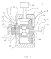
- Figure 1 depicts schematically a gear housing 2 in a vehicle 1 with a differential gear 4 with two driving shafts 6, 8 and an operating device 10 for a differential lock 12 according to a first embodiment of the invention, in which the differential lock operating device 10 comprises a separate connecting means 14 which is movable relative to one driving shaft 6 in its axial direction but fixed in its rotational direction by a mechanical connection 15, e.g. a splined connection, and a second connecting means 16 which is fixed relative to the second driving shaft 8 in its axial direction.
- a mechanical connection 15 e.g. a splined connection
- the separate connecting means 14 is provided with teeth 18, 20 which are adapted to engaging with/being disengaged from teeth 22, 24 arranged on the second connecting means 16 whereby a mechanical firm connection is made/broken in the differential gear 4 of the vehicle 1 between the powered wheels 26, 28 situated on the same driveshaft 30, which driveshaft 30 comprises two driving shafts 6, 8, each on their respective side of the vehicle, this being achieved by these driving shafts 6, 8 of the powered wheels 26, 28 being locked relative to/disengaged from one another in a rotational direction.
- the separate connecting means 14 is moved into/disengaged from the second connecting means 16 by means of an operating fork 32 whose engagement movement is preferably controlled by a cylinder 34 which is preferably a pneumatic cylinder.
- the disengagement movement of the operating fork 32 may be effected by the cylinder 34 or by spring force (not depicted).
- the second connecting means 16 is preferably the differential housing 16 of the differential gear 4, which housing is supported for rotation by bearings 36, 38 in the gear housing 2 in a conventional manner.
- the drawing also shows the input driveshaft 42 to the gear housing 2 from the engine 40 of the vehicle 1.
- the whole or portions of the aforesaid operating cylinder 34 may be situated outside the gear housing 2.
- Figure 2 depicts schematically an operating device 10 for a differential lock 4 according to a first embodiment of the invention and shows the separate connecting means 14 with teeth 18, 20 and internal grooves 44, 46 for fixing the separate connecting means 14 to one driving shaft 6 by mechanical connection.
- the drawing also shows the operating fork 32 and a fastening 48 of the piston 35 of the operating cylinder 34, which fastening is preferably in a recess in the operating fork 32.
- the operating fork 32 is adapted to fitting in a groove 56 of the separate connecting means 14.
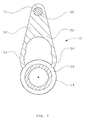
- Figure 3 depicts schematically a cross-section of an operating fork 32 and a separate connecting means 14 of an operating device 10 for a differential lock according to a first embodiment of the invention, in which the operating fork 32 comprises a body 50 with a fastening 48, preferably a recess, for a piston 35 of an operating cylinder, and two limbs 52, 54 which are adapted to fitting in a groove 56 of the separate connecting means 14.
- the operating fork 32 comprises a body 50 with a fastening 48, preferably a recess, for a piston 35 of an operating cylinder, and two limbs 52, 54 which are adapted to fitting in a groove 56 of the separate connecting means 14.
- Figure 4 depicts schematically a cross-section of an operating fork 32 and a separate connecting means 14 of an operating device 10 for a differential lock according to Figure 3 , wherein the operating fork 32 comprises a body 50 with a fastening 48, preferably a recess, for a piston 35 of an operating cylinder 34, and two limbs 52, 54 which are adapted to fitting in a groove 56 of the separate connecting means 14, and wherein it may be seen that when the separate connecting means 14 and the operating fork 32 are fitted together the limbs 52, 54 of the operating fork 32 will spring outwards in the respective directions of the arrows A and B when the limbs 52, 54 of the operating fork 32 pass the cross-sectional centre 57 of the connecting means 14.
- Figure 5 depicts schematically a cross-section of a operating fork and a separate connecting means 14 of an operating device 10 for a differential lock according to Figure 2 , wherein the operating fork 32 comprises a body 50 with a fastening 48, preferably a recess, for a piston 35 of an operating cylinder, and two limbs 52, 54 which are adapted to fitting in a groove 56 of the separate connecting means 14, and wherein it may be seen that when the separate connecting means 14 and the operating fork 32 are fitted together so that the limbs 52, 54 of the operating fork 32 pass the cross-sectional centre 57 of the separate connecting means 14 and the limbs 52, 54 of the operating fork 32 will spring back inwards to their original state depicted in Figure 3 .
- the separate connecting means 14 and the operating fork 32 are fitted together so that the limbs 52, 54 of the operating fork 32 pass the cross-sectional centre 57 of the separate connecting means 14 and the limbs 52, 54 of the operating fork 32 will spring back inward
- the operating fork 32 is arranged with radial clearance 59, 61 in the groove 56 of the separate connecting means 14 during operation, in order to prevent unnecessary wear of the operating fork 32 and the separate connecting means 14 respectively when the separate connecting means 14 rotates with the driving shaft 6.
- This can be achieved with, for example, a guide or protrusion in the gear housing.
- the aforesaid spring effect of the limbs 52, 54 of the operating fork 32 will retain the separate connecting means 14 even if the driving shaft 6 is removed from the separate connecting means 14.
- the operating fork 32 comprises a body 50 which has extending from it two limbs 52, 54 which have their proximal ends 64, 66 connected with one another via the body 50 and their distal ends 68, 70 bent inwards towards one another so that these distal ends 68, 70 are arranged at a distance C from one another which is smaller than diameter D of the portion of the separate connecting means 14 which is bounded by the bottom surface 64 of the groove 56 arranged in the separate connecting means 14.
- the recess between the body 50 of the operating fork 32 and the latter' s limbs 52, 54 is so small that the connecting means 14 will not fall out of the operating fork 32 when the driving shaft 6 is removed.
Landscapes
- Engineering & Computer Science (AREA)
- General Engineering & Computer Science (AREA)
- Mechanical Engineering (AREA)
- Physics & Mathematics (AREA)
- Electromagnetism (AREA)
- Retarders (AREA)
- Arrangement And Mounting Of Devices That Control Transmission Of Motive Force (AREA)
Claims (7)
- Betätigungsvorrichtung (10) für eine Differenzialsperre in einem Fahrzeug (1), wobei die Betätigungsvorrichtung (10) ein separates erstes Verbindungsmittel (14), welches relativ zu einer ersten Antriebswelle (6) in seiner Axialrichtung beweglich aber in seiner Drehrichtung fixiert ist, und ein zweites Verbindungsmittel (16) umfasst, welches in seiner Axialrichtung relativ zu einer zweiten Antriebswelle (8) fixiert ist, und wobei die Differenzialsperre über eine mechanisch starre Verbindung eingelegt wird, welche zwischen den beiden Verbindungsmitteln (14, 16) durch Bewegen des ersten Verbindungsmittels (14) in Eingriff mit dem zweiten Verbindungsmittel (16) mittels einer Betätigungsgabel (32) bewirkt wird, welche einen Körper (50) und zwei zum Passen in eine Nut (56) des ersten Verbindungsmittels (14) eingerichtete Schenkel (52, 54) aufweist,
wobei die proximalen Enden (64, 66) der Schenkel (52, 54) miteinander über den Körper (50) verbunden sind, wobei die proximalen Enden (64, 66) proximal bezüglich des Körpers (50) angeordnet sind, und die distalen Enden (68, 70) der Schenkel (52, 54) einwärts zueinander gebogen sind, wobei die distalen Enden (68, 70) distal bezüglich des Körpers (50) sind,
dadurch gekennzeichnet, dass die distalen Enden (68, 70) der Schenkel (52, 54) in einem Abstand (C) zueinander angeordnet sind, wobei der Abstand (C) kleiner ist als der Querschnittsdurchmesser (D) desjenigen Abschnitts des ersten Verbindungsmittels (14), der von einer unteren Oberfläche (65) der Nut (56) begrenzt ist, in der das erste Verbindungsmittel (14) in der Betätigungsgabel (32) mittels der Schenkel (52, 54) aufgenommen ist, sodass die Schenkel (52, 54) der Betätigungsgabel (32) auswärts federn, wenn sie die Querschnittsmitte (57) des ersten Verbindungsmittels (14) passieren. - Betätigungsvorrichtung (10) nach Anspruch 1,
dadurch gekennzeichnet, dass zwischen den beiden Verbindungsmitteln (14, 16) eine mechanisch starre Verbindung dadurch bewirkt ist, dass an dem ersten Verbindungsmittel (14) Zähne (18, 20) vorgesehen sind, die dazu eingerichtet sind, in am zweiten Verbindungsmittel (16) angeordnete Zähne (22, 24) einzugreifen. - Betätigungsvorrichtung (10) nach Anspruch 1 oder 2,
dadurch gekennzeichnet, dass ein Zylinder (34) dazu angeordnet ist, die Eingriffsbewegung der Betätigungsgabel (32) zu steuern. - Betätigungsvorrichtung (10) nach Anspruch 3,
dadurch gekennzeichnet, dass eine Befestigung (48) für einen Kolben (35) des Zylinders (34) in dem Körper (50) der Betätigungsgabel (32) angeordnet ist. - Betätigungsvorrichtung (10) nach einem der vorangehenden Ansprüche,
dadurch gekennzeichnet, dass das zweite Verbindungsmittel (16) das Differenzialgehäuse (16) des Differenzialgetriebes ist. - Betätigungsvorrichtung (10) nach einem der vorangehenden Ansprüche,
dadurch gekennzeichnet, dass an dem ersten Verbindungsmittel (14) innere Vertiefungen (44, 46) zum Fixieren des ersten Verbindungsmittels (14) an der ersten Antriebswelle (6) in seiner Drehrichtung vorgesehen sind. - Betätigungsvorrichtung (10) nach einem der vorangehenden Ansprüche,
dadurch gekennzeichnet, dass die Betätigungsgabel (32) während des Betriebs mit einem radialen Abstand (59, 61) in der Nut (56) des ersten Verbindungsmittels (14) angeordnet ist, um einen unnötigen Verschleiß der Betätigungsgabel (32) und des ersten Verbindungsmittels (14) jeweils zu vermeiden, wenn sich das erste Verbindungsmittel (14) mit der ersten Antriebswelle (6) dreht.
Applications Claiming Priority (2)
| Application Number | Priority Date | Filing Date | Title |
|---|---|---|---|
| SE0602686A SE530675C2 (sv) | 2006-12-13 | 2006-12-13 | Manöveranordning för differentialspärr |
| PCT/SE2007/050906 WO2008073032A1 (en) | 2006-12-13 | 2007-11-28 | An operating device for a differential lock in a vehicle |
Publications (3)
| Publication Number | Publication Date |
|---|---|
| EP2097660A1 EP2097660A1 (de) | 2009-09-09 |
| EP2097660A4 EP2097660A4 (de) | 2011-03-02 |
| EP2097660B1 true EP2097660B1 (de) | 2014-05-07 |
Family
ID=39511960
Family Applications (1)
| Application Number | Title | Priority Date | Filing Date |
|---|---|---|---|
| EP07852178.8A Active EP2097660B1 (de) | 2006-12-13 | 2007-11-28 | Betätigungsvorrichtung für eine differentialsperre in einem fahrzeug |
Country Status (7)
| Country | Link |
|---|---|
| EP (1) | EP2097660B1 (de) |
| CN (1) | CN101568752B (de) |
| BR (1) | BRPI0718668B1 (de) |
| ES (1) | ES2487502T3 (de) |
| RU (1) | RU2445533C2 (de) |
| SE (1) | SE530675C2 (de) |
| WO (1) | WO2008073032A1 (de) |
Families Citing this family (5)
| Publication number | Priority date | Publication date | Assignee | Title |
|---|---|---|---|---|
| CN102840319B (zh) * | 2012-09-17 | 2016-02-10 | 三一汽车制造有限公司 | 差速锁间隙调整装置及差速锁间隙调整的方法 |
| US9587692B2 (en) | 2015-04-01 | 2017-03-07 | Akebono Brake Industry Co., Ltd | Differential for a parking brake assembly |
| US9477148B1 (en) | 2015-05-26 | 2016-10-25 | Industrial Technology Research Institute | Polymer, method for preparing the same, and a photosensitive resin composition thereof |
| RU2652860C1 (ru) * | 2017-04-13 | 2018-05-03 | Общество с ограниченной ответственностью "Завод механических трансмиссий" | Устройство управления блокировкой дифференциала |
| US11339842B2 (en) | 2019-03-26 | 2022-05-24 | Akebono Brake Industry Co., Ltd. | Brake system with torque distributing assembly |
Family Cites Families (9)
| Publication number | Priority date | Publication date | Assignee | Title |
|---|---|---|---|---|
| US2620055A (en) * | 1948-07-20 | 1952-12-02 | Fasulo Louis | Emergency differential device for motor vehicles |
| FR2604232B1 (fr) * | 1986-09-19 | 1991-04-19 | Glaenzer Spicer Sa | Dispositif de transmission a differentiel, notamment pour vehicule automobile. |
| DE8700373U1 (de) * | 1987-01-09 | 1987-02-26 | Liao, Wen-Tsung, Taitung | Differentialsperre für Kraftfahrzeuge, insbesondere Traktoren |
| IT1210772B (it) * | 1987-05-29 | 1989-09-20 | Fiat Auto Spa | Procedimento di assemblaggio di una leva del cambio di un veicolo eleva del cambio ottenuta con tale procedimento |
| US5342255A (en) * | 1992-11-16 | 1994-08-30 | Eaton Corporation | Locking mechanism for driving axle differential |
| US5673777A (en) * | 1995-08-11 | 1997-10-07 | Eaton Corporation | Differential lock assembly spacer system |
| FR2778444B1 (fr) * | 1998-05-05 | 2000-06-23 | Renault | Boite de vitesses compacte |
| US6432020B1 (en) * | 2000-08-10 | 2002-08-13 | Lazaro Rivera | Differential locking assembly |
| RU2265766C1 (ru) * | 2004-04-26 | 2005-12-10 | Брянская государственная инженерно-технологическая академия | Самоблокирующийся дифференциал колесного транспортного средства |
-
2006
- 2006-12-13 SE SE0602686A patent/SE530675C2/sv unknown
-
2007
- 2007-11-28 WO PCT/SE2007/050906 patent/WO2008073032A1/en not_active Ceased
- 2007-11-28 CN CN200780045558XA patent/CN101568752B/zh active Active
- 2007-11-28 ES ES07852178.8T patent/ES2487502T3/es active Active
- 2007-11-28 BR BRPI0718668-1A patent/BRPI0718668B1/pt active IP Right Grant
- 2007-11-28 EP EP07852178.8A patent/EP2097660B1/de active Active
- 2007-11-28 RU RU2009126570/11A patent/RU2445533C2/ru active
Also Published As
| Publication number | Publication date |
|---|---|
| BRPI0718668A2 (pt) | 2013-11-26 |
| CN101568752A (zh) | 2009-10-28 |
| SE0602686L (sv) | 2008-06-14 |
| RU2445533C2 (ru) | 2012-03-20 |
| CN101568752B (zh) | 2012-03-21 |
| WO2008073032A1 (en) | 2008-06-19 |
| SE530675C2 (sv) | 2008-08-12 |
| BRPI0718668B1 (pt) | 2019-07-30 |
| RU2009126570A (ru) | 2011-01-20 |
| ES2487502T3 (es) | 2014-08-21 |
| EP2097660A4 (de) | 2011-03-02 |
| EP2097660A1 (de) | 2009-09-09 |
Similar Documents
| Publication | Publication Date | Title |
|---|---|---|
| US12117048B2 (en) | Off-road recreational vehicle | |
| JP5941136B2 (ja) | 動力伝達装置 | |
| KR101334082B1 (ko) | 보조 전기 구동 어셈블리 | |
| US6827663B2 (en) | Differential gear | |
| US8469854B1 (en) | Disconnectable driveline for all-wheel drive vehicle | |
| CN108656868B (zh) | 具有离合器套环的组件及制造方法 | |
| US20110127135A1 (en) | Idle-Able Auxiliary Drive System | |
| EP2097660B1 (de) | Betätigungsvorrichtung für eine differentialsperre in einem fahrzeug | |
| JP2003106340A (ja) | ツイン式電子トルク制御装置を備える一体式車軸モジュール | |
| US20220111715A1 (en) | Drive device for a vehicle axle of a vehicle | |
| EP1179464A3 (de) | Fahrzeugbremsregler für Fahrzeuge mit Vierradantrieb | |
| US9751403B2 (en) | Differential assembly and speed sensor mounting arrangement therefor | |
| US20130054104A1 (en) | Drive system for four-wheel drive vehicle, four-wheel drive vehicle, and control method for four-wheel drive vehicle | |
| RU2390433C2 (ru) | Дифференциал повышенного трения | |
| US6931964B2 (en) | Transfer case with multi-gear transfer mechanism | |
| KR101360381B1 (ko) | 구동 장치의 결합해제 | |
| JP7071945B2 (ja) | 車両の制御システム | |
| CN212643475U (zh) | 串列桥系统 | |
| KR20230101063A (ko) | 차량용 차동 기어 장치 | |
| JP4699852B2 (ja) | 4輪駆動車の前後輪駆動力配分装置 | |
| JPH09136555A (ja) | 四輪駆動車両の動力伝達装置 | |
| JPH11118022A (ja) | デファレンシャル装置及びその操作方法 | |
| JPH08324288A (ja) | 四輪駆動装置 | |
| JPH0893882A (ja) | デファレンシャル装置 |
Legal Events
| Date | Code | Title | Description |
|---|---|---|---|
| PUAI | Public reference made under article 153(3) epc to a published international application that has entered the european phase |
Free format text: ORIGINAL CODE: 0009012 |
|
| 17P | Request for examination filed |
Effective date: 20090713 |
|
| AK | Designated contracting states |
Kind code of ref document: A1 Designated state(s): AT BE BG CH CY CZ DE DK EE ES FI FR GB GR HU IE IS IT LI LT LU LV MC MT NL PL PT RO SE SI SK TR |
|
| DAX | Request for extension of the european patent (deleted) | ||
| A4 | Supplementary search report drawn up and despatched |
Effective date: 20110131 |
|
| 17Q | First examination report despatched |
Effective date: 20111010 |
|
| GRAP | Despatch of communication of intention to grant a patent |
Free format text: ORIGINAL CODE: EPIDOSNIGR1 |
|
| INTG | Intention to grant announced |
Effective date: 20131206 |
|
| GRAS | Grant fee paid |
Free format text: ORIGINAL CODE: EPIDOSNIGR3 |
|
| GRAA | (expected) grant |
Free format text: ORIGINAL CODE: 0009210 |
|
| AK | Designated contracting states |
Kind code of ref document: B1 Designated state(s): AT BE BG CH CY CZ DE DK EE ES FI FR GB GR HU IE IS IT LI LT LU LV MC MT NL PL PT RO SE SI SK TR |
|
| REG | Reference to a national code |
Ref country code: GB Ref legal event code: FG4D |
|
| REG | Reference to a national code |
Ref country code: AT Ref legal event code: REF Ref document number: 666960 Country of ref document: AT Kind code of ref document: T Effective date: 20140515 |
|
| REG | Reference to a national code |
Ref country code: IE Ref legal event code: FG4D |
|
| REG | Reference to a national code |
Ref country code: DE Ref legal event code: R096 Ref document number: 602007036612 Country of ref document: DE Effective date: 20140618 |
|
| REG | Reference to a national code |
Ref country code: ES Ref legal event code: FG2A Ref document number: 2487502 Country of ref document: ES Kind code of ref document: T3 Effective date: 20140821 |
|
| REG | Reference to a national code |
Ref country code: AT Ref legal event code: MK05 Ref document number: 666960 Country of ref document: AT Kind code of ref document: T Effective date: 20140507 |
|
| REG | Reference to a national code |
Ref country code: NL Ref legal event code: VDEP Effective date: 20140507 |
|
| REG | Reference to a national code |
Ref country code: LT Ref legal event code: MG4D |
|
| PG25 | Lapsed in a contracting state [announced via postgrant information from national office to epo] |
Ref country code: FI Free format text: LAPSE BECAUSE OF FAILURE TO SUBMIT A TRANSLATION OF THE DESCRIPTION OR TO PAY THE FEE WITHIN THE PRESCRIBED TIME-LIMIT Effective date: 20140507 Ref country code: IS Free format text: LAPSE BECAUSE OF FAILURE TO SUBMIT A TRANSLATION OF THE DESCRIPTION OR TO PAY THE FEE WITHIN THE PRESCRIBED TIME-LIMIT Effective date: 20140907 Ref country code: CY Free format text: LAPSE BECAUSE OF FAILURE TO SUBMIT A TRANSLATION OF THE DESCRIPTION OR TO PAY THE FEE WITHIN THE PRESCRIBED TIME-LIMIT Effective date: 20140507 Ref country code: LT Free format text: LAPSE BECAUSE OF FAILURE TO SUBMIT A TRANSLATION OF THE DESCRIPTION OR TO PAY THE FEE WITHIN THE PRESCRIBED TIME-LIMIT Effective date: 20140507 Ref country code: GR Free format text: LAPSE BECAUSE OF FAILURE TO SUBMIT A TRANSLATION OF THE DESCRIPTION OR TO PAY THE FEE WITHIN THE PRESCRIBED TIME-LIMIT Effective date: 20140808 |
|
| PG25 | Lapsed in a contracting state [announced via postgrant information from national office to epo] |
Ref country code: LV Free format text: LAPSE BECAUSE OF FAILURE TO SUBMIT A TRANSLATION OF THE DESCRIPTION OR TO PAY THE FEE WITHIN THE PRESCRIBED TIME-LIMIT Effective date: 20140507 Ref country code: PL Free format text: LAPSE BECAUSE OF FAILURE TO SUBMIT A TRANSLATION OF THE DESCRIPTION OR TO PAY THE FEE WITHIN THE PRESCRIBED TIME-LIMIT Effective date: 20140507 Ref country code: AT Free format text: LAPSE BECAUSE OF FAILURE TO SUBMIT A TRANSLATION OF THE DESCRIPTION OR TO PAY THE FEE WITHIN THE PRESCRIBED TIME-LIMIT Effective date: 20140507 Ref country code: SE Free format text: LAPSE BECAUSE OF FAILURE TO SUBMIT A TRANSLATION OF THE DESCRIPTION OR TO PAY THE FEE WITHIN THE PRESCRIBED TIME-LIMIT Effective date: 20140507 |
|
| PG25 | Lapsed in a contracting state [announced via postgrant information from national office to epo] |
Ref country code: PT Free format text: LAPSE BECAUSE OF FAILURE TO SUBMIT A TRANSLATION OF THE DESCRIPTION OR TO PAY THE FEE WITHIN THE PRESCRIBED TIME-LIMIT Effective date: 20140908 |
|
| PG25 | Lapsed in a contracting state [announced via postgrant information from national office to epo] |
Ref country code: RO Free format text: LAPSE BECAUSE OF FAILURE TO SUBMIT A TRANSLATION OF THE DESCRIPTION OR TO PAY THE FEE WITHIN THE PRESCRIBED TIME-LIMIT Effective date: 20140507 Ref country code: CZ Free format text: LAPSE BECAUSE OF FAILURE TO SUBMIT A TRANSLATION OF THE DESCRIPTION OR TO PAY THE FEE WITHIN THE PRESCRIBED TIME-LIMIT Effective date: 20140507 Ref country code: BE Free format text: LAPSE BECAUSE OF FAILURE TO SUBMIT A TRANSLATION OF THE DESCRIPTION OR TO PAY THE FEE WITHIN THE PRESCRIBED TIME-LIMIT Effective date: 20140507 Ref country code: EE Free format text: LAPSE BECAUSE OF FAILURE TO SUBMIT A TRANSLATION OF THE DESCRIPTION OR TO PAY THE FEE WITHIN THE PRESCRIBED TIME-LIMIT Effective date: 20140507 Ref country code: DK Free format text: LAPSE BECAUSE OF FAILURE TO SUBMIT A TRANSLATION OF THE DESCRIPTION OR TO PAY THE FEE WITHIN THE PRESCRIBED TIME-LIMIT Effective date: 20140507 Ref country code: SK Free format text: LAPSE BECAUSE OF FAILURE TO SUBMIT A TRANSLATION OF THE DESCRIPTION OR TO PAY THE FEE WITHIN THE PRESCRIBED TIME-LIMIT Effective date: 20140507 |
|
| REG | Reference to a national code |
Ref country code: DE Ref legal event code: R097 Ref document number: 602007036612 Country of ref document: DE |
|
| PG25 | Lapsed in a contracting state [announced via postgrant information from national office to epo] |
Ref country code: NL Free format text: LAPSE BECAUSE OF FAILURE TO SUBMIT A TRANSLATION OF THE DESCRIPTION OR TO PAY THE FEE WITHIN THE PRESCRIBED TIME-LIMIT Effective date: 20140507 |
|
| PLBE | No opposition filed within time limit |
Free format text: ORIGINAL CODE: 0009261 |
|
| STAA | Information on the status of an ep patent application or granted ep patent |
Free format text: STATUS: NO OPPOSITION FILED WITHIN TIME LIMIT |
|
| 26N | No opposition filed |
Effective date: 20150210 |
|
| REG | Reference to a national code |
Ref country code: DE Ref legal event code: R097 Ref document number: 602007036612 Country of ref document: DE Effective date: 20150210 |
|
| PG25 | Lapsed in a contracting state [announced via postgrant information from national office to epo] |
Ref country code: MC Free format text: LAPSE BECAUSE OF FAILURE TO SUBMIT A TRANSLATION OF THE DESCRIPTION OR TO PAY THE FEE WITHIN THE PRESCRIBED TIME-LIMIT Effective date: 20140507 Ref country code: LU Free format text: LAPSE BECAUSE OF FAILURE TO SUBMIT A TRANSLATION OF THE DESCRIPTION OR TO PAY THE FEE WITHIN THE PRESCRIBED TIME-LIMIT Effective date: 20141128 |
|
| REG | Reference to a national code |
Ref country code: CH Ref legal event code: PL |
|
| PG25 | Lapsed in a contracting state [announced via postgrant information from national office to epo] |
Ref country code: SI Free format text: LAPSE BECAUSE OF FAILURE TO SUBMIT A TRANSLATION OF THE DESCRIPTION OR TO PAY THE FEE WITHIN THE PRESCRIBED TIME-LIMIT Effective date: 20140507 Ref country code: LI Free format text: LAPSE BECAUSE OF NON-PAYMENT OF DUE FEES Effective date: 20141130 Ref country code: CH Free format text: LAPSE BECAUSE OF NON-PAYMENT OF DUE FEES Effective date: 20141130 |
|
| REG | Reference to a national code |
Ref country code: IE Ref legal event code: MM4A |
|
| REG | Reference to a national code |
Ref country code: FR Ref legal event code: PLFP Year of fee payment: 9 |
|
| PG25 | Lapsed in a contracting state [announced via postgrant information from national office to epo] |
Ref country code: IE Free format text: LAPSE BECAUSE OF NON-PAYMENT OF DUE FEES Effective date: 20141128 |
|
| PG25 | Lapsed in a contracting state [announced via postgrant information from national office to epo] |
Ref country code: BG Free format text: LAPSE BECAUSE OF FAILURE TO SUBMIT A TRANSLATION OF THE DESCRIPTION OR TO PAY THE FEE WITHIN THE PRESCRIBED TIME-LIMIT Effective date: 20140507 |
|
| PG25 | Lapsed in a contracting state [announced via postgrant information from national office to epo] |
Ref country code: MT Free format text: LAPSE BECAUSE OF FAILURE TO SUBMIT A TRANSLATION OF THE DESCRIPTION OR TO PAY THE FEE WITHIN THE PRESCRIBED TIME-LIMIT Effective date: 20140507 Ref country code: TR Free format text: LAPSE BECAUSE OF FAILURE TO SUBMIT A TRANSLATION OF THE DESCRIPTION OR TO PAY THE FEE WITHIN THE PRESCRIBED TIME-LIMIT Effective date: 20140507 Ref country code: HU Free format text: LAPSE BECAUSE OF FAILURE TO SUBMIT A TRANSLATION OF THE DESCRIPTION OR TO PAY THE FEE WITHIN THE PRESCRIBED TIME-LIMIT; INVALID AB INITIO Effective date: 20071128 |
|
| REG | Reference to a national code |
Ref country code: FR Ref legal event code: PLFP Year of fee payment: 10 |
|
| REG | Reference to a national code |
Ref country code: FR Ref legal event code: PLFP Year of fee payment: 11 |
|
| REG | Reference to a national code |
Ref country code: FR Ref legal event code: PLFP Year of fee payment: 12 |
|
| P01 | Opt-out of the competence of the unified patent court (upc) registered |
Effective date: 20230518 |
|
| PGFP | Annual fee paid to national office [announced via postgrant information from national office to epo] |
Ref country code: ES Payment date: 20231211 Year of fee payment: 17 |
|
| PGFP | Annual fee paid to national office [announced via postgrant information from national office to epo] |
Ref country code: IT Payment date: 20241010 Year of fee payment: 18 |
|
| PGFP | Annual fee paid to national office [announced via postgrant information from national office to epo] |
Ref country code: FR Payment date: 20250930 Year of fee payment: 19 |
|
| REG | Reference to a national code |
Ref country code: ES Ref legal event code: FD2A Effective date: 20260105 |
|
| PGFP | Annual fee paid to national office [announced via postgrant information from national office to epo] |
Ref country code: DE Payment date: 20250930 Year of fee payment: 19 |
|
| PGFP | Annual fee paid to national office [announced via postgrant information from national office to epo] |
Ref country code: GB Payment date: 20251001 Year of fee payment: 19 |
|
| PG25 | Lapsed in a contracting state [announced via postgrant information from national office to epo] |
Ref country code: ES Free format text: LAPSE BECAUSE OF NON-PAYMENT OF DUE FEES Effective date: 20241129 |