EP2097738B1 - Öffnungsbiosensor mit rillen - Google Patents
Öffnungsbiosensor mit rillen Download PDFInfo
- Publication number
- EP2097738B1 EP2097738B1 EP07859396.9A EP07859396A EP2097738B1 EP 2097738 B1 EP2097738 B1 EP 2097738B1 EP 07859396 A EP07859396 A EP 07859396A EP 2097738 B1 EP2097738 B1 EP 2097738B1
- Authority
- EP
- European Patent Office
- Prior art keywords
- aperture
- radiation
- excitation
- analyte
- trench
- Prior art date
- Legal status (The legal status is an assumption and is not a legal conclusion. Google has not performed a legal analysis and makes no representation as to the accuracy of the status listed.)
- Active
Links
Images

Classifications
-
- G—PHYSICS
- G01—MEASURING; TESTING
- G01N—INVESTIGATING OR ANALYSING MATERIALS BY DETERMINING THEIR CHEMICAL OR PHYSICAL PROPERTIES
- G01N21/00—Investigating or analysing materials by the use of optical means, i.e. using sub-millimetre waves, infrared, visible or ultraviolet light
- G01N21/62—Systems in which the material investigated is excited whereby it emits light or causes a change in wavelength of the incident light
- G01N21/63—Systems in which the material investigated is excited whereby it emits light or causes a change in wavelength of the incident light optically excited
- G01N21/64—Fluorescence; Phosphorescence
- G01N21/645—Specially adapted constructive features of fluorimeters
- G01N21/648—Specially adapted constructive features of fluorimeters using evanescent coupling or surface plasmon coupling for the excitation of fluorescence
-
- B—PERFORMING OPERATIONS; TRANSPORTING
- B01—PHYSICAL OR CHEMICAL PROCESSES OR APPARATUS IN GENERAL
- B01L—CHEMICAL OR PHYSICAL LABORATORY APPARATUS FOR GENERAL USE
- B01L2200/00—Solutions for specific problems relating to chemical or physical laboratory apparatus
- B01L2200/02—Adapting objects or devices to another
- B01L2200/025—Align devices or objects to ensure defined positions relative to each other
-
- B—PERFORMING OPERATIONS; TRANSPORTING
- B01—PHYSICAL OR CHEMICAL PROCESSES OR APPARATUS IN GENERAL
- B01L—CHEMICAL OR PHYSICAL LABORATORY APPARATUS FOR GENERAL USE
- B01L2300/00—Additional constructional details
- B01L2300/06—Auxiliary integrated devices, integrated components
- B01L2300/0627—Sensor or part of a sensor is integrated
- B01L2300/0654—Lenses; Optical fibres
-
- B—PERFORMING OPERATIONS; TRANSPORTING
- B01—PHYSICAL OR CHEMICAL PROCESSES OR APPARATUS IN GENERAL
- B01L—CHEMICAL OR PHYSICAL LABORATORY APPARATUS FOR GENERAL USE
- B01L2300/00—Additional constructional details
- B01L2300/08—Geometry, shape and general structure
- B01L2300/0809—Geometry, shape and general structure rectangular shaped
- B01L2300/0816—Cards, e.g. flat sample carriers usually with flow in two horizontal directions
-
- B—PERFORMING OPERATIONS; TRANSPORTING
- B01—PHYSICAL OR CHEMICAL PROCESSES OR APPARATUS IN GENERAL
- B01L—CHEMICAL OR PHYSICAL LABORATORY APPARATUS FOR GENERAL USE
- B01L2300/00—Additional constructional details
- B01L2300/08—Geometry, shape and general structure
- B01L2300/0887—Laminated structure
-
- B—PERFORMING OPERATIONS; TRANSPORTING
- B01—PHYSICAL OR CHEMICAL PROCESSES OR APPARATUS IN GENERAL
- B01L—CHEMICAL OR PHYSICAL LABORATORY APPARATUS FOR GENERAL USE
- B01L3/00—Containers or dishes for laboratory use, e.g. laboratory glassware; Droppers
- B01L3/50—Containers for the purpose of retaining a material to be analysed, e.g. test tubes
- B01L3/502—Containers for the purpose of retaining a material to be analysed, e.g. test tubes with fluid transport, e.g. in multi-compartment structures
- B01L3/5027—Containers for the purpose of retaining a material to be analysed, e.g. test tubes with fluid transport, e.g. in multi-compartment structures by integrated microfluidic structures, i.e. dimensions of channels and chambers are such that surface tension forces are important, e.g. lab-on-a-chip
- B01L3/502715—Containers for the purpose of retaining a material to be analysed, e.g. test tubes with fluid transport, e.g. in multi-compartment structures by integrated microfluidic structures, i.e. dimensions of channels and chambers are such that surface tension forces are important, e.g. lab-on-a-chip characterised by interfacing components, e.g. fluidic, electrical, optical or mechanical interfaces
-
- B—PERFORMING OPERATIONS; TRANSPORTING
- B01—PHYSICAL OR CHEMICAL PROCESSES OR APPARATUS IN GENERAL
- B01L—CHEMICAL OR PHYSICAL LABORATORY APPARATUS FOR GENERAL USE
- B01L3/00—Containers or dishes for laboratory use, e.g. laboratory glassware; Droppers
- B01L3/50—Containers for the purpose of retaining a material to be analysed, e.g. test tubes
- B01L3/502—Containers for the purpose of retaining a material to be analysed, e.g. test tubes with fluid transport, e.g. in multi-compartment structures
- B01L3/5027—Containers for the purpose of retaining a material to be analysed, e.g. test tubes with fluid transport, e.g. in multi-compartment structures by integrated microfluidic structures, i.e. dimensions of channels and chambers are such that surface tension forces are important, e.g. lab-on-a-chip
- B01L3/50273—Containers for the purpose of retaining a material to be analysed, e.g. test tubes with fluid transport, e.g. in multi-compartment structures by integrated microfluidic structures, i.e. dimensions of channels and chambers are such that surface tension forces are important, e.g. lab-on-a-chip characterised by the means or forces applied to move the fluids
-
- B—PERFORMING OPERATIONS; TRANSPORTING
- B01—PHYSICAL OR CHEMICAL PROCESSES OR APPARATUS IN GENERAL
- B01L—CHEMICAL OR PHYSICAL LABORATORY APPARATUS FOR GENERAL USE
- B01L3/00—Containers or dishes for laboratory use, e.g. laboratory glassware; Droppers
- B01L3/50—Containers for the purpose of retaining a material to be analysed, e.g. test tubes
- B01L3/502—Containers for the purpose of retaining a material to be analysed, e.g. test tubes with fluid transport, e.g. in multi-compartment structures
- B01L3/5027—Containers for the purpose of retaining a material to be analysed, e.g. test tubes with fluid transport, e.g. in multi-compartment structures by integrated microfluidic structures, i.e. dimensions of channels and chambers are such that surface tension forces are important, e.g. lab-on-a-chip
- B01L3/502761—Containers for the purpose of retaining a material to be analysed, e.g. test tubes with fluid transport, e.g. in multi-compartment structures by integrated microfluidic structures, i.e. dimensions of channels and chambers are such that surface tension forces are important, e.g. lab-on-a-chip specially adapted for handling suspended solids or molecules independently from the bulk fluid flow, e.g. for trapping or sorting beads or physically stretching molecules
-
- C—CHEMISTRY; METALLURGY
- C12—BIOCHEMISTRY; BEER; SPIRITS; WINE; VINEGAR; MICROBIOLOGY; ENZYMOLOGY; MUTATION OR GENETIC ENGINEERING
- C12Q—MEASURING OR TESTING PROCESSES INVOLVING ENZYMES, NUCLEIC ACIDS OR MICROORGANISMS; COMPOSITIONS OR TEST PAPERS THEREFOR; PROCESSES OF PREPARING SUCH COMPOSITIONS; CONDITION-RESPONSIVE CONTROL IN MICROBIOLOGICAL OR ENZYMOLOGICAL PROCESSES
- C12Q1/00—Measuring or testing processes involving enzymes, nucleic acids or microorganisms; Compositions therefor; Processes of preparing such compositions
- C12Q1/68—Measuring or testing processes involving enzymes, nucleic acids or microorganisms; Compositions therefor; Processes of preparing such compositions involving nucleic acids
- C12Q1/6813—Hybridisation assays
- C12Q1/6834—Enzymatic or biochemical coupling of nucleic acids to a solid phase
- C12Q1/6837—Enzymatic or biochemical coupling of nucleic acids to a solid phase using probe arrays or probe chips
-
- G—PHYSICS
- G01—MEASURING; TESTING
- G01N—INVESTIGATING OR ANALYSING MATERIALS BY DETERMINING THEIR CHEMICAL OR PHYSICAL PROPERTIES
- G01N21/00—Investigating or analysing materials by the use of optical means, i.e. using sub-millimetre waves, infrared, visible or ultraviolet light
- G01N21/84—Systems specially adapted for particular applications
- G01N21/88—Investigating the presence of flaws or contamination
- G01N21/95—Investigating the presence of flaws or contamination characterised by the material or shape of the object to be examined
- G01N21/956—Inspecting patterns on the surface of objects
- G01N2021/95676—Masks, reticles, shadow masks
-
- G—PHYSICS
- G01—MEASURING; TESTING
- G01N—INVESTIGATING OR ANALYSING MATERIALS BY DETERMINING THEIR CHEMICAL OR PHYSICAL PROPERTIES
- G01N21/00—Investigating or analysing materials by the use of optical means, i.e. using sub-millimetre waves, infrared, visible or ultraviolet light
- G01N21/17—Systems in which incident light is modified in accordance with the properties of the material investigated
- G01N21/47—Scattering, i.e. diffuse reflection
-
- G—PHYSICS
- G01—MEASURING; TESTING
- G01N—INVESTIGATING OR ANALYSING MATERIALS BY DETERMINING THEIR CHEMICAL OR PHYSICAL PROPERTIES
- G01N21/00—Investigating or analysing materials by the use of optical means, i.e. using sub-millimetre waves, infrared, visible or ultraviolet light
- G01N21/17—Systems in which incident light is modified in accordance with the properties of the material investigated
- G01N21/55—Specular reflectivity
- G01N21/552—Attenuated total reflection
- G01N21/553—Attenuated total reflection and using surface plasmons
- G01N21/554—Attenuated total reflection and using surface plasmons detecting the surface plasmon resonance of nanostructured metals, e.g. localised surface plasmon resonance
-
- G—PHYSICS
- G01—MEASURING; TESTING
- G01N—INVESTIGATING OR ANALYSING MATERIALS BY DETERMINING THEIR CHEMICAL OR PHYSICAL PROPERTIES
- G01N21/00—Investigating or analysing materials by the use of optical means, i.e. using sub-millimetre waves, infrared, visible or ultraviolet light
- G01N21/62—Systems in which the material investigated is excited whereby it emits light or causes a change in wavelength of the incident light
- G01N21/63—Systems in which the material investigated is excited whereby it emits light or causes a change in wavelength of the incident light optically excited
- G01N21/65—Raman scattering
- G01N21/658—Raman scattering enhancement Raman, e.g. surface plasmons
Definitions
- the present invention relates to the field of biosensors and more specifically to sub-wavelength sensors, namely sub-diffraction limited sensors.
- Biosensor technology is well known in the art.
- US Patent Application No. 2003/0174992 discloses a method and an apparatus for providing a zero-mode waveguide including an analyte, which is subjected to activation by electromagnetic radiation for analyzing the analyte.
- an analyte may be arranged in apertures having at least partly sub-wavelength dimensions.
- the analyte may be included in a fluid.
- a luminophore present in the fluid emits radiation when exposed to excitation energy. The emitted radiation is collected by a detector.
- a disadvantage of these type of biosensors is that the luminescent energy originating from an individual luminophore may depend on the position of the luminophore inside the aperture. As a result, these type of biosensors may have a response that has a poor quantitative relationship to the analyte to be analyzed, resulting in a poor accuracy of the detected property.
- an object of the present invention is to mitigate, alleviate or eliminate one or more of the above-identified deficiencies and disadvantages singly or in any combination.
- a biosensor substrate may comprise an analyte arranged in apertures of a first type having both lateral in-plane dimension below the diffraction limit of the used excitation light in the medium that fills the aperture. These examples are outside the scope of the invention.
- the apertures are of a second type having a first lateral in-plane dimension below the diffraction limit in the medium that fills the apertures and a second lateral in-plane dimension above the diffraction limit in the medium that fills the apertures.
- in-plane dimension is meant the dimension in a plane parallel to the substrate.
- the excitation radiation penetrates into the apertures, but the transmission of the aperture is small and as a result the excitation energy behind the apertures is substantially suppressed.
- the transmission of the aperture is small and as a result the excitation energy behind the apertures is substantially suppressed.
- R-polarized light is defined as light with an electric field in a direction normal to the transmission plane of the aperture, which is a plane normal to the substrate and parallel with a vector along the first dimension of the aperture.
- the detected luminescent energy originates, thus, essentially only from luminophores inside the apertures and a small number of luminophores inside the apertures can be distinguished from the often large number of luminophores outside and behind the aperture.
- the analyte may be included in a fluid.
- a luminophore present in the fluid emits electromagnetic radiation when exposed to excitation energy. The emitted radiation is collected by a detector.
- the total radiation energy i.e. the sum of the radiation energy of the individual luminophores emitted by the luminophores, has a predetermined relationship to a property of the analyte such as being proportional to a concentration of a target molecule of the analyte.
- a property of the analyte such as being proportional to a concentration of a target molecule of the analyte.
- the radiation emitted by the luminophore can be detected at either side of the biosensor substrate. If the analyte fluid is present on one side, the radiation can be detected at the other side.
- the radiation emitted by a luminophore present in the fluid outside the apertures is significantly smaller than the radiation emitted by a luminophore present close to the entrance portion of the aperture, where the excitation light is not attenuated.
- the detected radiation is essentially only radiation emitted by luminophores present close to the entrance portion of the apertures. Hence, a high signal-to-background and signal-to-noise ratio can be obtained since the background radiation may be reduced.
- Ligands or capture molecules may be arranged or immobilized at specific portions of the aperture.
- the said ligands or capture molecules may have an affinity towards target molecules, such that target molecules can bind specifically with the said ligands or capture molecules. As a result the target molecules may bind specifically at said specific portions of the aperture.
- the target molecules may be a luminescent molecule, or may be labeled with a luminescent molecule.
- the thus-formed aggregate of ligands or capture molecules and target molecules forms a luminophore.
- a luminiphore refers to a particle, bead, molecule or aggregate of molecules, or particles, or beads that is capable of emitting luminescent radiation.
- luminophores may take place in different manners, such as described in the article: " Fluorescence spectroscopy of single biomolecules" by S. Weiss, Science, Vol. 283, pp 1676-1683 , the technical contents of which are hereby incorporated by reference.
- luminophore also refers to a luminescently labeled molecule
- the ligands may immobilize the luminophores so that they emit radiation from the immobilized positions at excitation.
- ligands such oligonucleotides, which bind specifically to nucleic acids having a complementary sequence (the target molecules), immobilized at specific portions of the aperture.
- a polymerase chain reaction is often used to amplify the DNA concentration, and fluorescent labeling of the resulting target molecules (amplicons).
- a fragment of the sequence of the amplicons is complementary with and can bind to (hybridize with) the oligonucleotides immobilized at specific portions of the aperture.
- amplicons A fragment of the sequence of the amplicons is complementary with and can bind to (hybridize with) the oligonucleotides immobilized at specific portions of the aperture.
- amplicons A fragment of the sequence of the amplicons is complementary with and can bind to (hybridize with) the oligonucleotides immobilized at specific portions of the aperture.
- a sandwich assay were antibodies specific for the target protein are immobilized at specific portions of the aperture. First the targeted protein molecule binds to the antibody, where after fluorescently labeled antibodies present in the analyte containing fluid bind to the targeted protein molecule. Both examples result in fluorescently labele
- the excitation light and emitted radiation will be attenuated by the aperture in different degrees. This may result in that radiation from luminophores present inside the aperture at the exit side will give a smaller response from the detector compared to the luminophores close to the entrance side. Thus, if luminophores are present all over the aperture, the detector response will not be proportional to the number of luminophores present in the aperture, while luminophores present closer to the entrance portion will contribute more to the detector signal than luminophores present inside the aperture.
- the substrate structure wherein the apertures are defined may be partly or completely composed of a metal, such as aluminum, gold, silver, chromium, etc.
- Luminophores such as fluorophores close (typically less than 10 nm) to a metal can couple their fluorescence to a metal via near field interaction resulting in quenching of the fluorescence.
- the luminescent power for a luminophore close to the metal of the apertures is different than the luminescent power further away from the metal.
- the luminophores may be excited to emit radiation in different manners, such as by electric or chemical energy.
- the emitted radiation may take place by different physical processes, such as luminescence, phosphorescence, fluorescence, Raman scattered light, Hyper-Raman scattered light or Hyper-Rayleight scattered light etc.
- the emitted radiation may be electromagnetic radiation, such as light, including infrared light.
- excitation with electromagnetic radiation will be considered, specifically light, including infrared light, with a wavelength in the relevant medium that is larger than at least one lateral dimension of the aperture.
- the effective wavelength is the wavelength of the radiation in vacuum divided by the refractive index of the medium.
- an evanescent electromagnetic field will be established in the aperture.
- an evanescent electromagnetic field also involves R-polarized light.
- Such an evanescent field may excite the luminophores present in the aperture.
- the evanescent field will have an exponential decay in the aperture from the entrance side or facet of the aperture.
- luminophores present close to the inlet side will be more efficiently excited than luminophores present inside the aperture and beyond the aperture at the other side of the aperture.
- the exit side of the radiation emitted by the luminophores is the same as the inlet side of the excitation radiation.
- the reduced excitation efficiency along the aperture length (which is in a direction normal to a plane that is parallel to the substrate) will add to the attenuation by the aperture of the radiation emitted by the luminophores if the luminophore is present or immobilized inside the aperture at a distance from the inlet/emit side of the aperture.
- excitation radiation will pass through the aperture, although attenuated by the aperture, a typical value for this attenuation is a factor 1000, and exit at the other side of the aperture. Such passing radiation will excite luminophores present in the medium and form background radiation. Such radiation will pass through the apertures in the form of background radiation and add to the signal in the detector. If the useful signal is lowered, as explained above, the signal-to-background and also the signal-to-noise ratio will be lowered.
- the ligand may be attached to a surface at the exit portion of the aperture.
- the ligand has a certain length, which may be for example 1 to 60 nm. Since the length of the aperture may be in the region of 50 to 1000 nm, such ligand length will result in that the luminophores are positioned a substantial distance inside the aperture or in some cases even outside the aperture. Since the excitation energy decays exponentially, the positioning of the ligands inside the aperture will result in that the luminophores are exposed to less excitation energy and, thus, emit less radiation towards the detector.
- the emitted light passes along the aperture and becomes attenuated to a certain degree, also contributing to a decreased of the useful signal. Since the background radiation is unaltered, the decrease of the useful signal results in a reduced signal-to-background and signal-to-noise ratio.
- a ligand immobilized at a surface may have less affinity towards a target molecule if the ligand is positioned close to the surface.
- the ligand may comprise a spacer, further increasing the total ligand length.
- Fig. 1 discloses a biosensor substrate.
- the biosensor substrate comprises a substrate structure 1.
- the substrate structure is substantially opaque or non-transparent for the relevant radiation, such as light at a wavelength (in vacuum) of about 700 nm.
- the substrate structure may be partly or completely composed of a metal, such as gold; aluminum; silver; chromium, etc.
- the material where the substrate structure is partly or completely composed of should have a refractive index having a substantial imaginary component.
- the said imaginary component of the refractive index is preferably larger than 1, more preferably larger than 3 and most preferably larger than 6.
- the substrate structure 1 comprises at least one aperture 2 having a first in-plane lateral dimension smaller than 50 % of an effective wavelength of the medium for filling the aperture.
- Several apertures may be arranged at the surface of the substrate 1, such as with regularly spaced intervals.
- the apertures may be grouped as disclosed in US Patent Application No. 2003/0174992 .
- the aperture may have any shape, such as circular, elliptic, triangular, rectangular, hexagonal, etc.
- the aperture is arranged as a slit having a first in-plane lateral dimension smaller than 50 % of an effective wavelength of the medium for filling the aperture and a second in-plane lateral dimension larger than 50 % of an effective wavelength of the medium for filling the aperture.
- the aperture may be arranged as a combination of two slit arrangements as disclosed in International Patent Application WO2006136991 .
- the first in-plane lateral dimension may be smaller than 40 %, more preferably between 15 % and 25 %, and most preferably between 10% and 15 % of an effective wavelength in the medium for filling the aperture.
- the second in-plane lateral dimension may be between 1 and 10 times, more preferably between 10 and 200 times, and most preferably more than 200 times an effective wavelength in the medium for filling the aperture.
- the wavelength of the excitation light may be around 633 nm, with water (index of refraction 1.33) as a medium for filling the aperture, corresponding with an effective wavelength of 476 nm.
- the first in-plane lateral dimension may be smaller than 190 nm, more preferably between 71 nm and 119 nm, and most preferably between 48 nm and 71 nm.
- the second in-plane lateral dimension may be between 0.48 ⁇ m and 5 ⁇ m, more preferably between 5 ⁇ m and 100 ⁇ m, and most preferably more than 100 ⁇ m.
- the wavelength of the excitation light may be around 350 nm, with water (index of refraction 1.35) as a medium for filling the aperture, corresponding with an effective wavelength of 260 nm.
- the first in-plane lateral dimension may be smaller than 103 nm, more preferably between 39 nm and 65 nm, and most preferably between 26 nm and 391 nm.
- the second in-plane lateral dimension may be between 0.26 ⁇ m and 2.5 ⁇ m, more preferably between 2.5 ⁇ m and 50 ⁇ m, and most preferably more than 50 ⁇ m.
- a transparent structure 3 is arranged below the substrate structure 1 supporting the substrate structure.
- the transparent structure 3 is made of a material that is substantially transparent to the excitation and may also be transparent to the emitted radiation.
- the material may be glass, acrylic glass, epoxy resin, polyvinylchloride (PVC), etc In order to be sufficiently transparent, the material should have a refractive index with an imaginary part smaller than 10 -4 .
- a surface of the transparent structure 3 forms a bottom of the apertures 2 as shown in Fig. 1 .
- the surface is provided with a recess or trench 4 coinciding with the aperture 2.
- the trenches are made by etching the transparent material opposite to the apertures. Other methods of forming the trenches may be to add distance members to the transparent material at regular intervals.
- the surface in the trench 4 is surface modified to include capture molecules such as ligands 5.
- the ligands 5 have an affinity towards target molecules 7 present in a fluid 6, which is present in the aperture 2 and above the substrate 1.
- the target molecules 7 are labeled with a luminophore 8.
- a luminophore is a molecule or particle that generates luminescent radiation when exposed for energy from an excitation source.
- a fluorophore is a molecule or particle that generates electromagnetic radiation, such as light or infrared light by fluorescence when exposed for energy from a light source, including infrared light. Whenever there is referred to fluorescence or a fluorophore in this specification, it can alternatively be intended to mean luminescence or a luminophore.
- the operation of the sensor of Fig. 1 is as follows.
- Target molecules 7 having a fluorophore 8 attached thereto enters the aperture 2 and are caught by ligands 5 immobilized on the surface of the trench 4.
- Three such aggregates 9 of a ligand 5, a target molecule 7 and a flourophore 8 are shown in the trench in Fig. 1 .
- the fluid is substantially water having a refractive index of 1.3.
- the biosensor substrate is exposed to light 10 from the transparent structure 3 side.
- the light 10 has a wavelength of 700 nm in vacuum corresponding to an effective wavelength of 538 nm in water.
- Both lateral in-plane dimensions of the aperture are smaller than about 269 nm, i.e. smaller than 50% of the effective wavelength, such as 70 nm.
- an evanescent electromagnetic field is present inside the aperture with exponentially decaying field strength.
- the biosensor substrate is exposed to R-polarized light 10 from the transparent structure 3 side.
- the R-polarized light 10 has a wavelength of 700 nm in vacuum corresponding to an effective wavelength of 538 nm in water.
- the first lateral in-plane dimensions of the aperture is smaller than about 269 nm, i.e. smaller than 50% of the effective wavelength, such as 70 nm.
- the second lateral in-plane dimension is larger than about 269 nm, i.e. larger than 50% of the effective wavelength, such as 1 mm.
- an evanescent electromagnetic field is present inside the aperture with exponentially decaying field strength.
- wavelength radiation may be used as well such as microwaves, infrared light, near-infrared (NIR) light, visible light, ultraviolet light, X-ray, etc.
- a fluorophore present in aggregate 9a present at the surface of the trench 4 is excited and emits radiation as indicated by arrows 11a and 11b. About 50% of such radiation according to arrow 11a is directed towards a detector 12 present below the sandwich member 3. The other 50% of the emitted radiation as indicated by arrow 11b is directed into the aperture and is attenuated therein. Since the fluorophore is excited by non-attenuated excitation light- due to the reflection of the excitation light 10 by the aperture the energy of the excitation light in the trench is actually increased by about a factor 2, and since a large portion of the emitted radiation reaches the detector, a high efficiency is obtained.
- a fluorophore attached to a target molecule 7 present inside the aperture as indicated by aggregate 9b is exposed to an excitation radiation, which has been greatly attenuated inside the aperture.
- an excitation radiation which has been greatly attenuated inside the aperture.
- fluorophore emits less radiation than the fluorophore present in aggregate 9a, because the power of the emitted fluorescence is proportional to the intensity of the- for fluorophore 9b reduced- excitation radiation.
- the emitted radiation which is directed towards the detector 12 as indicated by arrow 13a, is attenuated by the action of the aperture, which is also relevant for the radiation directed in the other direction as indicated by arrow 13b.
- the attenuation of such radiation is about 1000 and depends- for given lateral dimensions of the aperture- on the length of the aperture.
- the attenuation of the excitation radiation that has passed the aperture is about 1000.
- Such radiation will excite fluorophores present in the fluid, such as fluorophores labeled to the free target molecules as well as free flourophores non-attached to a target molecule.
- fluorophores will emit radiation and a fraction thereof, as indicated by arrow 14a will enter the aperture and pass to the detector 12 again attenuated by the aperture.
- Such radiation 13a and 14a forms background radiation.
- exciting radiation reflected back to the detector will add to the background radiation.
- a wavelength filter that transmits the fluorescent radiation and blocks the excitation radiation may be used to attenuate the reflected excitation radiation.
- the background radiation can be reduced by washing away free target molecules and fluorophores.
- washing may not be possible in real-time measurements.
- some target molecules and fluorophores may stay in spite of such washing.
- the trench has a certain depth corresponding to the length of the ligand 5 so that the luminophore is present at the exit surface of the aperture.
- the target molecules are sandwiched between a first acceptor molecules at the binding interface and a second fluorescently labeled acceptor molecule.
- the depth may be equal to the length of the ligand.
- Sandwich assays it is typically 10 to 60 nm; for peptide-antibody assays it is 3 to 25 nm; for DNA hybridization assays it can be 1 to 15 nm.
- the depth of the trench can be slightly larger than the ligand length, such as 1 to 50 nm larger.
- the depth may be the sum of the ligand length, the size of the target molecule and a predetermined constant.
- a suitable depth is 1 to 60 nm, but a depth up to 1000 nm may be used in certain applications.
- the excitation energy will be substantially attenuated before reaching the flourophores as explained above.
- the detected power of the radiation generated by aggregates 9a may be reduced by a factor of 10 in a practical embodiment, while the detected background radiation remains essentially the same, thus resulting in a reduction of the background suppression.
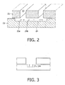
- Fig. 2 discloses another embodiment, in which at least one of the lateral in-plane dimensions of the trench 24 is made substantially larger than the corresponding, that is parallel to, lateral in-plane dimension of the aperture 22.
- the trench may be provided by ligands 25a over the surface corresponding to the apertures. Additionally, the trench may be provided with ligands 25b over the surface in between the apertures.
- ligands are only present opposite to the apertures.
- the trench 34 is only present over a portion of the exit area of the aperture.
- the area between the trenches can form structures for supporting the substrate structure comprising the apertures. If the apertures are formed by a wire structure, the trenches may extend over multiple wires and act as support structure for the wires.
- the trench surface is provided with ligands, which may take place in any conventional manner.
- the ligands may be a protein, a peptide, an antibody or a fragment thereof, a sequence specific probe that is complimentary to the targeted DNA sequence, a carbohydrate, a hormone, an antioxidant, a glycoprotein, a lipoprotein, a reactive dye or combinations thereof.
- the biosensor is operated in reflection mode, wherein the signal is detected at the same side as the excitation radiation is arranged.
- the excitation radiation should be prevented from reaching the detector, which may take place by filters, such as polarizing filters or wavelength filters that block the excitation radiation.
- the same principle may as well be used in transmission mode with the disadvantage that the generated fluorescent radiation is somewhat suppressed because it has to propagate through the apertures.
Landscapes
- Health & Medical Sciences (AREA)
- Nuclear Medicine, Radiotherapy & Molecular Imaging (AREA)
- Physics & Mathematics (AREA)
- Life Sciences & Earth Sciences (AREA)
- Chemical & Material Sciences (AREA)
- Analytical Chemistry (AREA)
- Biochemistry (AREA)
- General Health & Medical Sciences (AREA)
- General Physics & Mathematics (AREA)
- Immunology (AREA)
- Pathology (AREA)
- Investigating, Analyzing Materials By Fluorescence Or Luminescence (AREA)
Claims (7)
- Lumineszenzsensor, der Folgendes umfasst:eine Anregungslichtquelle (10) und ein Sensorsubstrat,wobei das genannte Sensorsubstrat Folgendes umfasst:- eine nicht transparente Substratstruktur (1) mit zumindest einer Öffnung (2), die einen Analyten in einem Medium enthalten soll, wobei die genannte Öffnung ein Schlitz mit einem planaren ersten Seitenmaß unter 50 % einer effektiven Wellenlänge des Anregungslichts in dem Medium und einem zweiten planaren Seitenmaß über 50 % einer effektiven Wellenlänge des Anregungslichts in dem Medium ist,- eine transparente Substratstruktur (3), die unterhalb der genannten nicht transparenten Struktur (1) angeordnet ist,
wobei das genannte Sensorsubstrat so angeordnet ist, dass es von der Seite der transparenten Substratstruktur aus dem Anregungslicht (10) ausgesetzt wird, und wobei das Anregungslicht (10), dem das Sensorsubstrat durch seine Anordnung ausgesetzt wird, in einer Richtung polarisiert wird, die senkrecht zu dem ersten planaren Seitenmaß steht,dadurch gekennzeichnet, dass- die Oberfläche der transparenten Substratstruktur (3), die den Boden der Öffnung (2) bildet, einen Einschnitt (4) aufweist, sodass sich ein Teil der Oberfläche am Boden des Einschnitts (4) in einem vorbestimmten Abstand zum proximalen Ende der genannten Öffnung befindet, wobei der Teil der Oberfläche ein Bindungsvermögen hinsichtlich dem genannten Analyten hat, das größer als das Bindungsvermögen hinsichtlich des genannten Analyten an anderer Stelle auf dem transparenten Substrat ist,- wobei der genannte Teil der Oberfläche zumindest einen Liganden (5, 25a, 25b) mit einer Affinität für in dem Analyten enthaltene Zielmoleküle enthält,- wobei der genannte Abstand ungefähr der durchschnittlichen Länge eines Liganden entspricht. - Sensor nach Anspruch 1, wobei der genannte Abstand der Summe aus der Ligandenlänge, der Zielmolekülgröße und einer konstanten Länge entspricht.
- Sensor nach Anspruch 2, wobei die genannte konstante Länge 1 bis 50 nm beträgt, wie beispielsweise 1 bis 10 nm.
- Sensor nach Anspruch 1, wobei der genannte Abstand 1 bis 60 nm beträgt, wie beispielsweise 3 bis 25 nm.
- Sensor nach Anspruch 1, wobei der genannte Abstand 1 bis 15 nm beträgt.
- Sensor nach Anspruch 1, wobei der genannte Abstand 60 bis 1000 nm beträgt.
- Sensor nach Anspruch 1, wobei der Einschnitt eine Abmessung hat, die der Öffnung entspricht und gegenüber der Öffnung angeordnet ist.
Priority Applications (1)
| Application Number | Priority Date | Filing Date | Title |
|---|---|---|---|
| EP07859396.9A EP2097738B1 (de) | 2006-12-21 | 2007-12-17 | Öffnungsbiosensor mit rillen |
Applications Claiming Priority (3)
| Application Number | Priority Date | Filing Date | Title |
|---|---|---|---|
| EP06126771 | 2006-12-21 | ||
| EP07859396.9A EP2097738B1 (de) | 2006-12-21 | 2007-12-17 | Öffnungsbiosensor mit rillen |
| PCT/IB2007/055159 WO2008078263A1 (en) | 2006-12-21 | 2007-12-17 | Aperture biosensor with trenches |
Publications (2)
| Publication Number | Publication Date |
|---|---|
| EP2097738A1 EP2097738A1 (de) | 2009-09-09 |
| EP2097738B1 true EP2097738B1 (de) | 2013-11-20 |
Family
ID=39296842
Family Applications (1)
| Application Number | Title | Priority Date | Filing Date |
|---|---|---|---|
| EP07859396.9A Active EP2097738B1 (de) | 2006-12-21 | 2007-12-17 | Öffnungsbiosensor mit rillen |
Country Status (5)
| Country | Link |
|---|---|
| US (1) | US9176062B2 (de) |
| EP (1) | EP2097738B1 (de) |
| JP (1) | JP5456483B2 (de) |
| CN (1) | CN101568823B (de) |
| WO (1) | WO2008078263A1 (de) |
Families Citing this family (4)
| Publication number | Priority date | Publication date | Assignee | Title |
|---|---|---|---|---|
| CN101915957B (zh) * | 2006-06-12 | 2012-12-12 | 加利福尼亚太平洋生物科学公司 | 实施分析反应的基材 |
| EP2344021B1 (de) * | 2008-09-23 | 2013-01-23 | GILUPI GmbH | Diagnostisches analyten-sammelgerät auf basis von flexiblen polymeren mit biologischer oberflächenmodifikation und mikrofluidik-funktionalität |
| US10962322B2 (en) | 2013-12-16 | 2021-03-30 | Ravin Crossbows, Llc | Bow string cam arrangement for a compound bow |
| CN114295601B (zh) * | 2021-12-31 | 2024-01-30 | 厦门大学 | 一种基于连续体束缚态的表面拉曼增强传感结构 |
Family Cites Families (16)
| Publication number | Priority date | Publication date | Assignee | Title |
|---|---|---|---|---|
| CA2133643A1 (en) | 1992-04-06 | 1993-10-14 | Stanley R. Bouma | Method and device for detection of nucleic acid or analyte using total internal reflectance |
| US5814565A (en) | 1995-02-23 | 1998-09-29 | University Of Utah Research Foundation | Integrated optic waveguide immunosensor |
| JP3873521B2 (ja) * | 1998-05-08 | 2007-01-24 | 富士ゼロックス株式会社 | 光ヘッドおよびディスク装置 |
| WO2000009757A1 (en) | 1998-08-13 | 2000-02-24 | U.S. Genomics, Inc. | Optically characterizing polymers |
| US6917726B2 (en) * | 2001-09-27 | 2005-07-12 | Cornell Research Foundation, Inc. | Zero-mode clad waveguides for performing spectroscopy with confined effective observation volumes |
| FR2820828B1 (fr) * | 2001-02-09 | 2003-05-02 | Commissariat Energie Atomique | Dispositif d'observation d'echantillons par fluorescence, notamment de facon sequentielle |
| JP4213361B2 (ja) * | 2001-05-22 | 2009-01-21 | パナソニック株式会社 | バイオセンサ |
| US20030136921A1 (en) | 2002-01-23 | 2003-07-24 | Reel Richard T | Methods for fluorescence detection that minimizes undesirable background fluorescence |
| US20030215872A1 (en) * | 2002-05-20 | 2003-11-20 | Clark-Mxr, Inc. | Screening apparatus and method for making |
| KR20060130543A (ko) * | 2003-08-06 | 2006-12-19 | 유니버시티 오브 피츠버그 오브 더 커먼웰쓰 시스템 오브 하이어 에듀케이션 | 표면 플라즈몬-강화 나노-광 소자 및 그의 제조 방법 |
| US7339666B2 (en) * | 2004-09-14 | 2008-03-04 | Hewlett-Packard Development Company, L.P. | Light-amplifying structures and methods for surface-enhanced Raman spectroscopy |
| CN101203743B (zh) | 2005-06-23 | 2011-04-06 | 皇家飞利浦电子股份有限公司 | 使用亚波长孔径或狭缝的发光传感器 |
| WO2007064597A2 (en) * | 2005-11-28 | 2007-06-07 | Pacific Biosciences Of California, Inc. | Uniform surfaces for hybrid material substrates and methods for making and using same |
| EP1966593B1 (de) | 2005-12-20 | 2010-08-25 | Koninklijke Philips Electronics N.V. | Aus einem gitter und einem polarisator zusammengesetzter biosensor mit eindimensionalen sub-diffraktions-begrenzten öffnungen |
| JP2007198801A (ja) * | 2006-01-24 | 2007-08-09 | Univ Waseda | 微小開口膜、生体分子間相互作用解析方法及びその装置 |
| CN101915957B (zh) | 2006-06-12 | 2012-12-12 | 加利福尼亚太平洋生物科学公司 | 实施分析反应的基材 |
-
2007
- 2007-12-17 US US12/519,849 patent/US9176062B2/en not_active Expired - Fee Related
- 2007-12-17 EP EP07859396.9A patent/EP2097738B1/de active Active
- 2007-12-17 JP JP2009542339A patent/JP5456483B2/ja not_active Expired - Fee Related
- 2007-12-17 CN CN2007800478670A patent/CN101568823B/zh not_active Expired - Fee Related
- 2007-12-17 WO PCT/IB2007/055159 patent/WO2008078263A1/en not_active Ceased
Also Published As
| Publication number | Publication date |
|---|---|
| US20100001210A1 (en) | 2010-01-07 |
| EP2097738A1 (de) | 2009-09-09 |
| US9176062B2 (en) | 2015-11-03 |
| JP2010513909A (ja) | 2010-04-30 |
| JP5456483B2 (ja) | 2014-03-26 |
| CN101568823B (zh) | 2013-03-27 |
| CN101568823A (zh) | 2009-10-28 |
| WO2008078263A1 (en) | 2008-07-03 |
Similar Documents
| Publication | Publication Date | Title |
|---|---|---|
| EP3394596B1 (de) | Optische detektion von teilchen in einer flüssigkeit | |
| US20100252751A1 (en) | Microelectronic opiacal evanescent field sensor | |
| US12339233B2 (en) | Optical detection of a substance in fluid | |
| JP2008249361A (ja) | 表面プラズモンセンサーおよび免疫学的測定方法 | |
| JP2008544276A (ja) | サブ波長アパーチャ又はスリットを用いた発光センサ | |
| WO2010134592A1 (ja) | Spfs-lpfs系による測定方法に供するプラズモン励起センサおよびアッセイ法 | |
| JP2010145272A (ja) | プラズモン励起センサを用いたアッセイ法 | |
| EP2097738B1 (de) | Öffnungsbiosensor mit rillen | |
| US8039814B2 (en) | Luminescence sensor operating in reflection mode | |
| WO2009063368A2 (en) | Plasmon grating biosensor | |
| US7615760B2 (en) | Luminescence sensor comprising at least two wire grids | |
| EP2112500A1 (de) | Plasmonischer Biosensor | |
| RU2494374C2 (ru) | Устройство микроэлектронного датчика | |
| US9891171B2 (en) | Sensing module and sensing method | |
| JP2005077396A (ja) | 分析用光導波路 | |
| Knoll et al. | Principles and applications of surface-plasmon field-enhanced fluorescence techniques | |
| WO2009060350A1 (en) | Microelectronic sensor device | |
| JP2010169519A (ja) | プラズモン励起センサおよびそれを用いたアッセイ法 | |
| JP2012032281A (ja) | プラズモン励起センサおよび該センサを用いたアッセイ法 | |
| JP2010169518A (ja) | プラズモン励起センサおよびそれを用いたアッセイ法 |
Legal Events
| Date | Code | Title | Description |
|---|---|---|---|
| PUAI | Public reference made under article 153(3) epc to a published international application that has entered the european phase |
Free format text: ORIGINAL CODE: 0009012 |
|
| 17P | Request for examination filed |
Effective date: 20090721 |
|
| AK | Designated contracting states |
Kind code of ref document: A1 Designated state(s): AT BE BG CH CY CZ DE DK EE ES FI FR GB GR HU IE IS IT LI LT LU LV MC MT NL PL PT RO SE SI SK TR |
|
| DAX | Request for extension of the european patent (deleted) | ||
| 17Q | First examination report despatched |
Effective date: 20101206 |
|
| GRAP | Despatch of communication of intention to grant a patent |
Free format text: ORIGINAL CODE: EPIDOSNIGR1 |
|
| INTG | Intention to grant announced |
Effective date: 20130624 |
|
| RAP1 | Party data changed (applicant data changed or rights of an application transferred) |
Owner name: KONINKLIJKE PHILIPS N.V. |
|
| GRAS | Grant fee paid |
Free format text: ORIGINAL CODE: EPIDOSNIGR3 |
|
| GRAA | (expected) grant |
Free format text: ORIGINAL CODE: 0009210 |
|
| AK | Designated contracting states |
Kind code of ref document: B1 Designated state(s): AT BE BG CH CY CZ DE DK EE ES FI FR GB GR HU IE IS IT LI LT LU LV MC MT NL PL PT RO SE SI SK TR |
|
| REG | Reference to a national code |
Ref country code: GB Ref legal event code: FG4D |
|
| REG | Reference to a national code |
Ref country code: CH Ref legal event code: EP |
|
| REG | Reference to a national code |
Ref country code: AT Ref legal event code: REF Ref document number: 641921 Country of ref document: AT Kind code of ref document: T Effective date: 20131215 |
|
| REG | Reference to a national code |
Ref country code: IE Ref legal event code: FG4D |
|
| REG | Reference to a national code |
Ref country code: DE Ref legal event code: R096 Ref document number: 602007033958 Country of ref document: DE Effective date: 20140116 |
|
| REG | Reference to a national code |
Ref country code: NL Ref legal event code: VDEP Effective date: 20131120 |
|
| REG | Reference to a national code |
Ref country code: AT Ref legal event code: MK05 Ref document number: 641921 Country of ref document: AT Kind code of ref document: T Effective date: 20131120 |
|
| REG | Reference to a national code |
Ref country code: LT Ref legal event code: MG4D |
|
| PG25 | Lapsed in a contracting state [announced via postgrant information from national office to epo] |
Ref country code: IS Free format text: LAPSE BECAUSE OF FAILURE TO SUBMIT A TRANSLATION OF THE DESCRIPTION OR TO PAY THE FEE WITHIN THE PRESCRIBED TIME-LIMIT Effective date: 20140320 Ref country code: FI Free format text: LAPSE BECAUSE OF FAILURE TO SUBMIT A TRANSLATION OF THE DESCRIPTION OR TO PAY THE FEE WITHIN THE PRESCRIBED TIME-LIMIT Effective date: 20131120 Ref country code: SE Free format text: LAPSE BECAUSE OF FAILURE TO SUBMIT A TRANSLATION OF THE DESCRIPTION OR TO PAY THE FEE WITHIN THE PRESCRIBED TIME-LIMIT Effective date: 20131120 Ref country code: NL Free format text: LAPSE BECAUSE OF FAILURE TO SUBMIT A TRANSLATION OF THE DESCRIPTION OR TO PAY THE FEE WITHIN THE PRESCRIBED TIME-LIMIT Effective date: 20131120 Ref country code: LT Free format text: LAPSE BECAUSE OF FAILURE TO SUBMIT A TRANSLATION OF THE DESCRIPTION OR TO PAY THE FEE WITHIN THE PRESCRIBED TIME-LIMIT Effective date: 20131120 |
|
| PG25 | Lapsed in a contracting state [announced via postgrant information from national office to epo] |
Ref country code: AT Free format text: LAPSE BECAUSE OF FAILURE TO SUBMIT A TRANSLATION OF THE DESCRIPTION OR TO PAY THE FEE WITHIN THE PRESCRIBED TIME-LIMIT Effective date: 20131120 Ref country code: LV Free format text: LAPSE BECAUSE OF FAILURE TO SUBMIT A TRANSLATION OF THE DESCRIPTION OR TO PAY THE FEE WITHIN THE PRESCRIBED TIME-LIMIT Effective date: 20131120 Ref country code: BE Free format text: LAPSE BECAUSE OF FAILURE TO SUBMIT A TRANSLATION OF THE DESCRIPTION OR TO PAY THE FEE WITHIN THE PRESCRIBED TIME-LIMIT Effective date: 20131120 Ref country code: ES Free format text: LAPSE BECAUSE OF FAILURE TO SUBMIT A TRANSLATION OF THE DESCRIPTION OR TO PAY THE FEE WITHIN THE PRESCRIBED TIME-LIMIT Effective date: 20131120 |
|
| PG25 | Lapsed in a contracting state [announced via postgrant information from national office to epo] |
Ref country code: PT Free format text: LAPSE BECAUSE OF FAILURE TO SUBMIT A TRANSLATION OF THE DESCRIPTION OR TO PAY THE FEE WITHIN THE PRESCRIBED TIME-LIMIT Effective date: 20140320 |
|
| PG25 | Lapsed in a contracting state [announced via postgrant information from national office to epo] |
Ref country code: EE Free format text: LAPSE BECAUSE OF FAILURE TO SUBMIT A TRANSLATION OF THE DESCRIPTION OR TO PAY THE FEE WITHIN THE PRESCRIBED TIME-LIMIT Effective date: 20131120 |
|
| REG | Reference to a national code |
Ref country code: CH Ref legal event code: PL |
|
| REG | Reference to a national code |
Ref country code: DE Ref legal event code: R097 Ref document number: 602007033958 Country of ref document: DE |
|
| PG25 | Lapsed in a contracting state [announced via postgrant information from national office to epo] |
Ref country code: PL Free format text: LAPSE BECAUSE OF FAILURE TO SUBMIT A TRANSLATION OF THE DESCRIPTION OR TO PAY THE FEE WITHIN THE PRESCRIBED TIME-LIMIT Effective date: 20131120 Ref country code: MC Free format text: LAPSE BECAUSE OF FAILURE TO SUBMIT A TRANSLATION OF THE DESCRIPTION OR TO PAY THE FEE WITHIN THE PRESCRIBED TIME-LIMIT Effective date: 20131120 Ref country code: RO Free format text: LAPSE BECAUSE OF FAILURE TO SUBMIT A TRANSLATION OF THE DESCRIPTION OR TO PAY THE FEE WITHIN THE PRESCRIBED TIME-LIMIT Effective date: 20131120 Ref country code: CZ Free format text: LAPSE BECAUSE OF FAILURE TO SUBMIT A TRANSLATION OF THE DESCRIPTION OR TO PAY THE FEE WITHIN THE PRESCRIBED TIME-LIMIT Effective date: 20131120 Ref country code: SK Free format text: LAPSE BECAUSE OF FAILURE TO SUBMIT A TRANSLATION OF THE DESCRIPTION OR TO PAY THE FEE WITHIN THE PRESCRIBED TIME-LIMIT Effective date: 20131120 |
|
| REG | Reference to a national code |
Ref country code: IE Ref legal event code: MM4A |
|
| PLBE | No opposition filed within time limit |
Free format text: ORIGINAL CODE: 0009261 |
|
| STAA | Information on the status of an ep patent application or granted ep patent |
Free format text: STATUS: NO OPPOSITION FILED WITHIN TIME LIMIT |
|
| PG25 | Lapsed in a contracting state [announced via postgrant information from national office to epo] |
Ref country code: DK Free format text: LAPSE BECAUSE OF FAILURE TO SUBMIT A TRANSLATION OF THE DESCRIPTION OR TO PAY THE FEE WITHIN THE PRESCRIBED TIME-LIMIT Effective date: 20131120 |
|
| 26N | No opposition filed |
Effective date: 20140821 |
|
| PG25 | Lapsed in a contracting state [announced via postgrant information from national office to epo] |
Ref country code: IE Free format text: LAPSE BECAUSE OF NON-PAYMENT OF DUE FEES Effective date: 20131217 Ref country code: CH Free format text: LAPSE BECAUSE OF NON-PAYMENT OF DUE FEES Effective date: 20131231 Ref country code: LI Free format text: LAPSE BECAUSE OF NON-PAYMENT OF DUE FEES Effective date: 20131231 |
|
| REG | Reference to a national code |
Ref country code: DE Ref legal event code: R097 Ref document number: 602007033958 Country of ref document: DE Effective date: 20140821 |
|
| PG25 | Lapsed in a contracting state [announced via postgrant information from national office to epo] |
Ref country code: SI Free format text: LAPSE BECAUSE OF FAILURE TO SUBMIT A TRANSLATION OF THE DESCRIPTION OR TO PAY THE FEE WITHIN THE PRESCRIBED TIME-LIMIT Effective date: 20131120 |
|
| PG25 | Lapsed in a contracting state [announced via postgrant information from national office to epo] |
Ref country code: CY Free format text: LAPSE BECAUSE OF FAILURE TO SUBMIT A TRANSLATION OF THE DESCRIPTION OR TO PAY THE FEE WITHIN THE PRESCRIBED TIME-LIMIT Effective date: 20131120 |
|
| PG25 | Lapsed in a contracting state [announced via postgrant information from national office to epo] |
Ref country code: HU Free format text: LAPSE BECAUSE OF FAILURE TO SUBMIT A TRANSLATION OF THE DESCRIPTION OR TO PAY THE FEE WITHIN THE PRESCRIBED TIME-LIMIT; INVALID AB INITIO Effective date: 20071217 Ref country code: BG Free format text: LAPSE BECAUSE OF FAILURE TO SUBMIT A TRANSLATION OF THE DESCRIPTION OR TO PAY THE FEE WITHIN THE PRESCRIBED TIME-LIMIT Effective date: 20131120 Ref country code: LU Free format text: LAPSE BECAUSE OF NON-PAYMENT OF DUE FEES Effective date: 20131217 |
|
| PG25 | Lapsed in a contracting state [announced via postgrant information from national office to epo] |
Ref country code: GR Free format text: LAPSE BECAUSE OF NON-PAYMENT OF DUE FEES Effective date: 20131120 Ref country code: IT Free format text: LAPSE BECAUSE OF FAILURE TO SUBMIT A TRANSLATION OF THE DESCRIPTION OR TO PAY THE FEE WITHIN THE PRESCRIBED TIME-LIMIT Effective date: 20131120 Ref country code: MT Free format text: LAPSE BECAUSE OF FAILURE TO SUBMIT A TRANSLATION OF THE DESCRIPTION OR TO PAY THE FEE WITHIN THE PRESCRIBED TIME-LIMIT Effective date: 20131120 |
|
| REG | Reference to a national code |
Ref country code: FR Ref legal event code: PLFP Year of fee payment: 9 |
|
| PG25 | Lapsed in a contracting state [announced via postgrant information from national office to epo] |
Ref country code: GR Free format text: LAPSE BECAUSE OF FAILURE TO SUBMIT A TRANSLATION OF THE DESCRIPTION OR TO PAY THE FEE WITHIN THE PRESCRIBED TIME-LIMIT Effective date: 20140221 |
|
| REG | Reference to a national code |
Ref country code: FR Ref legal event code: PLFP Year of fee payment: 10 |
|
| REG | Reference to a national code |
Ref country code: FR Ref legal event code: PLFP Year of fee payment: 11 |
|
| PGFP | Annual fee paid to national office [announced via postgrant information from national office to epo] |
Ref country code: TR Payment date: 20211206 Year of fee payment: 15 Ref country code: FR Payment date: 20211227 Year of fee payment: 15 Ref country code: GB Payment date: 20211221 Year of fee payment: 15 |
|
| PGFP | Annual fee paid to national office [announced via postgrant information from national office to epo] |
Ref country code: DE Payment date: 20211228 Year of fee payment: 15 |
|
| REG | Reference to a national code |
Ref country code: DE Ref legal event code: R119 Ref document number: 602007033958 Country of ref document: DE |
|
| GBPC | Gb: european patent ceased through non-payment of renewal fee |
Effective date: 20221217 |
|
| PG25 | Lapsed in a contracting state [announced via postgrant information from national office to epo] |
Ref country code: GB Free format text: LAPSE BECAUSE OF NON-PAYMENT OF DUE FEES Effective date: 20221217 Ref country code: DE Free format text: LAPSE BECAUSE OF NON-PAYMENT OF DUE FEES Effective date: 20230701 |
|
| PG25 | Lapsed in a contracting state [announced via postgrant information from national office to epo] |
Ref country code: FR Free format text: LAPSE BECAUSE OF NON-PAYMENT OF DUE FEES Effective date: 20221231 |