EP2098110A2 - Assemblage de compresseur de pointeau - Google Patents
Assemblage de compresseur de pointeau Download PDFInfo
- Publication number
- EP2098110A2 EP2098110A2 EP09153576A EP09153576A EP2098110A2 EP 2098110 A2 EP2098110 A2 EP 2098110A2 EP 09153576 A EP09153576 A EP 09153576A EP 09153576 A EP09153576 A EP 09153576A EP 2098110 A2 EP2098110 A2 EP 2098110A2
- Authority
- EP
- European Patent Office
- Prior art keywords
- frame element
- rollers
- gap
- shaft
- roller
- Prior art date
- Legal status (The legal status is an assumption and is not a legal conclusion. Google has not performed a legal analysis and makes no representation as to the accuracy of the status listed.)
- Granted
Links
Images
Classifications
-
- A—HUMAN NECESSITIES
- A01—AGRICULTURE; FORESTRY; ANIMAL HUSBANDRY; HUNTING; TRAPPING; FISHING
- A01D—HARVESTING; MOWING
- A01D43/00—Mowers combined with apparatus performing additional operations while mowing
- A01D43/10—Mowers combined with apparatus performing additional operations while mowing with means for crushing or bruising the mown crop
-
- A—HUMAN NECESSITIES
- A01—AGRICULTURE; FORESTRY; ANIMAL HUSBANDRY; HUNTING; TRAPPING; FISHING
- A01D—HARVESTING; MOWING
- A01D82/00—Crop conditioners, i.e. machines for crushing or bruising stalks
-
- B—PERFORMING OPERATIONS; TRANSPORTING
- B02—CRUSHING, PULVERISING, OR DISINTEGRATING; PREPARATORY TREATMENT OF GRAIN FOR MILLING
- B02C—CRUSHING, PULVERISING, OR DISINTEGRATING IN GENERAL; MILLING GRAIN
- B02C4/00—Crushing or disintegrating by roller mills
- B02C4/28—Details
- B02C4/32—Adjusting, applying pressure to, or controlling the distance between, milling members
- B02C4/38—Adjusting, applying pressure to, or controlling the distance between, milling members in grain mills
Definitions
- Grain processors are used in agriculture to digest grains contained in harvested crops for use in animals so that they can be better digested.
- a grain processor assembly of the type mentioned is in the EP 1 600 049 A described. It consists of two rollers, each attached to a frame. The two frames are rotatably connected together on an upper side of the gap remaining between the rollers by a pivot pin about an axis extending parallel to the rollers and their axes of rotation. On the second (lower) side of the gap, a wedge between the two frames is inserted to define the resulting gap in the absence of Erntegut trimsatz size. The wedge is moved by means of a pivoting arm, which is pivotable by a hydraulic cylinder. Furthermore, the frames on the second side of the gap are biased against each other by a spring.
- the DE 88 17 251 U describes a flour mill with a plurality of grinding roller pairs, of which a roller is pivotally mounted on a stationary eccentric pin and movable by a release cylinder between an engaged operating position and a disengaged inoperative position.
- the other roller is each position adjustable for fine adjustment via a spindle. Accordingly, the rollers are not fastened to frame elements, which can be pivoted against one another against the force of a spring in order to form a gap which increases as the throughput increases.
- This also applies to the grain mill after DE 102 35 241 A in which a nip roll is mounted on an eccentric shaft, which is adjustable by means of an operating lever to change the width of a nip.
- the object underlying the invention is seen to provide a compact realizable Körnerratioran verse.
- a grain processor assembly comprises two rollers that are rotatably and drivably mounted on associated frame elements about their longitudinal axis and leave between them a gap through which crop to be processed can be passed.
- a rotary bearing is mounted, which holds the first frame member and the second frame member pivotally about an axis parallel to the longitudinal axes of the two rollers extending axis.
- a bracing device is provided, which biases the first frame member and the second frame member against each other.
- the aforementioned pivot bearing comprises a shaft which has an eccentric, d. H. carries a circular cylindrical element whose center axis is offset from the longitudinal axis of the shaft.
- the first frame member is rotatably mounted.
- the shaft is further rotatably supported relative to the second frame member.
- the pivot bearing therefore additionally forms a mechanism for adjusting the Gap between the rollers and realizes two functions simultaneously. This gives a very compact structure of the grain processor assembly.
- a tensioning device may serve a spring, which may be designed in particular as a spiral spring.
- a so-called force limiter can be used as a clamping device, d. H. an overload protection that transmits forces acting between the frame members from one frame member to the other frame member. As soon as a disengaging force of the force limiter is exceeded, the power flow between the frame elements is interrupted by the force limiter so that at least one of the frame elements can yield against the forces acting on it.
- the distance between the frame members on the first side of the gap is constant and one of the frame members evades outwardly only if excessive crop flow or rigid foreign matter passes between the rolls, since then Force limiter triggers and interrupts the power flow.
- the force limiter can be returned to its force-transmitting position after elimination of the jam.
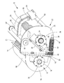
- FIG. 1 shows a perspective view of a grain processor assembly according to the invention.
- a grain processor assembly 10 shown in the figure is provided for detachable installation in a forage harvester, in which it is located in the crop flow between a chopper drum and an ejection accelerator when installed. For this, let the disclosure of the DE 101 28 052 A directed.
- the grain processor assembly 10 comprises a first frame element 12 on which a first roller 14, which is provided with a profiled (eg, sawtooth) surface, is rotatably mounted about the longitudinal axis of the roller 14 by means of a bearing arrangement 16.
- the first frame member 12 comprises a plate 18 extending transversely to the axis of rotation of the roller 14 and a web 20 extending at right angles from the plate 18 away from the roller 14 to which the bearing assembly 16 is secured by screw connections.
- the bridge 20 and the Plate 18 may be welded together or made in one piece (by bending).
- the web 20 is connected by the screw that connect it to the bearing assembly 16 with a parallel to the web 20 extending web 19 which projects at right angles from another plate 21 and with her one piece (by bending) executed or welded.
- a second frame element 22 is provided, on which a second roller 24 equipped with a profiled (eg sawtooth-like) surface is rotatably mounted about the longitudinal axis of the roller 24 by means of a bearing arrangement 26.
- the second frame element 22 comprises a plate 28 extending transversely to the axis of rotation of the roller 14 and a web 30 extending at right angles from the plate 28 and from the roller 24 and welded to the plate 28, to which the bearing assembly 26 is fastened by screw connections.
- the web 30 comprises a lower portion 32 which is angled outwards by about 45 ° relative to the region of the web 30 holding the bearing assembly 26 and extends at least approximately parallel to the web 19 of the first frame member 12.
- the plate 21 covers in the region lying above the web 30 the plate 28 to the outside and extends parallel to it.
- the rollers 14, 24 comprise central shafts 34, 36 which can be set in rotation by means of a respective pulley (not shown) arranged outside the bearing arrangement 16, 26, as a rule with rotational speeds differing by a few percent.
- the rollers 14, 24 pick up the crop in the harvesting operation in the gap remaining between them and close up grains contained in the crop to make them easier to digest.
- a bolt 38 provided with a screw thread extends through a horizontal opening in the web 19 of the further plate 21 of the first frame member 12 and a coaxial opening in the lower portion 32 of the web 30 of the second frame member 22.
- the bolt 38 is located with its head on the web 19 on.
- a ring 40 formed of a plurality of washers is attached to the bolt 38.
- a helical spring, serving as a bracing device 42, spirally surrounding the pin 38 abuts with a first end on the lower portion 32 of the web 30 and with its second end on a washer 46, which in turn is attached to a nut 46 screwed onto the thread of the bolt 38 is applied.
- the nut 46 holds the tensioner 42 in a compressed position so that the latter compresses the frame members 12, 22 until, in the absence or low crop throughput, the ring 40 abuts the web 19 and the lower portion of the web 32.
- a parallel to the longitudinal and rotational axes of the rollers 14, 24 extending shaft 48 extends through an opening in the plate 28 of the second frame member 22 and is rotatably mounted relative to the plate 28, either by a separate roller bearing or only by the direct Contact each other.
- the shaft 48 is rotatably connected at its outer end with an eccentric 50 which is a circular cylindrical member having a relation to the axis of the shaft in the radial direction offset center axis.
- the eccentric 50 is disposed within an opening surrounding it in the further plate 21 of the first frame member 12, so that the latter is rotatable relative to the eccentric 50, either by a separate roller bearing or only by direct contact with each other.
- the shaft 48 is connected via a non-rotatably connected lever 52 and other connecting elements 56 with a power-operated actuator 54 in the form of an electric motor or hydraulic cylinder with a linearly displaceable output element, which is thus suitable to rotate the shaft 48 about its longitudinal axis.
- the housing of the actuator 54 is fixed to the second frame member 22.
- covers 58, 60 with semi-circular cross-sections to the outside to prevent the escape of crop and protect the actuator 54.
- rollers 14, 24 On the rear side with respect to the figure of the rollers 14, 24 further frame elements (not shown) are provided, which are symmetrical to the frame elements 14, 24 shown, the rollers 14, 24 also supported by means not shown bearing arrangements and by another spring (not shown) are biased against each other.
- the local second frame member is also rotatably mounted on the shaft 48, while the local first frame member is rotatably mounted on the shaft 48 via an eccentric 50 '.
- the rollers 14, 24 close between them a gap which is not visible in the drawing and whose size is defined in the absence of Erntegut trimsatz through the ring 40 and the rotational position of the shaft 48. While the pivot bearing with the shaft 48 is on a first (upper) side of the gap, the tensioner 42 is located on the second (lower) side of the gap. As a rule, the second frame element 22 is fastened to the frame of the forage harvester so that the first frame element 12 can rotate clockwise about the eccentric 50 counter to the force of the tensioning device 42 when the crop material enters.
- the tensioning device 42 cooperates with the inlet side of the gap between the rollers 14, 24 relative to the crop flow, while the pivot bearing rests on the outlet side of the gap between the rollers 14, with respect to the crop flow. 24 is located. Accordingly, the gap between the rollers 14, 24 can increase with increasing Erntegut malficient by the first frame member 12 pivots with the first roller 14 relative to the second frame member 22 with the second roller 24 about the central axis of the eccentric 50.
- the shaft 48 can be rotated about its longitudinal axis by means of the actuator 54. This results in a rotation of the eccentric 50 with respect to the first frame member 12 and thus a lateral movement of the first frame member 12 relative to the second frame member 22.
- an operator in the cab of the forage harvester the gap size and thus the effect of the grain processor assembly 10 at adjust the current harvest conditions, especially to the respective crop moisture.
- a detection of the current distance between the rollers 14, 24 or the position of the shaft 48 by means of a suitable sensor is conceivable. It is also an automatic adjustment of the gap size to the harvesting conditions possible, as in the EP 1 166 619 A the disclosure of which is incorporated herein by reference.
Landscapes
- Life Sciences & Earth Sciences (AREA)
- Environmental Sciences (AREA)
- Engineering & Computer Science (AREA)
- Food Science & Technology (AREA)
- Adjustment And Processing Of Grains (AREA)
- Agricultural Machines (AREA)
- Harvesting Machines For Root Crops (AREA)
- Crushing And Grinding (AREA)
- Harvesting Machines For Specific Crops (AREA)
Applications Claiming Priority (1)
| Application Number | Priority Date | Filing Date | Title |
|---|---|---|---|
| DE102008012487A DE102008012487A1 (de) | 2008-03-04 | 2008-03-04 | Körnerprozessorzusammenbau |
Publications (3)
| Publication Number | Publication Date |
|---|---|
| EP2098110A2 true EP2098110A2 (fr) | 2009-09-09 |
| EP2098110A3 EP2098110A3 (fr) | 2009-12-16 |
| EP2098110B1 EP2098110B1 (fr) | 2011-11-23 |
Family
ID=40686828
Family Applications (1)
| Application Number | Title | Priority Date | Filing Date |
|---|---|---|---|
| EP09153576A Active EP2098110B1 (fr) | 2008-03-04 | 2009-02-25 | Assemblage de processeur de grain |
Country Status (5)
| Country | Link |
|---|---|
| US (1) | US7708221B2 (fr) |
| EP (1) | EP2098110B1 (fr) |
| AT (1) | ATE534284T1 (fr) |
| DE (1) | DE102008012487A1 (fr) |
| EA (1) | EA015766B1 (fr) |
Cited By (12)
| Publication number | Priority date | Publication date | Assignee | Title |
|---|---|---|---|---|
| DE102010002343A1 (de) | 2010-02-25 | 2011-08-25 | Deere & Company, Ill. | Feldhäcksler mit einer Häckseleinrichtung und einer stromab der Häckseleinrichtung angeordneten Nachbearbeitungseinrichtung |
| CN107511203A (zh) * | 2016-06-15 | 2017-12-26 | 张荣斌 | 一种双辊式破碎机 |
| DE102016211570A1 (de) | 2016-06-28 | 2017-12-28 | Deere & Company | Antriebsanordnung zum drehzahlveränderbaren Antrieb einer mit zwei Konditionierwalzen ausgestatteten Konditioniereinrichtung eines Feldhäckslers |
| CN109847847A (zh) * | 2019-04-10 | 2019-06-07 | 杭州铭展网络科技有限公司 | 一种碎纸机 |
| CN110420692A (zh) * | 2019-08-13 | 2019-11-08 | 哈尔滨商业大学 | 一种大豆加工用的分级研磨装置 |
| EP3597299A1 (fr) | 2018-07-20 | 2020-01-22 | Bühler AG | Groupe de rouleaux, dispositif de broyage et procédé de réglage de la fente de broyage d'un dispositif de broyage |
| DE102019201116A1 (de) | 2019-01-29 | 2020-07-30 | Deere & Company | Walzenmantel für eine Konditionierwalze |
| BE1027572A1 (de) | 2019-09-30 | 2021-04-06 | Deere & Co | Konditionierwalzenzusammenbau |
| DE102020129795A1 (de) | 2020-08-25 | 2022-03-03 | Deere & Company | Feldhäcksler mit Konditionierwalzen und Verschleißsensor |
| DE102021104994A1 (de) | 2021-03-02 | 2022-09-08 | Deere & Company | Konditionierwalzenzusammenbau |
| BE1029377A1 (de) | 2021-05-28 | 2022-12-01 | Deere & Co | Feldhäcksler mit vorausschauender Ansteuerung des Bearbeitungsgrads eines Körnerprozessors |
| DE102022106264A1 (de) | 2022-03-17 | 2023-09-21 | Deere & Company | Konditionierwalze für eine Konditioniereinrichtung eines Feldhäckslers |
Families Citing this family (11)
| Publication number | Priority date | Publication date | Assignee | Title |
|---|---|---|---|---|
| DE102010002509A1 (de) | 2010-03-02 | 2011-09-08 | Deere & Company | Feldhäcksler mit einer zwischen einer Betriebsposition und einer Außerbetriebsposition bewegbaren Konditioniereinrichtung |
| GB201012281D0 (en) | 2010-07-22 | 2010-09-08 | Agco Int Gmbh | Cracker roller assembly |
| DE202010011422U1 (de) | 2010-08-16 | 2011-06-09 | Zahnradfabrik-Neviges Wolfgang Schmahl GmbH & Co. KG, 42553 | Vorrichtung zur Bearbeitung von Erntegut |
| US9486806B1 (en) | 2011-04-01 | 2016-11-08 | Claas Saulgau Gmbh | System and method for processing crop materials into livestock feed and the product thereof |
| US8991375B2 (en) | 2013-03-15 | 2015-03-31 | Mcp Ip, Llc | Crossbow cabling arrangement |
| DE102013110981A1 (de) * | 2013-10-02 | 2015-04-02 | Thyssenkrupp Industrial Solutions Ag | Verfahren zum Betreiben einer Anlage mit wenigstens einem Aggregat, das eine rotierende Oberfläche aufweist |
| DE102014219049B4 (de) | 2014-09-22 | 2024-07-11 | Deere & Company | Feldhäcksler mit reversierbarer Konditioniereinrichtung |
| US10912255B2 (en) | 2017-05-12 | 2021-02-09 | Deere & Company | Control system for adjusting forming shield of windrowing work vehicle |
| US10806078B2 (en) | 2017-05-12 | 2020-10-20 | Deere & Company | Control system for adjusting conditioning rollers of work vehicle |
| US10813287B2 (en) | 2017-05-12 | 2020-10-27 | Deere & Company | Control system for adjusting swath flap of windrowing work vehicle |
| US11375663B2 (en) | 2019-02-15 | 2022-07-05 | Deere & Company | Ground contour sensing system for crop mowing head |
Citations (5)
| Publication number | Priority date | Publication date | Assignee | Title |
|---|---|---|---|---|
| DE8817251U1 (de) | 1987-10-06 | 1995-12-14 | Bühler AG, Uzwil | Getreidemühle |
| EP1166619A1 (fr) | 2000-06-21 | 2002-01-02 | Deere & Company | Dispositif pour la régulation de la distance et/ou la force de compression entre les rouleaux d'un dispositif après broyage |
| DE10128052A1 (de) | 2001-06-08 | 2002-12-12 | Deere & Co | Halterungszusammenbau einer Gutbearbeitungs und/oder Födereinrichtung |
| DE10235241A1 (de) | 2002-03-14 | 2003-11-13 | Franz Gail | Mahlverfahren und Mühle zum Herstellen von Tierfutter aus Körnerfrüchten |
| EP1600049A1 (fr) | 2004-05-27 | 2005-11-30 | CNH Belgium N.V. | Appareil pour fissurer les grains |
Family Cites Families (13)
| Publication number | Priority date | Publication date | Assignee | Title |
|---|---|---|---|---|
| FR1376499A (fr) * | 1963-03-19 | 1964-10-31 | Perfectionnements au serrage des cylindres de broyeuses et autres machines à cylindres | |
| DD115018A1 (fr) * | 1974-11-11 | 1975-09-12 | ||
| DE2540269B2 (de) * | 1975-09-10 | 1980-12-18 | Kloeckner-Humboldt-Deutz Ag, 5000 Koeln | Einstellbare Stützvorrichtung für die Loswalze einer Walzenmühle |
| US4339083A (en) * | 1976-07-16 | 1982-07-13 | Gebrueder Buehler Ag | Apparatus for the grinding of cereal |
| CH619157A5 (fr) * | 1976-07-16 | 1980-09-15 | Buehler Ag Geb | |
| DE2925126C2 (de) * | 1979-06-22 | 1982-02-11 | Bühler-Miag GmbH, 3300 Braunschweig | Walzwerk für Vermahlungszwecke |
| ATE38626T1 (de) * | 1984-08-03 | 1988-12-15 | Buehler Ag Geb | Mahlspaltverstellvorrichtung fuer muellereiwalzenstuehle. |
| EP0357762B1 (fr) * | 1988-03-10 | 1991-11-27 | Bühler GmbH | Procede et dispositif pour moudre et separer le grain |
| JP2788059B2 (ja) * | 1989-05-22 | 1998-08-20 | 株式会社佐竹製作所 | 製粉用ロール機 |
| DE4216807C2 (de) * | 1992-05-21 | 1996-10-17 | Wirth Muehlenbau Dresden Gmbh | Einrichtung zum berührungslosen Messen des Walzenspaltes eines Walzenpaares |
| IT1275978B1 (it) * | 1995-03-27 | 1997-10-24 | Berga S P A | Macchina a cilindri per la macinazione di cereali e simili con dispositivo a singolo asse di rotazione per la regolazione |
| US6685118B1 (en) * | 2000-12-19 | 2004-02-03 | Robert M. Williams, Jr. | Two roll crusher and method of roller adjustment |
| RU2250136C2 (ru) * | 2002-05-27 | 2005-04-20 | Табакаев Сергей Борисович | Вальцовый станок (варианты) |
-
2008
- 2008-03-04 DE DE102008012487A patent/DE102008012487A1/de not_active Withdrawn
-
2009
- 2009-02-13 EA EA200900189A patent/EA015766B1/ru not_active IP Right Cessation
- 2009-02-25 AT AT09153576T patent/ATE534284T1/de active
- 2009-02-25 EP EP09153576A patent/EP2098110B1/fr active Active
- 2009-02-26 US US12/393,301 patent/US7708221B2/en active Active
Patent Citations (5)
| Publication number | Priority date | Publication date | Assignee | Title |
|---|---|---|---|---|
| DE8817251U1 (de) | 1987-10-06 | 1995-12-14 | Bühler AG, Uzwil | Getreidemühle |
| EP1166619A1 (fr) | 2000-06-21 | 2002-01-02 | Deere & Company | Dispositif pour la régulation de la distance et/ou la force de compression entre les rouleaux d'un dispositif après broyage |
| DE10128052A1 (de) | 2001-06-08 | 2002-12-12 | Deere & Co | Halterungszusammenbau einer Gutbearbeitungs und/oder Födereinrichtung |
| DE10235241A1 (de) | 2002-03-14 | 2003-11-13 | Franz Gail | Mahlverfahren und Mühle zum Herstellen von Tierfutter aus Körnerfrüchten |
| EP1600049A1 (fr) | 2004-05-27 | 2005-11-30 | CNH Belgium N.V. | Appareil pour fissurer les grains |
Cited By (23)
| Publication number | Priority date | Publication date | Assignee | Title |
|---|---|---|---|---|
| EP2361495A1 (fr) | 2010-02-25 | 2011-08-31 | Deere & Company | Ensileuse dotée d'un dispositif de hachage et d'un dispositif de post-traitement agencé en aval du dispositif de hachage |
| US8554424B2 (en) | 2010-02-25 | 2013-10-08 | Deere & Company | Forage harvester with a chopping mechanism and a reworking device located downstream from the chopping mechanism |
| DE102010002343A1 (de) | 2010-02-25 | 2011-08-25 | Deere & Company, Ill. | Feldhäcksler mit einer Häckseleinrichtung und einer stromab der Häckseleinrichtung angeordneten Nachbearbeitungseinrichtung |
| CN107511203A (zh) * | 2016-06-15 | 2017-12-26 | 张荣斌 | 一种双辊式破碎机 |
| DE102016211570A1 (de) | 2016-06-28 | 2017-12-28 | Deere & Company | Antriebsanordnung zum drehzahlveränderbaren Antrieb einer mit zwei Konditionierwalzen ausgestatteten Konditioniereinrichtung eines Feldhäckslers |
| DE102016211570B4 (de) * | 2016-06-28 | 2025-05-15 | Deere & Company | Antriebsanordnung zum drehzahlveränderbaren Antrieb einer mit zwei Konditionierwalzen ausgestatteten Konditioniereinrichtung eines Feldhäckslers |
| EP3597299A1 (fr) | 2018-07-20 | 2020-01-22 | Bühler AG | Groupe de rouleaux, dispositif de broyage et procédé de réglage de la fente de broyage d'un dispositif de broyage |
| WO2020016060A1 (fr) | 2018-07-20 | 2020-01-23 | Bühler AG | Groupe de cylindres, dispositif de broyage et procédé de réglage de la fente de broyage d'un dispositif de broyage |
| EP3689130A1 (fr) | 2019-01-29 | 2020-08-05 | Deere & Company | Enveloppe de rouleau pour un rouleau de conditionnement |
| DE102019201116A1 (de) | 2019-01-29 | 2020-07-30 | Deere & Company | Walzenmantel für eine Konditionierwalze |
| CN109847847A (zh) * | 2019-04-10 | 2019-06-07 | 杭州铭展网络科技有限公司 | 一种碎纸机 |
| CN110420692A (zh) * | 2019-08-13 | 2019-11-08 | 哈尔滨商业大学 | 一种大豆加工用的分级研磨装置 |
| BE1027572A1 (de) | 2019-09-30 | 2021-04-06 | Deere & Co | Konditionierwalzenzusammenbau |
| BE1027572B1 (de) * | 2019-09-30 | 2021-07-12 | Deere & Co | Konditionierwalzenzusammenbau |
| US11825769B2 (en) | 2019-09-30 | 2023-11-28 | Deere & Company | Conditioning roller assembly |
| DE102020129795A1 (de) | 2020-08-25 | 2022-03-03 | Deere & Company | Feldhäcksler mit Konditionierwalzen und Verschleißsensor |
| DE102021104994A1 (de) | 2021-03-02 | 2022-09-08 | Deere & Company | Konditionierwalzenzusammenbau |
| BE1029114A1 (de) | 2021-03-02 | 2022-09-08 | Deere & Co | Konditionierwalzenzusammenbau |
| BE1029114B1 (de) * | 2021-03-02 | 2022-12-16 | Deere & Co | Konditionierwalzenzusammenbau |
| US12239050B2 (en) | 2021-03-02 | 2025-03-04 | Deere & Company | Conditioning roller assembly pivotable to open position for servicing |
| BE1029377A1 (de) | 2021-05-28 | 2022-12-01 | Deere & Co | Feldhäcksler mit vorausschauender Ansteuerung des Bearbeitungsgrads eines Körnerprozessors |
| DE102021113838A1 (de) | 2021-05-28 | 2022-12-01 | Deere & Company | Feldhäcksler mit vorausschauender Ansteuerung des Bearbeitungsgrads eines Körnerprozessors |
| DE102022106264A1 (de) | 2022-03-17 | 2023-09-21 | Deere & Company | Konditionierwalze für eine Konditioniereinrichtung eines Feldhäckslers |
Also Published As
| Publication number | Publication date |
|---|---|
| DE102008012487A1 (de) | 2009-09-10 |
| ATE534284T1 (de) | 2011-12-15 |
| EP2098110A3 (fr) | 2009-12-16 |
| EP2098110B1 (fr) | 2011-11-23 |
| EA200900189A1 (ru) | 2009-10-30 |
| US20090223192A1 (en) | 2009-09-10 |
| EA015766B1 (ru) | 2011-12-30 |
| US7708221B2 (en) | 2010-05-04 |
Similar Documents
| Publication | Publication Date | Title |
|---|---|---|
| EP2098110B1 (fr) | Assemblage de processeur de grain | |
| EP0598705B1 (fr) | Dispositif de broyage et/ou compactage de composants d'aliments ou de fourrage | |
| DE602004004500T2 (de) | Gewächsbearbeitungsvorrichtung | |
| DE102014219049B4 (de) | Feldhäcksler mit reversierbarer Konditioniereinrichtung | |
| DE102007009587A1 (de) | Vorrichtung zur Einstellung der Position des Nachbeschleunigungsorgans in einer landwirtschaftlichen Erntemaschine | |
| EP2910105B1 (fr) | Protection contre les surcharges de lame de coupe | |
| BE1027572B1 (de) | Konditionierwalzenzusammenbau | |
| EP1932419B1 (fr) | Presse agricole | |
| EP1621064B1 (fr) | Conveyeur-élévateur pour une machine agricole | |
| EP3354126B1 (fr) | Couteau et tambour de hachoir pour une ramasseuse-hacheuse | |
| EP1927278A1 (fr) | Dispositif de guidage de marchandise dans un appareil agricole | |
| DE19538199C2 (de) | Feldhäcksler mit Konditioniereinrichtung | |
| EP0654434A1 (fr) | Dispositif de pressage pour des articles imprimés pliés tels que journaux, magazines et des parties de ceux-ci | |
| DE3213199C1 (de) | Ladewagen | |
| EP0153621B1 (fr) | Hacheuse à tambour avec une broyeuse secondaire | |
| DE4418696C2 (de) | Walzenkonditioniermaschine | |
| EP4074162B1 (fr) | Presse à balles rondes pourvue de rouleau de démarrage et d'élément de déviation pouvant être dévié élastiquement | |
| DE102021105149A1 (de) | Verstellbare Winkelausrichtung einer frei mitlaufenden Riemenscheibe eines Riementriebs | |
| EP2910104B1 (fr) | Dispositif de coupe pour une moissonneuse | |
| DE3539909A1 (de) | Feldhaecksler | |
| EP4039080B1 (fr) | Presse a balles | |
| BE1029114B1 (de) | Konditionierwalzenzusammenbau | |
| DE2719266C2 (de) | Schlägermühle | |
| EP2415341B1 (fr) | Entraînement pour un dispositif de surcharge d'une moissonneuse agricole | |
| DE29504826U1 (de) | Häcksler |
Legal Events
| Date | Code | Title | Description |
|---|---|---|---|
| PUAI | Public reference made under article 153(3) epc to a published international application that has entered the european phase |
Free format text: ORIGINAL CODE: 0009012 |
|
| AK | Designated contracting states |
Kind code of ref document: A2 Designated state(s): AT BE BG CH CY CZ DE DK EE ES FI FR GB GR HR HU IE IS IT LI LT LU LV MC MK MT NL NO PL PT RO SE SI SK TR |
|
| AX | Request for extension of the european patent |
Extension state: AL BA RS |
|
| PUAL | Search report despatched |
Free format text: ORIGINAL CODE: 0009013 |
|
| AK | Designated contracting states |
Kind code of ref document: A3 Designated state(s): AT BE BG CH CY CZ DE DK EE ES FI FR GB GR HR HU IE IS IT LI LT LU LV MC MK MT NL NO PL PT RO SE SI SK TR |
|
| AX | Request for extension of the european patent |
Extension state: AL BA RS |
|
| 17P | Request for examination filed |
Effective date: 20100616 |
|
| 17Q | First examination report despatched |
Effective date: 20100727 |
|
| AKX | Designation fees paid |
Designated state(s): AT BE BG CH CY CZ DE DK EE ES FI FR GB GR HR HU IE IS IT LI LT LU LV MC MK MT NL NO PL PT RO SE SI SK TR |
|
| GRAP | Despatch of communication of intention to grant a patent |
Free format text: ORIGINAL CODE: EPIDOSNIGR1 |
|
| GRAS | Grant fee paid |
Free format text: ORIGINAL CODE: EPIDOSNIGR3 |
|
| GRAA | (expected) grant |
Free format text: ORIGINAL CODE: 0009210 |
|
| AK | Designated contracting states |
Kind code of ref document: B1 Designated state(s): AT BE BG CH CY CZ DE DK EE ES FI FR GB GR HR HU IE IS IT LI LT LU LV MC MK MT NL NO PL PT RO SE SI SK TR |
|
| REG | Reference to a national code |
Ref country code: GB Ref legal event code: FG4D Free format text: NOT ENGLISH |
|
| REG | Reference to a national code |
Ref country code: CH Ref legal event code: EP |
|
| REG | Reference to a national code |
Ref country code: IE Ref legal event code: FG4D Free format text: LANGUAGE OF EP DOCUMENT: GERMAN |
|
| REG | Reference to a national code |
Ref country code: DE Ref legal event code: R096 Ref document number: 502009001988 Country of ref document: DE Effective date: 20120202 |
|
| REG | Reference to a national code |
Ref country code: NL Ref legal event code: VDEP Effective date: 20111123 |
|
| LTIE | Lt: invalidation of european patent or patent extension |
Effective date: 20111123 |
|
| PG25 | Lapsed in a contracting state [announced via postgrant information from national office to epo] |
Ref country code: LT Free format text: LAPSE BECAUSE OF FAILURE TO SUBMIT A TRANSLATION OF THE DESCRIPTION OR TO PAY THE FEE WITHIN THE PRESCRIBED TIME-LIMIT Effective date: 20111123 Ref country code: IS Free format text: LAPSE BECAUSE OF FAILURE TO SUBMIT A TRANSLATION OF THE DESCRIPTION OR TO PAY THE FEE WITHIN THE PRESCRIBED TIME-LIMIT Effective date: 20120323 Ref country code: NO Free format text: LAPSE BECAUSE OF FAILURE TO SUBMIT A TRANSLATION OF THE DESCRIPTION OR TO PAY THE FEE WITHIN THE PRESCRIBED TIME-LIMIT Effective date: 20120223 |
|
| PG25 | Lapsed in a contracting state [announced via postgrant information from national office to epo] |
Ref country code: GR Free format text: LAPSE BECAUSE OF FAILURE TO SUBMIT A TRANSLATION OF THE DESCRIPTION OR TO PAY THE FEE WITHIN THE PRESCRIBED TIME-LIMIT Effective date: 20120224 Ref country code: PT Free format text: LAPSE BECAUSE OF FAILURE TO SUBMIT A TRANSLATION OF THE DESCRIPTION OR TO PAY THE FEE WITHIN THE PRESCRIBED TIME-LIMIT Effective date: 20120323 Ref country code: LV Free format text: LAPSE BECAUSE OF FAILURE TO SUBMIT A TRANSLATION OF THE DESCRIPTION OR TO PAY THE FEE WITHIN THE PRESCRIBED TIME-LIMIT Effective date: 20111123 Ref country code: SE Free format text: LAPSE BECAUSE OF FAILURE TO SUBMIT A TRANSLATION OF THE DESCRIPTION OR TO PAY THE FEE WITHIN THE PRESCRIBED TIME-LIMIT Effective date: 20111123 Ref country code: HR Free format text: LAPSE BECAUSE OF FAILURE TO SUBMIT A TRANSLATION OF THE DESCRIPTION OR TO PAY THE FEE WITHIN THE PRESCRIBED TIME-LIMIT Effective date: 20111123 Ref country code: NL Free format text: LAPSE BECAUSE OF FAILURE TO SUBMIT A TRANSLATION OF THE DESCRIPTION OR TO PAY THE FEE WITHIN THE PRESCRIBED TIME-LIMIT Effective date: 20111123 Ref country code: SI Free format text: LAPSE BECAUSE OF FAILURE TO SUBMIT A TRANSLATION OF THE DESCRIPTION OR TO PAY THE FEE WITHIN THE PRESCRIBED TIME-LIMIT Effective date: 20111123 |
|
| REG | Reference to a national code |
Ref country code: IE Ref legal event code: FD4D |
|
| PG25 | Lapsed in a contracting state [announced via postgrant information from national office to epo] |
Ref country code: CY Free format text: LAPSE BECAUSE OF FAILURE TO SUBMIT A TRANSLATION OF THE DESCRIPTION OR TO PAY THE FEE WITHIN THE PRESCRIBED TIME-LIMIT Effective date: 20111123 |
|
| PG25 | Lapsed in a contracting state [announced via postgrant information from national office to epo] |
Ref country code: DK Free format text: LAPSE BECAUSE OF FAILURE TO SUBMIT A TRANSLATION OF THE DESCRIPTION OR TO PAY THE FEE WITHIN THE PRESCRIBED TIME-LIMIT Effective date: 20111123 Ref country code: BG Free format text: LAPSE BECAUSE OF FAILURE TO SUBMIT A TRANSLATION OF THE DESCRIPTION OR TO PAY THE FEE WITHIN THE PRESCRIBED TIME-LIMIT Effective date: 20120223 Ref country code: EE Free format text: LAPSE BECAUSE OF FAILURE TO SUBMIT A TRANSLATION OF THE DESCRIPTION OR TO PAY THE FEE WITHIN THE PRESCRIBED TIME-LIMIT Effective date: 20111123 Ref country code: CZ Free format text: LAPSE BECAUSE OF FAILURE TO SUBMIT A TRANSLATION OF THE DESCRIPTION OR TO PAY THE FEE WITHIN THE PRESCRIBED TIME-LIMIT Effective date: 20111123 Ref country code: IE Free format text: LAPSE BECAUSE OF FAILURE TO SUBMIT A TRANSLATION OF THE DESCRIPTION OR TO PAY THE FEE WITHIN THE PRESCRIBED TIME-LIMIT Effective date: 20111123 Ref country code: SK Free format text: LAPSE BECAUSE OF FAILURE TO SUBMIT A TRANSLATION OF THE DESCRIPTION OR TO PAY THE FEE WITHIN THE PRESCRIBED TIME-LIMIT Effective date: 20111123 |
|
| PG25 | Lapsed in a contracting state [announced via postgrant information from national office to epo] |
Ref country code: PL Free format text: LAPSE BECAUSE OF FAILURE TO SUBMIT A TRANSLATION OF THE DESCRIPTION OR TO PAY THE FEE WITHIN THE PRESCRIBED TIME-LIMIT Effective date: 20111123 Ref country code: RO Free format text: LAPSE BECAUSE OF FAILURE TO SUBMIT A TRANSLATION OF THE DESCRIPTION OR TO PAY THE FEE WITHIN THE PRESCRIBED TIME-LIMIT Effective date: 20111123 Ref country code: IT Free format text: LAPSE BECAUSE OF FAILURE TO SUBMIT A TRANSLATION OF THE DESCRIPTION OR TO PAY THE FEE WITHIN THE PRESCRIBED TIME-LIMIT Effective date: 20111123 |
|
| PG25 | Lapsed in a contracting state [announced via postgrant information from national office to epo] |
Ref country code: MC Free format text: LAPSE BECAUSE OF NON-PAYMENT OF DUE FEES Effective date: 20120229 |
|
| PLBE | No opposition filed within time limit |
Free format text: ORIGINAL CODE: 0009261 |
|
| STAA | Information on the status of an ep patent application or granted ep patent |
Free format text: STATUS: NO OPPOSITION FILED WITHIN TIME LIMIT |
|
| 26N | No opposition filed |
Effective date: 20120824 |
|
| REG | Reference to a national code |
Ref country code: DE Ref legal event code: R097 Ref document number: 502009001988 Country of ref document: DE Effective date: 20120824 |
|
| PG25 | Lapsed in a contracting state [announced via postgrant information from national office to epo] |
Ref country code: MK Free format text: LAPSE BECAUSE OF FAILURE TO SUBMIT A TRANSLATION OF THE DESCRIPTION OR TO PAY THE FEE WITHIN THE PRESCRIBED TIME-LIMIT Effective date: 20111123 |
|
| PG25 | Lapsed in a contracting state [announced via postgrant information from national office to epo] |
Ref country code: ES Free format text: LAPSE BECAUSE OF FAILURE TO SUBMIT A TRANSLATION OF THE DESCRIPTION OR TO PAY THE FEE WITHIN THE PRESCRIBED TIME-LIMIT Effective date: 20120305 |
|
| PG25 | Lapsed in a contracting state [announced via postgrant information from national office to epo] |
Ref country code: FI Free format text: LAPSE BECAUSE OF FAILURE TO SUBMIT A TRANSLATION OF THE DESCRIPTION OR TO PAY THE FEE WITHIN THE PRESCRIBED TIME-LIMIT Effective date: 20111123 |
|
| PG25 | Lapsed in a contracting state [announced via postgrant information from national office to epo] |
Ref country code: MT Free format text: LAPSE BECAUSE OF FAILURE TO SUBMIT A TRANSLATION OF THE DESCRIPTION OR TO PAY THE FEE WITHIN THE PRESCRIBED TIME-LIMIT Effective date: 20111123 |
|
| REG | Reference to a national code |
Ref country code: CH Ref legal event code: PL |
|
| GBPC | Gb: european patent ceased through non-payment of renewal fee |
Effective date: 20130225 |
|
| PG25 | Lapsed in a contracting state [announced via postgrant information from national office to epo] |
Ref country code: LI Free format text: LAPSE BECAUSE OF NON-PAYMENT OF DUE FEES Effective date: 20130228 Ref country code: CH Free format text: LAPSE BECAUSE OF NON-PAYMENT OF DUE FEES Effective date: 20130228 |
|
| PG25 | Lapsed in a contracting state [announced via postgrant information from national office to epo] |
Ref country code: GB Free format text: LAPSE BECAUSE OF NON-PAYMENT OF DUE FEES Effective date: 20130225 |
|
| PG25 | Lapsed in a contracting state [announced via postgrant information from national office to epo] |
Ref country code: TR Free format text: LAPSE BECAUSE OF FAILURE TO SUBMIT A TRANSLATION OF THE DESCRIPTION OR TO PAY THE FEE WITHIN THE PRESCRIBED TIME-LIMIT Effective date: 20111123 |
|
| PG25 | Lapsed in a contracting state [announced via postgrant information from national office to epo] |
Ref country code: LU Free format text: LAPSE BECAUSE OF NON-PAYMENT OF DUE FEES Effective date: 20120225 |
|
| PG25 | Lapsed in a contracting state [announced via postgrant information from national office to epo] |
Ref country code: HU Free format text: LAPSE BECAUSE OF FAILURE TO SUBMIT A TRANSLATION OF THE DESCRIPTION OR TO PAY THE FEE WITHIN THE PRESCRIBED TIME-LIMIT Effective date: 20090225 |
|
| REG | Reference to a national code |
Ref country code: AT Ref legal event code: MM01 Ref document number: 534284 Country of ref document: AT Kind code of ref document: T Effective date: 20140225 |
|
| PG25 | Lapsed in a contracting state [announced via postgrant information from national office to epo] |
Ref country code: AT Free format text: LAPSE BECAUSE OF NON-PAYMENT OF DUE FEES Effective date: 20140225 |
|
| REG | Reference to a national code |
Ref country code: FR Ref legal event code: PLFP Year of fee payment: 8 |
|
| REG | Reference to a national code |
Ref country code: FR Ref legal event code: PLFP Year of fee payment: 9 |
|
| REG | Reference to a national code |
Ref country code: FR Ref legal event code: PLFP Year of fee payment: 10 |
|
| REG | Reference to a national code |
Ref country code: DE Ref legal event code: R084 Ref document number: 502009001988 Country of ref document: DE |
|
| PGFP | Annual fee paid to national office [announced via postgrant information from national office to epo] |
Ref country code: DE Payment date: 20260121 Year of fee payment: 18 |
|
| PGFP | Annual fee paid to national office [announced via postgrant information from national office to epo] |
Ref country code: BE Payment date: 20260227 Year of fee payment: 18 |
|
| PGFP | Annual fee paid to national office [announced via postgrant information from national office to epo] |
Ref country code: FR Payment date: 20260225 Year of fee payment: 18 |