EP2910104B1 - Dispositif de coupe pour une moissonneuse - Google Patents
Dispositif de coupe pour une moissonneuse Download PDFInfo
- Publication number
- EP2910104B1 EP2910104B1 EP15154944.1A EP15154944A EP2910104B1 EP 2910104 B1 EP2910104 B1 EP 2910104B1 EP 15154944 A EP15154944 A EP 15154944A EP 2910104 B1 EP2910104 B1 EP 2910104B1
- Authority
- EP
- European Patent Office
- Prior art keywords
- cutting
- lever
- axis
- conveyor drum
- connecting element
- Prior art date
- Legal status (The legal status is an assumption and is not a legal conclusion. Google has not performed a legal analysis and makes no representation as to the accuracy of the status listed.)
- Active
Links
Images

Classifications
-
- A—HUMAN NECESSITIES
- A01—AGRICULTURE; FORESTRY; ANIMAL HUSBANDRY; HUNTING; TRAPPING; FISHING
- A01D—HARVESTING; MOWING
- A01D90/00—Vehicles for carrying harvested crops with means for selfloading or unloading
- A01D90/02—Loading means
- A01D90/04—Loading means with additional cutting means
-
- A—HUMAN NECESSITIES
- A01—AGRICULTURE; FORESTRY; ANIMAL HUSBANDRY; HUNTING; TRAPPING; FISHING
- A01F—PROCESSING OF HARVESTED PRODUCE; HAY OR STRAW PRESSES; DEVICES FOR STORING AGRICULTURAL OR HORTICULTURAL PRODUCE
- A01F15/00—Baling presses for straw, hay or the like
- A01F15/08—Details
- A01F15/10—Feeding devices for the crop material e.g. precompression devices
Definitions
- the invention relates to a trained according to the preamble of claim 1 cutting for a harvester such as in particular a self-loading wagon or a baler.
- the biasing means for each of the cutting blades on a support and switching member which allows a switching position, a resilient support of the respective cutting blade in the cutting position.
- the support and switching elements are rotatably mounted on a common shift shaft and each biased by a torsion spring in a support position for supporting in the cutting position of the respective cutting blade.
- the respective support and switching element abuts against a rear side of the associated cutting blade and thus supports it in the cutting position yielding. Due to the arrangement relationship of support and switching element and associated cutting blade only a small lever arm is effective in the cutting position of the respective cutting blade, which causes a large biasing force. When yielding from the cutting position out pivoting the respective cutting blade, however, this lever arm increases increasingly, causing a reduction of the biasing force.
- DE 10 2011 013 640 A1 discloses a cutting unit for a harvesting machine with at least one knife mounted on a knife carrier and held projecting in a cutting position in a Erntegutkanal, the knife carrier between a working position and a non-working position, in which the at least one knife is arranged outside the Erntegutkanals , is movably mounted, wherein the at least one knife is movably mounted on the knife carrier such that the knife is in its working position befindlichem knife carrier from its cutting position in an evasive and / or non-cutting position can be brought, the knife a prestressable return device for resetting the knife is assigned from the alternate and / or non-cutting position in the cutting position, wherein the knife retaining means for retaining the knife are assigned in its avoidance and / or non-cutting position relative to the knife carrier and the return device deactivating ngsmittel are assigned for switching off or reducing the restoring force.
- Out DE 36 03 667 A1 is a cutting device in the conveyor channel of agricultural machines known with a variety in working position in the delivery channel protruding, at a location outside of the conveyor channel pivot individually mounted knives, articulated by a swivel arm articulated on the back of the knife with its free end spring-loaded toggle lever system with a frame-mounted support arm are guided so that they can avoid overloading against the spring force, the one hand fixed to the frame fixed spring acts on the support arm and one of the arms on the side facing away from the blade on the knee joint protruding continuation and on this is provided an adjustable and lockable stop for the other arm, through which the opening angle of the toggle lever system is adjustable.
- a cutting unit for a harvesting machine such as in particular a loading wagon or a baler, comprises: a conveyor drum which is rotatably mounted about an axis of rotation extending in a longitudinal direction thereof; a plurality of cutting blades, which can be pivoted about a pivot axis from a cutting position in which the cutting blades are placed in a conveyor channel for crop formed on the conveyor drum, each in a pivoting direction away from the conveyor drum; and Biasing means arranged to provide, for each of the cutting blades, a biasing force biasing the respective cutting blade in a pivoting direction toward the cutting position, and arranged to change a magnitude of the biasing force, in particular while maintaining a position of the pivotal axis of the cutting blades.
- the cutting mechanism according to the invention is characterized in that the biasing means comprise force adjusting means arranged such that the magnitude of the biasing force is variable, i. in a predetermined adjustment range and in particular independently of a deflection of the cutting blade and any other condition freely selectable, is adjustable.
- the magnitude of the variable force biasing force is simultaneously and uniformly adjustable for all the cutting blades of the plurality of cutting blades.
- the conveyor drum around an outer circumference and distributed in the longitudinal direction of a plurality of radially outwardly projecting conveying elements and the cutting blades are arranged side by side in the longitudinal direction of the conveyor drum with respective spacing, wherein the cutting blades each extend around the preferably parallel to the axis of rotation of the conveyor drum Pivot axis are pivotally mounted, that each cutting blade from the cutting position in which it is set into the conveyor channel formed on the conveyor drum for crop to cut the crop in cooperation with the conveyor elements, in the event of a collision with a foreign body in the conveyor channel against the biasing force in the direction away from the conveyor drum can swerve.
- the biasing force is generated by the cooperation of the spring action of the spring means with a lever action of the lever mechanism. Since two components realize the acting preload force here, the preload force can be varied even better and thus be even better adapted to the conditions of use.
- the biasing means by suitably tuning of lever mechanism (Hebelarminaten) and spring means (strength of the spring action) can be better adapted to the available space.
- the spring means comprise for each lever mechanism a separate spring, one end of which is connected at a point of articulation with the respective lever mechanism, the force adjusting means comprising a connecting element interconnecting respective other ends of the springs of the lever mechanisms and spacing adjusting means , Which are arranged so that a distance of the connecting element of the respective articulation points is variable and adjustable for all springs simultaneously and uniformly.
- the connecting element has two longitudinal ends opposite in the longitudinal direction of the conveyor drum, wherein the drive device comprises two piston-cylinder units, which are connected to one of the longitudinal ends of the connecting element and arranged so that a linear displacement movement of each piston Cylinder unit is transferable to the connecting element, and wherein the two piston-cylinder units are synchronized with each other.
- the piston-cylinder units are in each case connected to one end (piston rod or cylinder) with one of the longitudinal ends of the connecting element and movably connected to the other end (cylinder or piston rod) with a fixed element such as a housing of the cutting unit or thereto supported.
- Hydraulic piston-cylinder units can be integrated in a simple manner in the hydraulics of a harvester and thus reduce the driving effort for the cutting unit adjustment.
- the drive means could include other motors such as linear motors (e.g., spindle drive) or rotary motors (e.g., servomotors) for driving the pivotal movement of the connector.
- the lever mechanisms of the biasing means are each formed as a toggle mechanism, which two Knee lever, which are connected via an articulated joint at respective longitudinal ends of this one extending in the longitudinal direction of the conveyor drum first toggle lever axis, wherein the articulated joint in an extended position of the toggle, in which the toggle at the articulated joint at an angle of only slightly less than 180 degrees with each other include or run almost in a straight line, is adjustable to stop, so that the support position for the respective cutting blade is made.
- a longitudinal end remote from the articulated joint of a toggle lever is pivotally mounted about a second toggle lever axis parallel to the first toggle lever axis and a longitudinal end of the other toggle lever is pivotally connected to the cutting blade about a third toggle lever axis parallel to the first toggle lever axis that in the pivoting direction away from the conveying drum pivoting of the cutting blade causes a buckling of the toggle lever of the toggle mechanism against the bias of the spring means from the extended position in the articulated joint.
- the force adjusting means comprise adjustment detecting means arranged to detect a setting parameter of the force adjusting means related to the magnitude of the biasing force.
- the adjustment detecting means may be e.g. an angle sensor for detecting a pivoting angle of one or both of the pivot levers of the distance adjustment means and / or a linear displacement sensor such as a distance measuring cylinder for detecting a linear displacement of one or both of the piston-cylinder units of the drive means of the distance adjustment means.
- the cutting mechanism has a swivel-out detection device which is set up to detect when one of the cutting knives is swung out of its cutting position.
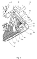
- FIGS. 1 and 2 show a cutting unit 10 of a harvester 1 (not fully shown) according to an embodiment of the invention.
- the harvester 1 is preferably designed as a loader wagon or baler, wherein the cutting unit 10 is a pickup device (not shown) with eg a spiked roller for receiving not shown crop (such as grass or other stalk and / or Blattgut) is preceded by an agricultural field ,
- the picked up by the pickup device or receiving device crop is then promoted by this rotationally to an input 11a of a conveyor channel 11 of the cutting unit 10 and taken there by a conveyor drum 20 of the cutting unit 10 and further conveyed along the conveyor channel 11 for cutting. After cutting the crop, this is output at an output 11 b from the conveyor channel 11 and there, for example. from a pressing device or another conveyor (both latter not shown) taken.
- the cutter 10 has the conveyor drum 20, a housing 30, a plurality of cutting blades 40 and biasing means 50 for the cutting blades 40.
- the conveying drum 20 is rotated about one in a longitudinal direction of this (y-axis direction in FIG Fig. 1 ) extending axis of rotation A1 rotatably mounted on the housing 30 and has an outer periphery 21 of the conveyor drum 20 and in the The longitudinal direction distributes a plurality of radially outwardly projecting conveying elements in the form of driver tines 24, which together define an enveloping cylinder 26 of the conveyor drum 20.
- a guide element 31 of the housing 30 is formed as a bottom plate of the cutting unit 10 and shields a cutter mechanism (not separately referred to) received in the housing 30 against the conveyor channel 11.
- the guide element 31 extends in the longitudinal direction of the conveyor drum 20 over an entire length of the enveloping cylinder 26 and arcuately about a sector of an outer circumference of the enveloping cylinder 26 that between the outer periphery 21 of the conveyor drum 20 and the guide element 31 of the conveyor channel 11 is formed for the crop ,
- the cutting blades 40 are longitudinally (y-axis direction in FIG Fig. 1 ) of the conveyor drum 20 are arranged at a respective distance from each other side by side in a row, so that they cover the entire working length of the conveyor drum 20 or use.
- Each cutting blade 40 has a first longitudinal end 41 a and a second longitudinal end 41 b and extends in an in Fig. 1 shown cutting position with its second longitudinal end 41 b mounted on a housing 30 on a side facing away from the conveyor drum 20 side of the guide element 31 pivot axis A2 stored from the side facing away from the conveyor drum 20 side of the guide element 31 from alongside through a slot-shaped opening 32 in the guide element 31 passes into the conveying channel 11 and engages in the distance between two adjacent Mitêtinparen to cut in cooperation with the Mit recruitingzinken (conveyor elements) 24 through the conveying channel 11 conveyed through crop.
- the first longitudinal end 41 a projects into the delivery channel 11.
- the cutting blades 40 each have, as reversible cutting blades formed on their opposite longitudinal sides respective cutting edges 43a and 43b, which are mirror-symmetrical along their length dimension concavely curved.
- the cutting blades 40 are individually supported via respective blade receivers 45 between the cutting position, in which they are biased by the biasing means 50 by means of a biasing force acting in a pivoting direction to the cutting position, a deflection position and an inoperative position pivotally mounted on the pivot axis A2.
- each cutting blade 40 is pivotally mounted at its second longitudinal end 41 b via its respective blade holder 45 in the longitudinal direction (y-axis direction) or parallel to the axis of rotation A1 of the conveyor drum 20 extending pivot axis A2, so that the cutting blade 40 from the in Fig. 1 shown cutting position, in which it is set into the conveyor channel 11, in collision with a foreign body in the conveyor channel 11 against the preload provided by the biasing means 50 biasing force through the associated opening 32 in the guide element 31 in the pivoting direction away from the conveyor drum 20 in the evasive position can dodge or can be pivoted when not in use further into the inoperative position.
- the lever mechanism 60 is connected to the respective cutting blade 40 and abutment in one in the FIGS. 1 and 2 shown support position adjustable, in which the respective cutting blade 40 is in the cutting position.
- the spring means 70 bias the lever mechanisms 60 by spring action towards the stop in the support position, so that the respectively desired biasing force is provided in the pivoting direction of the cutting blade 40 to the cutting position for the respective cutting blade 40.
- the lever mechanisms 60 are each designed as a toggle mechanism, which has two toggle levers 61, 62, which are pivotally connected to one another via an articulated joint 63 at respective longitudinal ends of this around a parallel to the axis of rotation A1 of the conveyor drum 20 extending first toggle lever axis A3, wherein the articulated joint 63 in an extended position of the toggle lever 61, 62, in which the toggle 61, 62 at the articulated joint 63 at an angle of only a little less than 180 degrees with each other or almost straight line, stop is adjustable, so that in the FIGS. 1 and 2 shown supporting position for the respective cutting blade 40 is made.
- the spring means 70 have for each lever mechanism 60, a separate tension spring 71 made of metal, one end of which is connected at a pivot point 64 with the respective lever mechanism 60, so that the tension spring 71 their spring force or spring action on the articulated joint 63 in the respective lever mechanism 60th Initially this biases to the stop of the articulated joint 63 in the extended position.
- a pivoting in the pivoting direction away from the conveyor drum 20 of a respective cutting blade 40 causes a from the extended position in the articulated joint 63 buckling of the toggle lever 61, 62 of the lever mechanism 60 against the spring force of the tension spring 71st
- the force adjustment means 80 are provided according to the invention so that a strength of the spring action and a magnitude of the spring force is variable and for all lever mechanisms 60 of the cutting blade 40 simultaneously and uniformly adjustable.
- the force adjusting means 80 comprise a carrier-like connecting member 81 connecting respective other ends of the tension springs 71 of the lever mechanisms 60 and pitch adjusting means 85 arranged such that a distance of the connecting member 81 from the respective pivot points 64 becomes variable and for all the tension springs 71 simultaneously and is uniformly adjustable.
- the distance adjusting means 85 point longitudinally (in the y-axis direction in FIG Fig. 1 ) of the conveyor drum 20 spaced pivoting lever 86, which are each mounted on the longitudinal axis of the conveyor drum or parallel to the axis of rotation A1 extending pivot axis A6 pivotally mounted on the housing 30 and which are connected to the connecting element 81, so that the connecting element 81 on the Pivoting lever 86 a pivoting movement about its pivot axis A6 to the pivot points 64 toward and away from them can perform.
- the distance adjustment means 85 For driving the pivoting movement of the connecting element 81, the distance adjustment means 85 have a drive device 87.
- the connecting element 81 has two longitudinally (in the y-axis direction in Fig. 1 ) of the conveyor drum 20 opposite longitudinal ends (in Fig. 2 only one longitudinal end 81a can be seen), wherein the drive means 87 comprises two movement-synchronized hydraulic piston-cylinder units 88 (in Fig. 2 only one piston-cylinder unit 88 can be seen), which are each connected to one of the longitudinal ends 81 a of the connecting element 81 and arranged so that a linear adjustment movement of each piston-cylinder unit 88 to the connecting element 81 is transferable.
- each piston-cylinder unit 88 is pivotally connected to one of the longitudinal ends 81 a of the connecting member 81 and a cylinder-side end of each piston-cylinder unit 88 is pivotally connected to the housing 30 of the cutting unit 10 and supported thereon.
- the force adjusting means 80 further includes adjustment detecting means arranged to detect a setting parameter of the force adjusting means 80 related to the magnitude of the biasing force for the cutting blades 40.
- the cutting unit 10 also has a pivoting detection device which is adapted to detect when one of the cutting blades 40 is pivoted out of its cutting position.
- the Ausschwenk-detection device has for this purpose a light barrier 95, so that can be detected when one of the cutting blade 40 is pivoted out of its cutting position. From this it can be advantageous, e.g. infer the number of blade deflections per unit of time, which may be a parameter for the adjustment of the biasing force.
- the desired biasing force for the cutting blades 40 can be variable in a control terminal (not shown) and for all cutting blades 40 be set simultaneously and uniformly.
- the optimal Ausgurschwelle for the cutting blade 40 can be adjusted.
- the Ausschwenk detection device (light barrier 95) can be used in addition to detecting the number of blade deflections or knife triggering. Thus, e.g. when exceeding a certain number of blade deflections per unit time, the biasing force can be increased and / or falls below a certain number of blade deflections per unit time, the biasing force can be reduced.
Landscapes
- Life Sciences & Earth Sciences (AREA)
- Environmental Sciences (AREA)
- Harvester Elements (AREA)
Claims (8)
- Tablier de coupe (10) pour une machine de récolte (1), présentant un tambour d'alimentation (20) qui est monté rotatif autour d'un axe de rotation (A1) s'étendant dans une direction longitudinale de celui-ci, une pluralité de couteaux (40) qui peuvent chacun pivoter autour d'un axe de pivotement (A2) à partir d'une position de coupe, où les couteaux (40) sont placés dans un canal d'alimentation (11) pour produit de récolte formé sur le tambour d'alimentation (20), dans un sens de pivotement qui les éloigne du tambour d'alimentation (20), et des moyens de précontrainte (50) qui sont conçus pour fournir à chacun des couteaux (40) une force de précontrainte qui précontraint le couteau (40) respectif dans un sens de pivotement agissant vers la position de coupe, et qui sont conçus pour modifier une grandeur de la force de précontrainte, et les moyens de précontrainte (50) présentant des moyens de réglage de force (80) qui sont conçus de façon que la grandeur de la force de précontrainte soit réglable de manière variable, et les moyens de précontrainte (50) pour les couteaux (40) présentant chaque fois un mécanisme à leviers (60) qui est relié au couteau (40) respectif et qui peut être placé en butée dans une position d'appui où le couteau (40) respectif se trouve dans la position de coupe, les moyens de précontrainte (50) présentant des moyens formant ressort (70) qui précontraignent les mécanismes à levier (60) vers la butée dans la position d'appui par effet de ressort, et les moyens de réglage de force (80) étant prévus de façon qu'une force de l'effet de ressort soit réglable de manière variable, caractérisé en ce que les moyens formant ressort (70) présentent pour chaque mécanisme à leviers (60) un ressort (71) séparé dont une extrémité est reliée à un point d'articulation (64) avec le mécanisme à leviers (60) respectif, les moyens de réglage de force (80) présentant un élément de liaison (81) qui relie entre elles les autres extrémités respectives des ressorts (71) des mécanismes à leviers (60), et des moyens de réglage de distance (85) qui sont conçus de façon qu'une distance entre l'élément de liaison (81) et les points d'articulation (64) respectifs soit réglable de manière variable et de manière simultanée et uniforme pour tous les ressorts (71).
- Tablier de coupe (10) selon la revendication 1, dans lequel les moyens de réglage de distance (85) présentent des leviers pivotants (86) qui sont espacés dans la direction longitudinale du tambour d'alimentation (20) et qui sont montés chacun pivotants sur un axe de pivotement (A6) s'étendant dans la direction longitudinale du tambour d'alimentation (20) et sont reliés à l'élément de liaison (81), de façon que l'élément de liaison (81) puisse effectuer par l'intermédiaire des leviers pivotants (86) un mouvement pivotant autour de leur axe de pivotement (A6) en direction des points d'articulation (64) et à l'opposé de ceux-ci, et un dispositif d'entraînement (87) pour entraîner le mouvement pivotant de l'élément de liaison (81).
- Tablier de coupe (10) selon la revendication 2, dans lequel l'élément de liaison (81) présente deux extrémités longitudinales (81a) opposées dans la direction longitudinale du tambour d'alimentation (20), le dispositif d'entraînement (87) présentant deux unités à cylindre et piston (88) qui sont respectivement reliées à une des extrémités longitudinales (81a) de l'élément de liaison (81) et conçues de façon qu'un mouvement de réglage linéaire de chaque unité à cylindre et piston (88) puisse être transmis à l'élément de liaison (81), les deux unités à cylindre et piston (88) se déplaçant de manière synchronisée entre elles.
- Tablier de coupe (10) selon l'une des revendications 1 à 3, dans lequel les mécanismes à leviers (60) des moyens de précontrainte (50) sont chacun réalisés sous la forme de mécanismes à leviers à genouillère, lesquels présentent deux leviers à genouillère (61, 62) qui sont reliés ensemble de manière pivotante autour d'un premier axe de levier à genouillère (A3) s'étendant dans la direction longitudinale du tambour d'alimentation (20) par une articulation (63) à une de leurs extrémités longitudinales respectives, et l'articulation (63) pouvant, dans une position étirée des leviers à genouillère (61, 62), être mise en butée de façon que la position d'appui pour le couteau (40) respectif soit établie.
- Tablier de coupe (10) selon la revendication 4, dans lequel les moyens formant ressort (70) sont prévus de façon à exercer leur effet de ressort sur l'articulation (63) dans le mécanisme à leviers à genouillère.
- Tablier de coupe (10) selon la revendication 4 ou 5, dans lequel une extrémité longitudinale d'un levier à genouillère (62) éloignée de l'articulation (63) est montée pivotante autour d'un deuxième axe de levier à genouillère (A4) parallèle au premier axe de levier à genouillère (A3), et une extrémité longitudinale de l'autre levier à genouillère (61) éloignée de l'articulation (63) est reliée au couteau (40) de manière pivotante autour d'un troisième axe de levier à genouillère (A5) parallèle au premier axe de levier à genouillère (A3), de façon qu'un pivotement du couteau (20) dans un sens de pivotement qui l'éloigne du tambour d'alimentation (20) provoque une sortie de la position étirée dans l'articulation (63) et une inflexion des leviers à genouillère (61, 62) du mécanisme à leviers à genouillère contre la précontrainte des moyens formant ressort (70).
- Tablier de coupe (10) selon l'une des revendications 1 à 6, dans lequel les moyens de réglage de force (80) présentent un dispositif de détection de réglage (89, 90) qui est conçu pour détecter un paramètre de réglage des moyens de réglage de force (80) en relation avec la grandeur de la force de précontrainte.
- Tablier de coupe (10) selon l'une des revendications 1 à 7, présentant en outre un dispositif de détection de pivotement (95) qui est conçu pour détecter quand un des couteaux (40) est éloigné de sa position de coupe par pivotement.
Applications Claiming Priority (1)
| Application Number | Priority Date | Filing Date | Title |
|---|---|---|---|
| DE102014102392.7A DE102014102392A1 (de) | 2014-02-25 | 2014-02-25 | Schneidwerk für eine Erntemaschine |
Publications (2)
| Publication Number | Publication Date |
|---|---|
| EP2910104A1 EP2910104A1 (fr) | 2015-08-26 |
| EP2910104B1 true EP2910104B1 (fr) | 2016-08-24 |
Family
ID=52468922
Family Applications (1)
| Application Number | Title | Priority Date | Filing Date |
|---|---|---|---|
| EP15154944.1A Active EP2910104B1 (fr) | 2014-02-25 | 2015-02-13 | Dispositif de coupe pour une moissonneuse |
Country Status (2)
| Country | Link |
|---|---|
| EP (1) | EP2910104B1 (fr) |
| DE (1) | DE102014102392A1 (fr) |
Families Citing this family (2)
| Publication number | Priority date | Publication date | Assignee | Title |
|---|---|---|---|---|
| DE102017106797A1 (de) * | 2017-03-29 | 2018-10-04 | Claas Saulgau Gmbh | Schneidwerk, Ladeaggregat und landwirtschaftliches Arbeitsgerät |
| DE202023100745U1 (de) * | 2023-02-16 | 2024-05-21 | Deere & Company | Schneidwerk für halmförmiges landwirtschaftliches Erntegut |
Family Cites Families (7)
| Publication number | Priority date | Publication date | Assignee | Title |
|---|---|---|---|---|
| DE2954175C2 (de) * | 1979-11-05 | 1987-04-09 | Klöckner-Humboldt-Deutz AG Zweigniederlassung Fahr, 7702 Gottmadingen | Schneidvorrichtung mit einem dem Transport von Halmgut dienenden Förderkanal |
| DE3334045A1 (de) * | 1983-09-21 | 1985-04-18 | Klöckner-Humboldt-Deutz AG Zweigniederlassung Fahr, 7702 Gottmadingen | Schneidvorrichtung an einem ladewagen |
| DE3603667A1 (de) * | 1986-02-06 | 1987-08-13 | Mengele & Soehne Masch Karl | Schneidvorrichtung |
| DE19707662A1 (de) * | 1997-02-26 | 1998-08-27 | Claas Saulgau Gmbh | Schneidwerk für landwirtschaftliche Maschinen |
| DE19832463C2 (de) | 1998-07-18 | 2002-07-04 | Krone Bernhard Gmbh Maschf | Schneideinrichtung für landwirtschaftliche Erntemaschinen |
| DE102011013640B4 (de) * | 2011-03-11 | 2023-10-05 | Pöttinger Landtechnik Gmbh | Schneidwerk für eine Erntemaschine |
| DE102013007304B4 (de) * | 2013-04-26 | 2016-01-14 | Alois Pöttinger Maschinenfabrik Ges.m.b.H. | Schneidwerk für eine Erntemaschine |
-
2014
- 2014-02-25 DE DE102014102392.7A patent/DE102014102392A1/de not_active Withdrawn
-
2015
- 2015-02-13 EP EP15154944.1A patent/EP2910104B1/fr active Active
Also Published As
| Publication number | Publication date |
|---|---|
| DE102014102392A1 (de) | 2015-08-27 |
| EP2910104A1 (fr) | 2015-08-26 |
Similar Documents
| Publication | Publication Date | Title |
|---|---|---|
| EP1884155B1 (fr) | Moissonneuse agricole | |
| EP2732689B1 (fr) | Barre de coupe | |
| EP2979535B1 (fr) | Dispositif de coupe pour moissonneuses agricoles | |
| EP2910105B1 (fr) | Protection contre les surcharges de lame de coupe | |
| EP0077474B1 (fr) | Dispositif de coupe pour véhicule de récolte autochargeur | |
| DE102007009587A1 (de) | Vorrichtung zur Einstellung der Position des Nachbeschleunigungsorgans in einer landwirtschaftlichen Erntemaschine | |
| DE102012011591C5 (de) | Aufnahmevorrichtung für eine landwirtschaftliche Erntemaschine | |
| EP1790210B1 (fr) | Dispositif d'alimentation pour une faucheuse-hâcheuse | |
| DE202017104191U1 (de) | Schneidmesser-Überlastsicherung | |
| DE19950748A1 (de) | Mähgerät | |
| AT394126B (de) | Schneidvorrichtung fuer halm- und/oder blattgut | |
| EP1797753B1 (fr) | Faucheuse-hâcheuse | |
| EP0499064B1 (fr) | Machine pour ramasser et presser des produits agricoles récoltés | |
| DE10251827A1 (de) | Gutaufnehmer | |
| EP4030886B1 (fr) | Appareil de coupe doté d'éléments de coupe montés de manière élastique en hauteur | |
| EP2910104A1 (fr) | Dispositif de coupe pour une moissonneuse | |
| DE102018123990A1 (de) | Betätigungshebel für eine Erntemaschine mit einer Schneidvorrichtung | |
| DE10249595A1 (de) | Erntebergungsmaschine | |
| EP2910106B1 (fr) | Barre de coupe pour une moissonneuse | |
| EP1738634B1 (fr) | Dispositif de ramassage de produits de récolte ainsi que machine de récolte. | |
| EP3569056A1 (fr) | Dispositif de guidage du moyen de pression et presse | |
| DE102004061678B4 (de) | Förder- und/oder Schneidrotor für eine landwirtschaftliche Erntemaschine | |
| EP3069596B1 (fr) | Ensileuse | |
| EP4494444B1 (fr) | Dispositif de récolte avec un organe de transport à dents commandées | |
| DE7836824U1 (de) | Schneidvorrichtung im Förderschacht eines Ladewagens |
Legal Events
| Date | Code | Title | Description |
|---|---|---|---|
| PUAI | Public reference made under article 153(3) epc to a published international application that has entered the european phase |
Free format text: ORIGINAL CODE: 0009012 |
|
| AK | Designated contracting states |
Kind code of ref document: A1 Designated state(s): AL AT BE BG CH CY CZ DE DK EE ES FI FR GB GR HR HU IE IS IT LI LT LU LV MC MK MT NL NO PL PT RO RS SE SI SK SM TR |
|
| AX | Request for extension of the european patent |
Extension state: BA ME |
|
| 17P | Request for examination filed |
Effective date: 20160226 |
|
| RBV | Designated contracting states (corrected) |
Designated state(s): AL AT BE BG CH CY CZ DE DK EE ES FI FR GB GR HR HU IE IS IT LI LT LU LV MC MK MT NL NO PL PT RO RS SE SI SK SM TR |
|
| GRAP | Despatch of communication of intention to grant a patent |
Free format text: ORIGINAL CODE: EPIDOSNIGR1 |
|
| INTG | Intention to grant announced |
Effective date: 20160601 |
|
| GRAS | Grant fee paid |
Free format text: ORIGINAL CODE: EPIDOSNIGR3 |
|
| GRAA | (expected) grant |
Free format text: ORIGINAL CODE: 0009210 |
|
| AK | Designated contracting states |
Kind code of ref document: B1 Designated state(s): AL AT BE BG CH CY CZ DE DK EE ES FI FR GB GR HR HU IE IS IT LI LT LU LV MC MK MT NL NO PL PT RO RS SE SI SK SM TR |
|
| REG | Reference to a national code |
Ref country code: GB Ref legal event code: FG4D Free format text: NOT ENGLISH |
|
| REG | Reference to a national code |
Ref country code: CH Ref legal event code: EP |
|
| REG | Reference to a national code |
Ref country code: AT Ref legal event code: REF Ref document number: 822182 Country of ref document: AT Kind code of ref document: T Effective date: 20160915 |
|
| REG | Reference to a national code |
Ref country code: IE Ref legal event code: FG4D Free format text: LANGUAGE OF EP DOCUMENT: GERMAN |
|
| REG | Reference to a national code |
Ref country code: DE Ref legal event code: R096 Ref document number: 502015000114 Country of ref document: DE |
|
| REG | Reference to a national code |
Ref country code: NL Ref legal event code: FP |
|
| REG | Reference to a national code |
Ref country code: LT Ref legal event code: MG4D |
|
| PG25 | Lapsed in a contracting state [announced via postgrant information from national office to epo] |
Ref country code: FI Free format text: LAPSE BECAUSE OF FAILURE TO SUBMIT A TRANSLATION OF THE DESCRIPTION OR TO PAY THE FEE WITHIN THE PRESCRIBED TIME-LIMIT Effective date: 20160824 Ref country code: IT Free format text: LAPSE BECAUSE OF FAILURE TO SUBMIT A TRANSLATION OF THE DESCRIPTION OR TO PAY THE FEE WITHIN THE PRESCRIBED TIME-LIMIT Effective date: 20160824 Ref country code: LT Free format text: LAPSE BECAUSE OF FAILURE TO SUBMIT A TRANSLATION OF THE DESCRIPTION OR TO PAY THE FEE WITHIN THE PRESCRIBED TIME-LIMIT Effective date: 20160824 Ref country code: NO Free format text: LAPSE BECAUSE OF FAILURE TO SUBMIT A TRANSLATION OF THE DESCRIPTION OR TO PAY THE FEE WITHIN THE PRESCRIBED TIME-LIMIT Effective date: 20161124 Ref country code: HR Free format text: LAPSE BECAUSE OF FAILURE TO SUBMIT A TRANSLATION OF THE DESCRIPTION OR TO PAY THE FEE WITHIN THE PRESCRIBED TIME-LIMIT Effective date: 20160824 Ref country code: RS Free format text: LAPSE BECAUSE OF FAILURE TO SUBMIT A TRANSLATION OF THE DESCRIPTION OR TO PAY THE FEE WITHIN THE PRESCRIBED TIME-LIMIT Effective date: 20160824 |
|
| PG25 | Lapsed in a contracting state [announced via postgrant information from national office to epo] |
Ref country code: ES Free format text: LAPSE BECAUSE OF FAILURE TO SUBMIT A TRANSLATION OF THE DESCRIPTION OR TO PAY THE FEE WITHIN THE PRESCRIBED TIME-LIMIT Effective date: 20160824 Ref country code: GR Free format text: LAPSE BECAUSE OF FAILURE TO SUBMIT A TRANSLATION OF THE DESCRIPTION OR TO PAY THE FEE WITHIN THE PRESCRIBED TIME-LIMIT Effective date: 20161125 Ref country code: PT Free format text: LAPSE BECAUSE OF FAILURE TO SUBMIT A TRANSLATION OF THE DESCRIPTION OR TO PAY THE FEE WITHIN THE PRESCRIBED TIME-LIMIT Effective date: 20161226 Ref country code: LV Free format text: LAPSE BECAUSE OF FAILURE TO SUBMIT A TRANSLATION OF THE DESCRIPTION OR TO PAY THE FEE WITHIN THE PRESCRIBED TIME-LIMIT Effective date: 20160824 Ref country code: SE Free format text: LAPSE BECAUSE OF FAILURE TO SUBMIT A TRANSLATION OF THE DESCRIPTION OR TO PAY THE FEE WITHIN THE PRESCRIBED TIME-LIMIT Effective date: 20160824 |
|
| PG25 | Lapsed in a contracting state [announced via postgrant information from national office to epo] |
Ref country code: RO Free format text: LAPSE BECAUSE OF FAILURE TO SUBMIT A TRANSLATION OF THE DESCRIPTION OR TO PAY THE FEE WITHIN THE PRESCRIBED TIME-LIMIT Effective date: 20160824 Ref country code: EE Free format text: LAPSE BECAUSE OF FAILURE TO SUBMIT A TRANSLATION OF THE DESCRIPTION OR TO PAY THE FEE WITHIN THE PRESCRIBED TIME-LIMIT Effective date: 20160824 |
|
| REG | Reference to a national code |
Ref country code: DE Ref legal event code: R097 Ref document number: 502015000114 Country of ref document: DE |
|
| PG25 | Lapsed in a contracting state [announced via postgrant information from national office to epo] |
Ref country code: BG Free format text: LAPSE BECAUSE OF FAILURE TO SUBMIT A TRANSLATION OF THE DESCRIPTION OR TO PAY THE FEE WITHIN THE PRESCRIBED TIME-LIMIT Effective date: 20161124 Ref country code: DK Free format text: LAPSE BECAUSE OF FAILURE TO SUBMIT A TRANSLATION OF THE DESCRIPTION OR TO PAY THE FEE WITHIN THE PRESCRIBED TIME-LIMIT Effective date: 20160824 Ref country code: SK Free format text: LAPSE BECAUSE OF FAILURE TO SUBMIT A TRANSLATION OF THE DESCRIPTION OR TO PAY THE FEE WITHIN THE PRESCRIBED TIME-LIMIT Effective date: 20160824 Ref country code: CZ Free format text: LAPSE BECAUSE OF FAILURE TO SUBMIT A TRANSLATION OF THE DESCRIPTION OR TO PAY THE FEE WITHIN THE PRESCRIBED TIME-LIMIT Effective date: 20160824 Ref country code: SM Free format text: LAPSE BECAUSE OF FAILURE TO SUBMIT A TRANSLATION OF THE DESCRIPTION OR TO PAY THE FEE WITHIN THE PRESCRIBED TIME-LIMIT Effective date: 20160824 Ref country code: PL Free format text: LAPSE BECAUSE OF FAILURE TO SUBMIT A TRANSLATION OF THE DESCRIPTION OR TO PAY THE FEE WITHIN THE PRESCRIBED TIME-LIMIT Effective date: 20160824 |
|
| REG | Reference to a national code |
Ref country code: FR Ref legal event code: PLFP Year of fee payment: 3 |
|
| PLBE | No opposition filed within time limit |
Free format text: ORIGINAL CODE: 0009261 |
|
| STAA | Information on the status of an ep patent application or granted ep patent |
Free format text: STATUS: NO OPPOSITION FILED WITHIN TIME LIMIT |
|
| 26N | No opposition filed |
Effective date: 20170526 |
|
| PG25 | Lapsed in a contracting state [announced via postgrant information from national office to epo] |
Ref country code: SI Free format text: LAPSE BECAUSE OF FAILURE TO SUBMIT A TRANSLATION OF THE DESCRIPTION OR TO PAY THE FEE WITHIN THE PRESCRIBED TIME-LIMIT Effective date: 20160824 |
|
| PG25 | Lapsed in a contracting state [announced via postgrant information from national office to epo] |
Ref country code: MC Free format text: LAPSE BECAUSE OF FAILURE TO SUBMIT A TRANSLATION OF THE DESCRIPTION OR TO PAY THE FEE WITHIN THE PRESCRIBED TIME-LIMIT Effective date: 20160824 |
|
| REG | Reference to a national code |
Ref country code: IE Ref legal event code: MM4A |
|
| PG25 | Lapsed in a contracting state [announced via postgrant information from national office to epo] |
Ref country code: LU Free format text: LAPSE BECAUSE OF NON-PAYMENT OF DUE FEES Effective date: 20170213 |
|
| REG | Reference to a national code |
Ref country code: FR Ref legal event code: PLFP Year of fee payment: 4 |
|
| PG25 | Lapsed in a contracting state [announced via postgrant information from national office to epo] |
Ref country code: IE Free format text: LAPSE BECAUSE OF NON-PAYMENT OF DUE FEES Effective date: 20170213 |
|
| REG | Reference to a national code |
Ref country code: CH Ref legal event code: PL |
|
| PG25 | Lapsed in a contracting state [announced via postgrant information from national office to epo] |
Ref country code: MT Free format text: LAPSE BECAUSE OF FAILURE TO SUBMIT A TRANSLATION OF THE DESCRIPTION OR TO PAY THE FEE WITHIN THE PRESCRIBED TIME-LIMIT Effective date: 20160824 |
|
| PG25 | Lapsed in a contracting state [announced via postgrant information from national office to epo] |
Ref country code: AL Free format text: LAPSE BECAUSE OF FAILURE TO SUBMIT A TRANSLATION OF THE DESCRIPTION OR TO PAY THE FEE WITHIN THE PRESCRIBED TIME-LIMIT Effective date: 20160824 |
|
| PG25 | Lapsed in a contracting state [announced via postgrant information from national office to epo] |
Ref country code: CH Free format text: LAPSE BECAUSE OF NON-PAYMENT OF DUE FEES Effective date: 20180228 Ref country code: LI Free format text: LAPSE BECAUSE OF NON-PAYMENT OF DUE FEES Effective date: 20180228 |
|
| PG25 | Lapsed in a contracting state [announced via postgrant information from national office to epo] |
Ref country code: HU Free format text: LAPSE BECAUSE OF FAILURE TO SUBMIT A TRANSLATION OF THE DESCRIPTION OR TO PAY THE FEE WITHIN THE PRESCRIBED TIME-LIMIT; INVALID AB INITIO Effective date: 20150213 |
|
| GBPC | Gb: european patent ceased through non-payment of renewal fee |
Effective date: 20190213 |
|
| PG25 | Lapsed in a contracting state [announced via postgrant information from national office to epo] |
Ref country code: CY Free format text: LAPSE BECAUSE OF FAILURE TO SUBMIT A TRANSLATION OF THE DESCRIPTION OR TO PAY THE FEE WITHIN THE PRESCRIBED TIME-LIMIT Effective date: 20160824 |
|
| PG25 | Lapsed in a contracting state [announced via postgrant information from national office to epo] |
Ref country code: MK Free format text: LAPSE BECAUSE OF FAILURE TO SUBMIT A TRANSLATION OF THE DESCRIPTION OR TO PAY THE FEE WITHIN THE PRESCRIBED TIME-LIMIT Effective date: 20160824 |
|
| PG25 | Lapsed in a contracting state [announced via postgrant information from national office to epo] |
Ref country code: GB Free format text: LAPSE BECAUSE OF NON-PAYMENT OF DUE FEES Effective date: 20190213 |
|
| PG25 | Lapsed in a contracting state [announced via postgrant information from national office to epo] |
Ref country code: TR Free format text: LAPSE BECAUSE OF FAILURE TO SUBMIT A TRANSLATION OF THE DESCRIPTION OR TO PAY THE FEE WITHIN THE PRESCRIBED TIME-LIMIT Effective date: 20160824 |
|
| PG25 | Lapsed in a contracting state [announced via postgrant information from national office to epo] |
Ref country code: IS Free format text: LAPSE BECAUSE OF FAILURE TO SUBMIT A TRANSLATION OF THE DESCRIPTION OR TO PAY THE FEE WITHIN THE PRESCRIBED TIME-LIMIT Effective date: 20161224 |
|
| P01 | Opt-out of the competence of the unified patent court (upc) registered |
Effective date: 20230509 |
|
| PGFP | Annual fee paid to national office [announced via postgrant information from national office to epo] |
Ref country code: NL Payment date: 20260218 Year of fee payment: 12 |
|
| PGFP | Annual fee paid to national office [announced via postgrant information from national office to epo] |
Ref country code: DE Payment date: 20260218 Year of fee payment: 12 |
|
| PGFP | Annual fee paid to national office [announced via postgrant information from national office to epo] |
Ref country code: AT Payment date: 20260219 Year of fee payment: 12 |
|
| PGFP | Annual fee paid to national office [announced via postgrant information from national office to epo] |
Ref country code: BE Payment date: 20260218 Year of fee payment: 12 |
|
| PGFP | Annual fee paid to national office [announced via postgrant information from national office to epo] |
Ref country code: FR Payment date: 20260218 Year of fee payment: 12 |