EP2098148A2 - Paroi de séparation dotée d'une bande articulée et bande articulée pour une paroi de séparation - Google Patents
Paroi de séparation dotée d'une bande articulée et bande articulée pour une paroi de séparation Download PDFInfo
- Publication number
- EP2098148A2 EP2098148A2 EP09001734A EP09001734A EP2098148A2 EP 2098148 A2 EP2098148 A2 EP 2098148A2 EP 09001734 A EP09001734 A EP 09001734A EP 09001734 A EP09001734 A EP 09001734A EP 2098148 A2 EP2098148 A2 EP 2098148A2
- Authority
- EP
- European Patent Office
- Prior art keywords
- hinge
- recess
- wing
- wall
- door
- Prior art date
- Legal status (The legal status is an assumption and is not a legal conclusion. Google has not performed a legal analysis and makes no representation as to the accuracy of the status listed.)
- Granted
Links
Images




Classifications
-
- A—HUMAN NECESSITIES
- A47—FURNITURE; DOMESTIC ARTICLES OR APPLIANCES; COFFEE MILLS; SPICE MILLS; SUCTION CLEANERS IN GENERAL
- A47K—SANITARY EQUIPMENT; ACCESSORIES THEREFOR, e.g. TOILET ACCESSORIES
- A47K3/00—Baths; Showers; Appurtenances therefor
- A47K3/28—Showers or bathing douches
- A47K3/30—Screens or collapsible cabinets for showers or baths
- A47K3/36—Articulated screens
-
- E—FIXED CONSTRUCTIONS
- E05—LOCKS; KEYS; WINDOW OR DOOR FITTINGS; SAFES
- E05D—HINGES OR SUSPENSION DEVICES FOR DOORS, WINDOWS OR WINGS
- E05D5/00—Construction of single parts, e.g. the parts for attachment
- E05D5/02—Parts for attachment, e.g. flaps
- E05D5/0246—Parts for attachment, e.g. flaps for attachment to glass panels
-
- E—FIXED CONSTRUCTIONS
- E05—LOCKS; KEYS; WINDOW OR DOOR FITTINGS; SAFES
- E05F—DEVICES FOR MOVING WINGS INTO OPEN OR CLOSED POSITION; CHECKS FOR WINGS; WING FITTINGS NOT OTHERWISE PROVIDED FOR, CONCERNED WITH THE FUNCTIONING OF THE WING
- E05F1/00—Closers or openers for wings, not otherwise provided for in this subclass
- E05F1/02—Closers or openers for wings, not otherwise provided for in this subclass gravity-actuated, e.g. by use of counterweights
- E05F1/04—Closers or openers for wings, not otherwise provided for in this subclass gravity-actuated, e.g. by use of counterweights for wings which lift during movement, operated by their own weight
- E05F1/06—Mechanisms in the shape of hinges or pivots, operated by the weight of the wing
- E05F1/061—Mechanisms in the shape of hinges or pivots, operated by the weight of the wing with cams or helical tracks
-
- A—HUMAN NECESSITIES
- A47—FURNITURE; DOMESTIC ARTICLES OR APPLIANCES; COFFEE MILLS; SPICE MILLS; SUCTION CLEANERS IN GENERAL
- A47K—SANITARY EQUIPMENT; ACCESSORIES THEREFOR, e.g. TOILET ACCESSORIES
- A47K3/00—Baths; Showers; Appurtenances therefor
- A47K3/28—Showers or bathing douches
- A47K3/30—Screens or collapsible cabinets for showers or baths
- A47K3/36—Articulated screens
- A47K2003/367—Hinges urging the articulated screen in one or more stable positions
-
- E—FIXED CONSTRUCTIONS
- E05—LOCKS; KEYS; WINDOW OR DOOR FITTINGS; SAFES
- E05D—HINGES OR SUSPENSION DEVICES FOR DOORS, WINDOWS OR WINGS
- E05D5/00—Construction of single parts, e.g. the parts for attachment
- E05D5/02—Parts for attachment, e.g. flaps
- E05D5/0246—Parts for attachment, e.g. flaps for attachment to glass panels
- E05D2005/0253—Parts for attachment, e.g. flaps for attachment to glass panels the panels having conical or stepped recesses
-
- E—FIXED CONSTRUCTIONS
- E05—LOCKS; KEYS; WINDOW OR DOOR FITTINGS; SAFES
- E05D—HINGES OR SUSPENSION DEVICES FOR DOORS, WINDOWS OR WINGS
- E05D5/00—Construction of single parts, e.g. the parts for attachment
- E05D5/02—Parts for attachment, e.g. flaps
- E05D5/0246—Parts for attachment, e.g. flaps for attachment to glass panels
- E05D2005/0261—Parts for attachment, e.g. flaps for attachment to glass panels connecting two or more glass panels
- E05D2005/0269—Parts for attachment, e.g. flaps for attachment to glass panels connecting two or more glass panels the panels being coplanar
-
- E—FIXED CONSTRUCTIONS
- E05—LOCKS; KEYS; WINDOW OR DOOR FITTINGS; SAFES
- E05Y—INDEXING SCHEME ASSOCIATED WITH SUBCLASSES E05D AND E05F, RELATING TO CONSTRUCTION ELEMENTS, ELECTRIC CONTROL, POWER SUPPLY, POWER SIGNAL OR TRANSMISSION, USER INTERFACES, MOUNTING OR COUPLING, DETAILS, ACCESSORIES, AUXILIARY OPERATIONS NOT OTHERWISE PROVIDED FOR, APPLICATION THEREOF
- E05Y2800/00—Details, accessories and auxiliary operations not otherwise provided for
- E05Y2800/10—Additional functions
- E05Y2800/12—Sealing
-
- E—FIXED CONSTRUCTIONS
- E05—LOCKS; KEYS; WINDOW OR DOOR FITTINGS; SAFES
- E05Y—INDEXING SCHEME ASSOCIATED WITH SUBCLASSES E05D AND E05F, RELATING TO CONSTRUCTION ELEMENTS, ELECTRIC CONTROL, POWER SUPPLY, POWER SIGNAL OR TRANSMISSION, USER INTERFACES, MOUNTING OR COUPLING, DETAILS, ACCESSORIES, AUXILIARY OPERATIONS NOT OTHERWISE PROVIDED FOR, APPLICATION THEREOF
- E05Y2800/00—Details, accessories and auxiliary operations not otherwise provided for
- E05Y2800/15—Applicability
- E05Y2800/16—Applicable on combinations of fixed and movable wings
- E05Y2800/162—Applicable on combinations of fixed and movable wings the wings being coplanar when the movable wing is in the closed position
-
- E—FIXED CONSTRUCTIONS
- E05—LOCKS; KEYS; WINDOW OR DOOR FITTINGS; SAFES
- E05Y—INDEXING SCHEME ASSOCIATED WITH SUBCLASSES E05D AND E05F, RELATING TO CONSTRUCTION ELEMENTS, ELECTRIC CONTROL, POWER SUPPLY, POWER SIGNAL OR TRANSMISSION, USER INTERFACES, MOUNTING OR COUPLING, DETAILS, ACCESSORIES, AUXILIARY OPERATIONS NOT OTHERWISE PROVIDED FOR, APPLICATION THEREOF
- E05Y2800/00—Details, accessories and auxiliary operations not otherwise provided for
- E05Y2800/26—Form or shape
- E05Y2800/27—Profiles; Strips
-
- E—FIXED CONSTRUCTIONS
- E05—LOCKS; KEYS; WINDOW OR DOOR FITTINGS; SAFES
- E05Y—INDEXING SCHEME ASSOCIATED WITH SUBCLASSES E05D AND E05F, RELATING TO CONSTRUCTION ELEMENTS, ELECTRIC CONTROL, POWER SUPPLY, POWER SIGNAL OR TRANSMISSION, USER INTERFACES, MOUNTING OR COUPLING, DETAILS, ACCESSORIES, AUXILIARY OPERATIONS NOT OTHERWISE PROVIDED FOR, APPLICATION THEREOF
- E05Y2800/00—Details, accessories and auxiliary operations not otherwise provided for
- E05Y2800/26—Form or shape
- E05Y2800/292—Form or shape having apertures
-
- E—FIXED CONSTRUCTIONS
- E05—LOCKS; KEYS; WINDOW OR DOOR FITTINGS; SAFES
- E05Y—INDEXING SCHEME ASSOCIATED WITH SUBCLASSES E05D AND E05F, RELATING TO CONSTRUCTION ELEMENTS, ELECTRIC CONTROL, POWER SUPPLY, POWER SIGNAL OR TRANSMISSION, USER INTERFACES, MOUNTING OR COUPLING, DETAILS, ACCESSORIES, AUXILIARY OPERATIONS NOT OTHERWISE PROVIDED FOR, APPLICATION THEREOF
- E05Y2900/00—Application of doors, windows, wings or fittings thereof
-
- E—FIXED CONSTRUCTIONS
- E05—LOCKS; KEYS; WINDOW OR DOOR FITTINGS; SAFES
- E05Y—INDEXING SCHEME ASSOCIATED WITH SUBCLASSES E05D AND E05F, RELATING TO CONSTRUCTION ELEMENTS, ELECTRIC CONTROL, POWER SUPPLY, POWER SIGNAL OR TRANSMISSION, USER INTERFACES, MOUNTING OR COUPLING, DETAILS, ACCESSORIES, AUXILIARY OPERATIONS NOT OTHERWISE PROVIDED FOR, APPLICATION THEREOF
- E05Y2900/00—Application of doors, windows, wings or fittings thereof
- E05Y2900/10—Application of doors, windows, wings or fittings thereof for buildings or parts thereof
- E05Y2900/114—Application of doors, windows, wings or fittings thereof for buildings or parts thereof for showers
Definitions
- the invention relates to a partition, in particular shower partition, comprising a wall element and a door element and at least one hinge according to the preamble of claim 1 and a hinge according to the preamble of claim 15.
- a partition which comprises a wall element, a door element and at least one hinge, wherein the door element is rotatably mounted in particular by means of two hinge bands on the wall element, each hinge having a first and a second wing, wherein the wall element and the door element with Opposite longitudinal edges, wherein each hinge band is associated with a recess which is formed on the longitudinal edge of the wall member or the door member, wherein the first wing and the second wing of the hinge band engage in the recess and wherein the two wings are rotatably connected to each other about an axis of rotation.
- a disadvantage of such partitions is that, in particular, when the partition wall has a arranged on the door element to a bottom and / or arranged on the bottom seal, the closing and opening is difficult and reduces the life of the seal or seals due to heavy wear.
- the invention has for its object to develop a partition which, despite an arrangement of the hinge in a recess of the wall element or the door member allows a low-resistance opening and closing of the door element and ensures a splash-proof in the recess in particular when the door element is closed. Furthermore, it is an object of the invention to develop a hinge which is adaptable to changing space in the region of its axis of rotation.
- a rotational movement of the door member relative to the wall element is superimposed by an axial movement of the door member in the direction of the axis of rotation, wherein the axial movement can be generated by the cooperating wings of the hinge and wherein a recess in their Dimensions is dimensioned such that the arranged on the door element wings of the hinge in the recess between a lowered position and a raised position in the direction of the axis of rotation is movable.
- the invention provides, in a free space, which in the recess between the hinge and the wall element or the door element is formed to arrange at least one sealing element.
- the invention provides a relative mobility and / or deformability of the first sealing element with respect to at least one peripheral edge of the cutout. As a result, obstruction of the lifting-lowering and rotational movement of the door element is avoided by the first sealing element, since this is adaptable in its position and / or in its shape to the existing in the respective rotational position of the door element requirements.
- the first sealing element is attached to one of the wings of the hinge, wherein the first sealing element is in particular rotatably attached to this wing of the hinge and wherein the first sealing element is in particular rotatably mounted around the axis of rotation of the hinge to this wing of the hinge.
- a variant of the invention provides to provide the wall element with the recess and to secure the first sealing element to the movable wing of the hinge band which is associated with the door element, wherein the sealing element with the movable wing relative to the wall element upon rotation of the door member about the axis of rotation movable in the axial direction relative to the wall element and / or deformable by the movable wing of the hinge.
- a further embodiment provides to arrange the recess in the door member and to secure the first sealing element to the stationary wing of the hinge band, which is associated with the wall element, wherein the door element is rotatable relative to the sealing element in rotation about the axis of rotation and / / or deformable by the door element.
- This makes it possible for the door element is by sliding in the first sealing element and / or compressing or stretching the first sealing element when opening the door element with the wing, which is associated with the door element, upwards in the direction of the axis of rotation relative to the wing, which is assigned to the edge element to lift.
- the invention provides for the first sealing element to be formed by an L-shaped component as a profile, which in particular has a U-shaped cross section at least on one leg and, with its webs as a rider, overlaps an edge of the recess.
- a sealing element is easy to manufacture and can be safely without further components on the wall element or the door element.
- a second sealing element in the recess, which is in particular formed as an L-shaped profile and in particular at least on one leg has a U-shaped cross-section and with this as a rider at least one edge of the recess with two webs overlaps.
- a second sealing element is easy to install without gluing, since it is held in the recess between one of the wings and the wall element or the door element.
- the invention provides, to screw the axially stationary wings of the hinge and / or the axially movable wings of the hinge by means of conical discs with internal thread or set screw flush with countersunk holes of the wall element or the door element.
- the invention also provides a hinge which is designed as a lifting-lowering hinge and has on one of its wings a first sealing element which is connected to this wing. This makes it possible by means of the hinge band to control the movement of a sealing element and so to position the sealing element depending on a rotational position of the hinge.
- a wall element is understood to be an element which is formed, in particular, by a plate fixedly mounted in a room, this plate being designed in particular as a glass plate.
- the wall element may also be designed as a fixed wall or wall.
- a hinge is understood to be a hinge or a hinge, by means of which two components can be connected to one another in a rotatable manner.
- the partition wall 1 is designed as a shower partition wall 2 and comprises a fixed wall element 3 and a relative to the wall element 3 rotatable about a rotation axis d door element 4.
- the wall element 3 has two recesses 5, 6, which on a formed vertically in space longitudinal edge 7 of the wall element 3 are formed.
- the wall element 3 and the door element 4 are interconnected via hinge bands 8, 9.
- the hinge bands 8, 9 each consist of a first wing 8a and 9a, which is connected to the door element 4 and a second wing 8b and 9b, which is connected to the wall element 3.
- the wings 8a, 8b and 9a, 9b are rotatably connected to each other in the recess 5 or in the recess 6 about the already mentioned rotation axis d.
- the hinge 8 and the hinge 9 are in a known manner as so-called lifting-lowering joints 10th executed, in which a measured in the direction of the rotation axis d distance between the wings 8a and 8b or 9a and 9b by a rotation of the first wing 8a and 9a relative to the second wing 8b and 9b from a distance a (see FIG. 1a ) to a distance A (see FIG. 1b ) changed by the interaction of moldings, not shown.
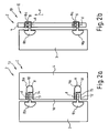
- FIGS. 2a and 2b is a simplified representation of a second partition 13 is shown.
- the second partition wall 13 is also designed as a shower partition wall 2 and comprises a wall element 3 and a door element 4, which are connected via hinge bands 8 and 9, wherein, in contrast to the in the FIGS. 1a and 1b shown first partition wall recesses 14 and 15 are not arranged on the wall element 3, but on a longitudinal edge 16 of the door element 4.
- the hinge bands 8 and 9 each comprise two wings 8a, 8b and 9a, 9b, which are rotatably connected to each other about a rotation axis d in the recess 14 and the recess 15.
- the hinge bands 8 and 9 are in turn designed as a so-called lifting-lowering joints 10. In one in the FIG.
- the recesses 14, 15 respectively below the hinge bands 8 and 9 free spaces 11 and 12, respectively.
- the door element 4 When opening the door element 4 from in the FIG. 2a shown lowered position I in one in the FIG. 2b shown raised position II, the door element 4 is lifted by the wings 8a and 9a in an arrow direction y in the direction of the axis of rotation d, thereby entering the free spaces 11 and 12, respectively.
- the free spaces 11, 12 are closed by in each case at least one sealing element, the display of sealing elements being omitted here for the sake of clarity.
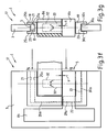
- FIG. 3a is a detailed view of a third partition wall 17 is shown, wherein the third partition 17 with respect to its basic structure with in the FIGS. 1a and 1b
- a wall element 3 has a recess 5, which is arranged on a longitudinal edge 7 of the wall element 3.
- the Indian FIG. 3a shown section of the partition 17 is part of a shower partition 2, which also otherwise comparable to that in the FIGS. 1a and 1b is shown, and in which a door element 4 is also fastened by means of two hinge bands on the wall element 3, wherein in the FIG. 3a only the upper hinge 8 is shown.
- the hinge 8 comprises a first wing 8 a, which is fixed to the door member 4, and a second wing 8 b, which is fixed to the wall element 3.
- the wings 8a and 8b of the hinge 8 are connected to each other in the recess 5 and have an axis of rotation d with each other, which runs parallel to the longitudinal edge 7 of the wall element 3.
- the hinge 8 is as a so-called lifting-lowering joint 10th executed.
- the third partition wall 17 comprises, in addition to the wall element 3, the door element 4 and the hinge 8, a first sealing element 18, a second sealing element 19 and a conventional door seal 20, which is fastened to the door element 4.
- In the FIG. 3a is the hinge I or the door element 4 in a lowered position I, in which the door element 4 is closed. In this lowered position I, the recess 5 is closed in the wall element 3 by the wings 8a and 8b and the two sealing elements 18 and 19 or sealed against spray water. With dashed lines edge edges 21, 22 and 23 are indicated, which limit the
- FIG. 3b are as individual parts of the FIG. 3a the wall element 3 with its recess 5, the first sealing element 18 and the second sealing element 19 shown.
- the recess 5 is bounded by the already mentioned marginal edges 21 to 23.
- the wall element 3 is preferably made of safety glass.
- the first sealing element 18 is formed by an L-shaped profile 24, which has two legs 25, 26.
- the two legs 25, 26 each have a U-shaped cross-section (see also FIG. 3g ). With dashed lines groove bottoms 25a and 25b indicated, which arise through this U-shaped cross-section.
- the first sealing element 18 forms a tab 27, which can be placed on the wall element 3 in the region of the cutout 5.
- the second sealing element 19 is likewise designed as an L-shaped profile 28, which has two legs 29 and 30.
- These two legs 29, 30 each have a U-shaped cross-section.
- the second sealing element 19 also forms a tab 31, which can be pushed onto the wall element 3 in the region of the recess 5. Pushing occurs in an arrow direction p, wherein after pushing the groove bottom 29a and the peripheral edge 22 and the groove bottom 30a and the peripheral edge 23 are opposite.
- FIG. 3c is as a further detail from the FIG. 3a the hinge 8 shown.
- Dashed lines show a sleeve 32 associated with the wing 8a and a sleeve 33 associated with the wing 8b which, when rotated about the axis of rotation d, raise in an arrowed direction y and then lower in an arrowed direction y 'of the wing 8a relative to the wing 8b effect.
- the sleeves 32, 33 extends in the direction of the axis of rotation d an unillustrated pin, which is connected to the wing 8b and on which the wing 8a in the direction of arrow y 'is attached.
- the hinge 8 shown in the 3d figure is again the hinge 8 shown. Unlike the Figure 3c show the 3d figure also the first sealing element 18, which is fastened with a fastening means 34 on the wing 8a of the hinge 8.
- the fastening means 34 allows a relative movement between the wing 8 a and the first sealing element 18, about the axis of rotation d.
- FIG. 3e the wall element 3 is shown with the already pushed second sealing element 19.
- FIG. 3e the hinge 8 with the mounted on the hinge 8 first sealing element 18, wherein the from 3d figure known fastener for clarity is not shown.
- the hinge 8 together with the first sealing element 18 forms an assembly which is intended to be inserted in an arrow direction x 'in the recess 5 of the wall element 3.
- FIG. 3f shows a view of the wall element 3, in which the FIG. 3e mentioned assembly already assembled is.
- the wing 8b is attached to the wall element 3, to maintain clarity, this attachment is not shown in the drawing.
- FIG. 3g is finally a cut through the representation of the FIG. 3f shown along the section line 3g-3g.
- the first sealing element 18 with its groove bottom 25a of the peripheral edge 21 of the recess 5 with a distance B is opposite and like webs 25b and 25c of the leg 25 of the first sealing member 18, the door element 3 engage around the side.
- the second sealing element 19 rests with its groove bottom 30a on the peripheral edge 23 of the recess 5 and laterally overlaps the door element 3 in the region of the peripheral edge 23 with webs 30b and 30c.
- the peripheral edge 22 of the recess 5 is surrounded by unspecified webs of the sealing elements 18 and 19 (see FIG. 3f ), wherein the sealing elements 18 and 19 lie with their groove bottoms 26a and 29a of the peripheral edge 22 of the recess opposite or abut against this.
- FIG. 3f show the FIG. 3h the partition 17 now in a raised position II of the wing 8a, in which the wing 8a together with the only in the FIG. 3a shown door element is pivoted by 90 ° about the axis of rotation d in the plane of the drawing.
- a distance between the wings 8a and 8b increases from a distance a in the lowered position I (see FIGS. 3f and 3g ) to a distance A in the raised position II (see FIGS. 3h and 3i ).
- the first sealing element 18 is displaced by the wing 8a of the hinge 8 in the direction of the arrow y and, with its groove bottom 25a, approaches the edge 21 of the recess 5 by a distance A-a.
- FIG. 3i is a side view on the appearance of the FIG. 3h shown from the direction of the arrow 3i.
- the first sealing element 18 is pulled by the wing 8a of the hinge 8 in an arrow y 'down, since it via the fastener 34 (see 3d figure ) is connected to this.
- the recess 5 is securely closed again in the lowered position I, since the first sealing element 18 is force-controlled via the wing 8.
- the second sealing element 19 is always in the same position in the positions I and II.
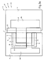
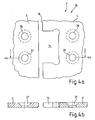
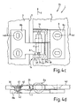
- FIGS. 4a to 4d show individual representations of a fourth partition wall 35, wherein the fourth partition 35 with respect to its basic structure with the in the FIGS. 2a and 2b shown second partition is comparable, since even with the partition wall 35, a door member 4 has a recess 14 which is arranged on a longitudinal edge 16 of the door member 4.
- the Indian FIG. 4a shown section of the partition 17 is part of a shower partition 2, which. also otherwise comparable to that in the FIGS. 2a and 2b shown second partition wall is formed and in which the door element 4 is also secured by means of two hinge straps on a wall element 3, wherein in the FIG. 3a only the wall element 3 and the door element 4 are shown.
- the wall element 3 and the door element 4 each have two conical bores 36 - 29 for attachment of the upper hinge band 8 (see Figure 4c ) on.
- FIG. 4b is a section through the depiction of FIG. 4a shown along the section line 4b-4b.
- the conical Holes 37 and 39 and the recess 14 can be seen.
- the wall element 3 and the door element 4 are formed of glass plates made of safety glass.
- FIG. 4d is a section through the depiction of Figure 4c shown along the section line 4d-4d. In this section is opposite to the Figure 4c In addition, a door seal 20 is shown, which is placed on the door element 3 and along a longitudinal edge 7 (see also Figure 4c ) of the door element 3 extends.
- the attachment of the hinge 8b in the conical bore 36 and in the other conical holes by means of a conical disc 40 with a threaded bore 41 and a countersunk screw 42. This results in an inner side 43 of the partition wall 35 a flush mounting of the hinge 8.
- first sealing element 18 is similar in terms of its shape to that in the FIGS. 3a to 3i executed shown first sealing element.
- the first sealing element 18 is connected by a fastening means 34 with the wing 8b of the hinge 8 rotatably about a rotational axis d of the hinge 8.
- closed position I of the partition wall 35 has a groove bottom 25a of the first sealing element 18 at a distance A to a peripheral edge 44 of the recess 14.
- a gap 45 which lies between the groove bottom 25a of the first sealing element 18 and the peripheral edge 44 of the recess 14 on the door element 4 is reduced. That is, the door member 4 pushes into the first stationary in the axial direction sealing element 19, wherein the first sealing member 19 rotates together with the door member 4 and the wing 8a of the hinge 8 about the axis of rotation 8.
- first sealing element form an elastically deformable seal, which can be stretched and squeezed.
Landscapes
- Health & Medical Sciences (AREA)
- Public Health (AREA)
- Epidemiology (AREA)
- General Health & Medical Sciences (AREA)
- Engineering & Computer Science (AREA)
- Mechanical Engineering (AREA)
- Hinges (AREA)
- Specific Sealing Or Ventilating Devices For Doors And Windows (AREA)
- Extensible Doors And Revolving Doors (AREA)
Applications Claiming Priority (1)
| Application Number | Priority Date | Filing Date | Title |
|---|---|---|---|
| DE200810012274 DE102008012274A1 (de) | 2008-03-03 | 2008-03-03 | Trennwand mit Gelenkband und Gelenkband für eine Trennwand |
Publications (3)
| Publication Number | Publication Date |
|---|---|
| EP2098148A2 true EP2098148A2 (fr) | 2009-09-09 |
| EP2098148A3 EP2098148A3 (fr) | 2011-04-27 |
| EP2098148B1 EP2098148B1 (fr) | 2018-09-26 |
Family
ID=40599972
Family Applications (1)
| Application Number | Title | Priority Date | Filing Date |
|---|---|---|---|
| EP09001734.4A Active EP2098148B1 (fr) | 2008-03-03 | 2009-02-07 | Paroi de séparation dotée d'une bande articulée |
Country Status (2)
| Country | Link |
|---|---|
| EP (1) | EP2098148B1 (fr) |
| DE (1) | DE102008012274A1 (fr) |
Cited By (2)
| Publication number | Priority date | Publication date | Assignee | Title |
|---|---|---|---|---|
| GB2563907A (en) * | 2017-06-29 | 2019-01-02 | Kohler Mira Ltd | Shower door hinge assembly |
| GB2581381A (en) * | 2019-02-15 | 2020-08-19 | Sum Chow Chi | Hinge for glass doors |
Families Citing this family (2)
| Publication number | Priority date | Publication date | Assignee | Title |
|---|---|---|---|---|
| DE202009013693U1 (de) | 2009-11-09 | 2010-01-07 | Munch, Paul-Jean | Rahmenlose Duschabtrennung |
| DE102019105018B4 (de) * | 2019-02-27 | 2020-09-24 | Joh. Sprinz Gmbh & Co. Kg | Scharnier mit elastischem Rückhalteelement |
Citations (1)
| Publication number | Priority date | Publication date | Assignee | Title |
|---|---|---|---|---|
| DE20304389U1 (de) | 2003-03-18 | 2003-06-05 | Altura Leiden Holding B.V., Vianen | Trennwand |
Family Cites Families (3)
| Publication number | Priority date | Publication date | Assignee | Title |
|---|---|---|---|---|
| DE202004000351U1 (de) * | 2004-01-13 | 2004-04-08 | Beck, Roland | Duschtürbeschlag mit Abdichtsystem |
| DE202006012415U1 (de) * | 2006-08-11 | 2006-11-23 | Schulte Duschkabinenbau Gmbh & Co. Kg | Scharnier und Duschabtrennung sowie Wandhalterung |
| DE202007001139U1 (de) * | 2007-01-19 | 2008-02-28 | Altura Leiden Holding B.V. | Trennwand, insbesondere Duschtrennwand |
-
2008
- 2008-03-03 DE DE200810012274 patent/DE102008012274A1/de not_active Withdrawn
-
2009
- 2009-02-07 EP EP09001734.4A patent/EP2098148B1/fr active Active
Patent Citations (1)
| Publication number | Priority date | Publication date | Assignee | Title |
|---|---|---|---|---|
| DE20304389U1 (de) | 2003-03-18 | 2003-06-05 | Altura Leiden Holding B.V., Vianen | Trennwand |
Cited By (5)
| Publication number | Priority date | Publication date | Assignee | Title |
|---|---|---|---|---|
| GB2563907A (en) * | 2017-06-29 | 2019-01-02 | Kohler Mira Ltd | Shower door hinge assembly |
| US11193316B2 (en) | 2017-06-29 | 2021-12-07 | Kohler Mira Limited | Shower door hinge assembly |
| GB2563907B (en) * | 2017-06-29 | 2022-06-08 | Kohler Mira Ltd | Shower door hinge assembly |
| GB2581381A (en) * | 2019-02-15 | 2020-08-19 | Sum Chow Chi | Hinge for glass doors |
| GB2581381B (en) * | 2019-02-15 | 2021-08-18 | Sum Chow Chi | Hinge |
Also Published As
| Publication number | Publication date |
|---|---|
| EP2098148A3 (fr) | 2011-04-27 |
| EP2098148B1 (fr) | 2018-09-26 |
| DE102008012274A1 (de) | 2009-09-10 |
Similar Documents
| Publication | Publication Date | Title |
|---|---|---|
| DE69225792T2 (de) | Mehrpunkt-türverriegelung mit nocken-ritzelementen | |
| AT502611B1 (de) | Scharnier | |
| EP2824270B1 (fr) | Élément de surface d'une verrière ignifuge, notamment porte en verre pour des applications anti-incendie pour éviter le passage du feu et de la fumée d'une pièce à une autre en cas d'incendie | |
| DE3010703A1 (de) | Tuerschliesseranordnung | |
| EP1707717A2 (fr) | Verrou rotatif à montage automatique | |
| EP2682545B1 (fr) | Dispositif de fermeture pour une porte coulissante ou une fenêtre coulissante, et porte coulissante ou fenêtre coulissante | |
| EP2098148B1 (fr) | Paroi de séparation dotée d'une bande articulée | |
| EP2245252B1 (fr) | Palier d'angle réglable pour vantail d'une fenêtre, d'une porte ou similaire | |
| CH665873A5 (de) | Scharnier zum beweglichen verbinden zweier teile, insbesondere fuer kuehlschraenke. | |
| DE102008004429A1 (de) | Endabdeckung für ein Gehäuse mit Stelleinrichtung und Vorrichtung zur Gehäuseanordnung an einem Flügel | |
| EP3425155B1 (fr) | Dispositif de protection anti-pince doigt pour une porte | |
| EP2142736B1 (fr) | Ferrure pour fenêtre, porte ou similaire | |
| EP3680443A1 (fr) | Portail à battant pivotant pourvu de système de protection contre le pincement | |
| EP2189091B1 (fr) | Séparation de douche | |
| EP2722472B1 (fr) | Ferrure pour battant et séparation de douche | |
| DE102008029320B3 (de) | Klemmbeschlag, Anschlagtür und Gargerät | |
| EP2374973B1 (fr) | Bande pour portes, fenêtres ou analogues | |
| EP1813754B1 (fr) | Ferme-porte | |
| EP3871575A1 (fr) | Charnière | |
| EP2175096B1 (fr) | Charnière d'un dispositif de fermeture, par exemple d'une fenêtre, d'une porte ou analogue, et dispositif de fermeture doté d'une telle charnière | |
| DE202004012023U1 (de) | Gelenkband für Glastüren | |
| DE202009001411U1 (de) | Vorrichtung zum Verschliessen eines Durchgangs | |
| EP1876319B1 (fr) | Coulisseau de guidage pour panneaux coulissants ou déplaçables selon un plan parallèle | |
| DE202007016708U1 (de) | Band für Türen, Fenster o.dgl. | |
| DE29808660U1 (de) | Tür- oder Fensterdrehband |
Legal Events
| Date | Code | Title | Description |
|---|---|---|---|
| PUAI | Public reference made under article 153(3) epc to a published international application that has entered the european phase |
Free format text: ORIGINAL CODE: 0009012 |
|
| AK | Designated contracting states |
Kind code of ref document: A2 Designated state(s): AT BE BG CH CY CZ DE DK EE ES FI FR GB GR HR HU IE IS IT LI LT LU LV MC MK MT NL NO PL PT RO SE SI SK TR |
|
| AX | Request for extension of the european patent |
Extension state: AL BA RS |
|
| RIC1 | Information provided on ipc code assigned before grant |
Ipc: E05D 7/00 20060101ALI20101124BHEP Ipc: A47K 3/36 20060101AFI20090619BHEP Ipc: E05F 1/04 20060101ALI20101124BHEP Ipc: E05D 5/02 20060101ALI20101124BHEP |
|
| PUAL | Search report despatched |
Free format text: ORIGINAL CODE: 0009013 |
|
| AK | Designated contracting states |
Kind code of ref document: A3 Designated state(s): AT BE BG CH CY CZ DE DK EE ES FI FR GB GR HR HU IE IS IT LI LT LU LV MC MK MT NL NO PL PT RO SE SI SK TR |
|
| AX | Request for extension of the european patent |
Extension state: AL BA RS |
|
| 17P | Request for examination filed |
Effective date: 20111027 |
|
| AKX | Designation fees paid |
Designated state(s): AT CH DE LI |
|
| GRAP | Despatch of communication of intention to grant a patent |
Free format text: ORIGINAL CODE: EPIDOSNIGR1 |
|
| STAA | Information on the status of an ep patent application or granted ep patent |
Free format text: STATUS: GRANT OF PATENT IS INTENDED |
|
| INTG | Intention to grant announced |
Effective date: 20180516 |
|
| GRAS | Grant fee paid |
Free format text: ORIGINAL CODE: EPIDOSNIGR3 |
|
| GRAA | (expected) grant |
Free format text: ORIGINAL CODE: 0009210 |
|
| STAA | Information on the status of an ep patent application or granted ep patent |
Free format text: STATUS: THE PATENT HAS BEEN GRANTED |
|
| AK | Designated contracting states |
Kind code of ref document: B1 Designated state(s): AT CH DE LI |
|
| REG | Reference to a national code |
Ref country code: CH Ref legal event code: EP |
|
| REG | Reference to a national code |
Ref country code: AT Ref legal event code: REF Ref document number: 1045023 Country of ref document: AT Kind code of ref document: T Effective date: 20181015 |
|
| REG | Reference to a national code |
Ref country code: DE Ref legal event code: R096 Ref document number: 502009015305 Country of ref document: DE |
|
| REG | Reference to a national code |
Ref country code: DE Ref legal event code: R097 Ref document number: 502009015305 Country of ref document: DE |
|
| PLBE | No opposition filed within time limit |
Free format text: ORIGINAL CODE: 0009261 |
|
| STAA | Information on the status of an ep patent application or granted ep patent |
Free format text: STATUS: NO OPPOSITION FILED WITHIN TIME LIMIT |
|
| 26N | No opposition filed |
Effective date: 20190627 |
|
| REG | Reference to a national code |
Ref country code: CH Ref legal event code: PL |
|
| PG25 | Lapsed in a contracting state [announced via postgrant information from national office to epo] |
Ref country code: CH Free format text: LAPSE BECAUSE OF NON-PAYMENT OF DUE FEES Effective date: 20190228 Ref country code: LI Free format text: LAPSE BECAUSE OF NON-PAYMENT OF DUE FEES Effective date: 20190228 |
|
| REG | Reference to a national code |
Ref country code: AT Ref legal event code: MM01 Ref document number: 1045023 Country of ref document: AT Kind code of ref document: T Effective date: 20190207 |
|
| PG25 | Lapsed in a contracting state [announced via postgrant information from national office to epo] |
Ref country code: AT Free format text: LAPSE BECAUSE OF NON-PAYMENT OF DUE FEES Effective date: 20190207 |
|
| REG | Reference to a national code |
Ref country code: DE Ref legal event code: R082 Ref document number: 502009015305 Country of ref document: DE Representative=s name: RAVENSPAT PATENTANWAELTE PARTNERSCHAFT MBB, DE |
|
| PGFP | Annual fee paid to national office [announced via postgrant information from national office to epo] |
Ref country code: DE Payment date: 20260217 Year of fee payment: 18 |