EP2189091B1 - Séparation de douche - Google Patents
Séparation de douche Download PDFInfo
- Publication number
- EP2189091B1 EP2189091B1 EP10001694A EP10001694A EP2189091B1 EP 2189091 B1 EP2189091 B1 EP 2189091B1 EP 10001694 A EP10001694 A EP 10001694A EP 10001694 A EP10001694 A EP 10001694A EP 2189091 B1 EP2189091 B1 EP 2189091B1
- Authority
- EP
- European Patent Office
- Prior art keywords
- hinge
- door
- longitudinal edge
- bearing body
- shower partition
- Prior art date
- Legal status (The legal status is an assumption and is not a legal conclusion. Google has not performed a legal analysis and makes no representation as to the accuracy of the status listed.)
- Revoked
Links
Images


Classifications
-
- E—FIXED CONSTRUCTIONS
- E05—LOCKS; KEYS; WINDOW OR DOOR FITTINGS; SAFES
- E05D—HINGES OR SUSPENSION DEVICES FOR DOORS, WINDOWS OR WINGS
- E05D11/00—Additional features or accessories of hinges
-
- A—HUMAN NECESSITIES
- A47—FURNITURE; DOMESTIC ARTICLES OR APPLIANCES; COFFEE MILLS; SPICE MILLS; SUCTION CLEANERS IN GENERAL
- A47K—SANITARY EQUIPMENT; ACCESSORIES THEREFOR, e.g. TOILET ACCESSORIES
- A47K3/00—Baths; Showers; Appurtenances therefor
- A47K3/28—Showers or bathing douches
- A47K3/30—Screens or collapsible cabinets for showers or baths
- A47K3/36—Articulated screens
-
- E—FIXED CONSTRUCTIONS
- E05—LOCKS; KEYS; WINDOW OR DOOR FITTINGS; SAFES
- E05D—HINGES OR SUSPENSION DEVICES FOR DOORS, WINDOWS OR WINGS
- E05D11/00—Additional features or accessories of hinges
- E05D11/10—Devices for preventing movement between relatively-movable hinge parts
- E05D11/1028—Devices for preventing movement between relatively-movable hinge parts for maintaining the hinge in two or more positions, e.g. intermediate or fully open
- E05D11/105—Devices for preventing movement between relatively-movable hinge parts for maintaining the hinge in two or more positions, e.g. intermediate or fully open the maintaining means acting perpendicularly to the pivot axis
-
- E—FIXED CONSTRUCTIONS
- E05—LOCKS; KEYS; WINDOW OR DOOR FITTINGS; SAFES
- E05D—HINGES OR SUSPENSION DEVICES FOR DOORS, WINDOWS OR WINGS
- E05D5/00—Construction of single parts, e.g. the parts for attachment
- E05D5/02—Parts for attachment, e.g. flaps
- E05D5/0246—Parts for attachment, e.g. flaps for attachment to glass panels
-
- E—FIXED CONSTRUCTIONS
- E05—LOCKS; KEYS; WINDOW OR DOOR FITTINGS; SAFES
- E05D—HINGES OR SUSPENSION DEVICES FOR DOORS, WINDOWS OR WINGS
- E05D3/00—Hinges with pins
- E05D3/02—Hinges with pins with one pin
- E05D2003/025—Hinges with pins with one pin having three knuckles
- E05D2003/027—Hinges with pins with one pin having three knuckles the end knuckles being mutually connected
-
- E—FIXED CONSTRUCTIONS
- E05—LOCKS; KEYS; WINDOW OR DOOR FITTINGS; SAFES
- E05D—HINGES OR SUSPENSION DEVICES FOR DOORS, WINDOWS OR WINGS
- E05D5/00—Construction of single parts, e.g. the parts for attachment
- E05D5/02—Parts for attachment, e.g. flaps
- E05D5/0246—Parts for attachment, e.g. flaps for attachment to glass panels
- E05D2005/0261—Parts for attachment, e.g. flaps for attachment to glass panels connecting two or more glass panels
- E05D2005/0269—Parts for attachment, e.g. flaps for attachment to glass panels connecting two or more glass panels the panels being coplanar
-
- E—FIXED CONSTRUCTIONS
- E05—LOCKS; KEYS; WINDOW OR DOOR FITTINGS; SAFES
- E05Y—INDEXING SCHEME ASSOCIATED WITH SUBCLASSES E05D AND E05F, RELATING TO CONSTRUCTION ELEMENTS, ELECTRIC CONTROL, POWER SUPPLY, POWER SIGNAL OR TRANSMISSION, USER INTERFACES, MOUNTING OR COUPLING, DETAILS, ACCESSORIES, AUXILIARY OPERATIONS NOT OTHERWISE PROVIDED FOR, APPLICATION THEREOF
- E05Y2800/00—Details, accessories and auxiliary operations not otherwise provided for
- E05Y2800/10—Additional functions
- E05Y2800/12—Sealing
-
- E—FIXED CONSTRUCTIONS
- E05—LOCKS; KEYS; WINDOW OR DOOR FITTINGS; SAFES
- E05Y—INDEXING SCHEME ASSOCIATED WITH SUBCLASSES E05D AND E05F, RELATING TO CONSTRUCTION ELEMENTS, ELECTRIC CONTROL, POWER SUPPLY, POWER SIGNAL OR TRANSMISSION, USER INTERFACES, MOUNTING OR COUPLING, DETAILS, ACCESSORIES, AUXILIARY OPERATIONS NOT OTHERWISE PROVIDED FOR, APPLICATION THEREOF
- E05Y2800/00—Details, accessories and auxiliary operations not otherwise provided for
- E05Y2800/15—Applicability
- E05Y2800/16—Applicable on combinations of fixed and movable wings
- E05Y2800/162—Applicable on combinations of fixed and movable wings the wings being coplanar when the movable wing is in the closed position
-
- E—FIXED CONSTRUCTIONS
- E05—LOCKS; KEYS; WINDOW OR DOOR FITTINGS; SAFES
- E05Y—INDEXING SCHEME ASSOCIATED WITH SUBCLASSES E05D AND E05F, RELATING TO CONSTRUCTION ELEMENTS, ELECTRIC CONTROL, POWER SUPPLY, POWER SIGNAL OR TRANSMISSION, USER INTERFACES, MOUNTING OR COUPLING, DETAILS, ACCESSORIES, AUXILIARY OPERATIONS NOT OTHERWISE PROVIDED FOR, APPLICATION THEREOF
- E05Y2800/00—Details, accessories and auxiliary operations not otherwise provided for
- E05Y2800/26—Form or shape
- E05Y2800/292—Form or shape having apertures
-
- E—FIXED CONSTRUCTIONS
- E05—LOCKS; KEYS; WINDOW OR DOOR FITTINGS; SAFES
- E05Y—INDEXING SCHEME ASSOCIATED WITH SUBCLASSES E05D AND E05F, RELATING TO CONSTRUCTION ELEMENTS, ELECTRIC CONTROL, POWER SUPPLY, POWER SIGNAL OR TRANSMISSION, USER INTERFACES, MOUNTING OR COUPLING, DETAILS, ACCESSORIES, AUXILIARY OPERATIONS NOT OTHERWISE PROVIDED FOR, APPLICATION THEREOF
- E05Y2900/00—Application of doors, windows, wings or fittings thereof
- E05Y2900/10—Application of doors, windows, wings or fittings thereof for buildings or parts thereof
- E05Y2900/114—Application of doors, windows, wings or fittings thereof for buildings or parts thereof for showers
Definitions
- the invention relates to a shower enclosure according to the features specified in the preamble of claim 1.
- Such a shower enclosure is from the DE 296 04 702 U1 known, the door element is pivotally mounted with respect to a further element by means of at least one hinge.
- the hinge comprises two hinge parts coupled by means of a hinge pin, which are connected to the door element or the further element, wherein these each have mutually associated vertical longitudinal edges.
- One of the said hinge parts at least partially engages in a recess of the door element or of the further element.
- the hinge pin provided for coupling the hinge parts is arranged in the region of said vertical longitudinal edges.
- a shower enclosure known which includes a pivotable about a substantially vertical axis of rotation door element.
- the axis of rotation is predetermined by means of at least one hinge, wherein regularly spaced two such hinges in the vertical direction, expediently provided in the region of the upper and at the lower end of the door element.
- Said door element is articulated by means of the hinges to a fixed wall element or to another likewise pivotally mounted door element, wherein for sealing in the closed position of the door element with respect to the further element in the region of the mutually facing vertical longitudinal edges thereof may be arranged a sealing element.
- the door element can be opened from the closed position, in which it is in particular in a plane substantially parallel to the plane of the further element, only in one direction in the order of 90 degrees.
- the hinges contain on the one hand a bearing block and on the other hand a hinge pin, which defines the mentioned axis of rotation.
- the size of the torque for opening and / or closing the door element can vary within a wide range, due to changing environmental conditions, in particular the humidity, and the ingress of spray, if necessary in conjunction with soap, calcium deposits, penetrating dirt particles or the like.
- said torque may vary over the useful life of many years of such a shower enclosure.
- a low torque and thus too easy current pivoting of the door element is just as undesirable in terms of a possible impact with another component or the user as to be performed with too much effort pivoting of the door element, especially since there is a risk of injury to the user can.
- a hinge for two plate-shaped elements which contains a return means by an elastic ring.
- the one element contains a recess open to the vertical longitudinal edge, in which part of the first hinge part and the hinge pin and further the elastic ring are arranged. In this recess also engages connected to the other hinge part bearing block or bearing body, in which the hinge pin is also inserted.
- the bearing block is integrally formed by means of a connecting member with the other hinge part, wherein in the closed position of the two elements between the mutually facing vertical longitudinal edges, a small gap is present.
- the connecting component and the said bearing block are arranged substantially in the center plane of the further element.
- the outer surface of the bearing block is formed as a prismatic cam and is applied to the elastic ring of the associated hinge part of the first element such that defined angular positions between the two elements can be predetermined. Due to the mentioned gap between the longitudinal edges of the two elements in the closed position, the use in shower enclosures is not readily possible.
- a hinged door for a shower partition with hinges which on the one hand have a wall-side band connected to an anchoring profile and on the other hand a door-side band connected to the hinged door or the door element.
- the wall-side band part has two halves, which in the closed position penetrate the gap between the anchoring profile and the door element or protrude into the gap mentioned.
- the door-side hinge or hinge part projects into the gap in the closed position. The seal is arranged outside the gap and the wall-side band parts penetrate or engage in the gap.
- the invention has the object, the shower enclosure of the type mentioned with little design effort to the effect that the door element can be pivoted in a simple and defined manner both when opening and closing, in the closed position a functionally reliable seal, especially in Range of the hinge, to be guaranteed.
- the shower enclosure and in particular their hinge should have a low volume and allow easy handling.
- the hinge should be able to be produced with low production costs and require little installation effort for producing the connection of the pivotable door element or door leaf with the other element, be it a further door element or a fixed wall element or the like.
- the proposed shower enclosure is characterized by a simple and functional design and also ensures in the area of the hinge or hinges due to the continuous sealing element in the closed position of the door element a secure seal against the escape of spray out of the shower room to the outside.
- a sufficiently large clearance for the sealing element is provided, which is arranged on one longitudinal edge and at least in the closed position on the opposite other longitudinal edge and in the region of the hinge to a sealing surface, in particular one Body and / or the bearing body, sealingly applied.
- the sealing element extends continuously, preferably at least approximately, over the entire vertical height of the longitudinal edges and is in particular integrally formed, wherein in the region of the hinge or hinges in cooperation with the existing there sealing surface of a recess of the door element odes of the further element associated body for shower enclosures important sealing is realized with little effort.
- the sealing surface of the body, in particular of the bearing body is aligned at least approximately with that vertical longitudinal edge on which the sealing element rests.
- the one or more hinges of the proposed shower enclosure are designed as pendulum hinges, which allow opening of the door element in both directions, expedient over at least approximately at least 90 degrees from the closed position.
- the hinge pin and the first hinge part are preferably arranged in the region of a recess, in particular the plate made of glass of the door element or the further element, wherein the axis of rotation is at least approximately in the plane passing through said plate vertical plane, so that as a result a compact Construction as well as a shapely design is guaranteed.
- the door element can be pivoted from the closed position to the shower interior via the shower or bathtub or into the exterior space, in each case over a pivoting range of preferably at least 90 degrees.
- the continuous sealing element provided, which ensures a functionally reliable seal in the region of the hinge or on the there provided sealing surface of said body, in particular the bearing body.
- the recess is preferably designed to be open to the vertical longitudinal edge, whereby the opening of the recess present in the region of the longitudinal edge is closed off by means of the body whose outer surface forms said sealing surface.
- the recess may be closed towards the longitudinal edge and designed as a bore spaced from the longitudinal edge for receiving the bearing body and the hinge pin.
- the continuous sealing element is located in the hinge region on the local part of the vertical longitudinal edge.
- Fig. 1 shows a detail of a partial view of the shower enclosure in the region of a hinge 2, by means of which a door element 4 with respect to a further element 6 is pivotally mounted about a substantially vertical axis of rotation 8.
- the hinge 2 is located at a predetermined distance below the upper edge 10 of the door element 4 and the upper edge 12 of the further element 6.
- the further element 6 may be formed as a fixed wall element as well as a second door element, which by means of another left edge according to drawing of the element 6 is arranged.
- a second matching formed hinge is arranged, which also defines the axis of rotation 8.
- a sealing element 18 is provided, by means of which the free space between said longitudinal edges is sealed.
- the sealing element 18 is advantageously arranged on the vertical longitudinal edge 16 of the element 6 and secured in a suitable manner. It is of particular importance that the sealing element 18 also extends continuously over the region of the hinge 2 shown here, as well as over the region of the mentioned further lower hinge, so that a functionally reliable seal is also ensured in the area of the hinge (s).
- the sealing element 18 is sealingly on the vertical longitudinal edge 14 as sealingly as on a provided in a vertical extension of the same sealing surface 19 of a body and / or a hinge part, as will be explained below.
- the hinge 2 includes a first hinge part 20, which is connected to the first door member 4 and has a hinge pin, and a further hinge part 22, which has a bearing body 24 for said hinge pin.
- the bearing body 24 forms said body with the sealing surface 19.
- the two hinge parts 20 and 22 are fixedly connected to the door element 4 and the other element 6, which will be discussed below.
- the hinge 2 can be arranged about a vertical axis by 180 ° such that the hinge part 20 the further element 6 and the further hinge part 22 is associated with the door element 4, wherein the axis of rotation 8 is located in the region of the further element 6 and the sealing element 18 is arranged and fixed to the vertical longitudinal edge 14 of the door element 4 and thus sealingly abuts against the vertical longitudinal edge 16 of the further element 6.
- Fig. 2 shows a top view of the shower enclosure in the region of the hinge 2.
- the door element 4 is suitably formed as a plate, in particular of silicate glass, and correspondingly also the further element 6.
- a frame surrounding the plate is not present, and it lies thus a so-called frameless shower enclosure.
- a free space 25 is present in the closed position of the door element 4, in which the sealing element 18 is arranged.
- the sealing element contains the further element 6 on the longitudinal edge 16 U-shaped cross-leg, wherein preferably via a clamping connection and / or with adhesives secure attachment to or in the region of the longitudinal edge 16 is present.
- the elastic sealing element 18 is located on the opposite vertical longitudinal edge 14 and the hand of Fig.
- the longitudinal edges 14 and 16 are in the closed position with the distance 23 opposite each other.
- the door element 4 from the illustrated closed position in two directions, namely inwardly over the shower interior and outwardly into the outer space out, in each case at predetermined angles, preferably in the order of 90 ° , so that the entire rotation angle range is at least approximately 180 °.
- the predefined with the pendulum hinge 2 vertical axis of rotation 8 preferably extends approximately in the vertical center plane of the door member 4.
- the continuous sealing element 18 is arranged, which with the further element 6 is connected.
- the sealing element 18 includes an on the vertical longitudinal edge of the door member 4 and said sealing surface 19 of the body 24, in particular of the bearing body, sealingly fitting sealing surface 28th
- the two hinge parts 20 and 22 are opposite on the other side of the door element 4 and the other element 6 covers 30 and 32 indicated.
- dashed lines 34 in particular screw connections of the first hinge part 20 with the one cover 30 and between the other hinge part 22 and the cover 32 are indicated, wherein the door member 4 and the further element 6 associated holes for the corresponding fasteners or screws included.
- the connection of said hinge parts 20, 22 and / or the covers 30, 32 may be made with the door member 4 and the further element 6 by adhesive.
- Fig. 3 shows a section through the hinge in a horizontal sectional plane, on the one hand, the already mentioned hinge pin 35 of the first hinge part 20 and on the other hand, the bearing body 24 of the further hinge part 22 are clearly visible.
- the bearing body 24 includes with respect to the vertical longitudinal edge 16 and spaced therefrom, the said sealing surface 19, on which the arranged in the free space 25 and attached to the vertical longitudinal edge 16 of the further element 6 sealing element 18 sealingly.
- the bearing body 24 is connected by means of a connecting arm 37 with the plate-shaped part 39 of the further hinge part 22.
- the connecting arm 37 is arranged in extension of the plate-shaped part 39, which is arranged on the outer side of the further element 6, and thus bridges the free space 25.
- the connecting arm 37 of the further hinge part 22 is arranged laterally of the free space 25, which is open in an advantageous manner to the other side of the further element 6.
- the further hinge part 22 projects beyond the vertical longitudinal edge 16 of the further element 6 with the connecting arm 37, to which the bearing body 24 thus has a predetermined distance.
- the sealing surface 19 is at least approximately aligned with the vertical longitudinal edge of the door member 4, not shown here, and consequently the distance between the sealing surface 19 and the longitudinal edge 16 at least approximately the same size as the above-explained distance between the vertical longitudinal edge of the door member 4 and the vertical longitudinal edge 16 of the further element. 6
- the bearing body 24 contains inside a cavity 38, in which the hinge pin 35 protrudes.
- two leaf springs 40, 41 are further arranged, which bear against the outer surface of the hinge pin 35 under predetermined and / or at least approximately radial bias.
- a single such leaf spring is sufficient in principle, but in a preferred manner, the two leaf springs 40, 41 are provided, between which the hinge pin 35 is located.
- the bearing body 24 to the cavity 38 open recesses 42.
- the leaf springs 40, 41 is defined in a defined manner a friction with respect to the hinge pin 35, so that as far as possible from external influences independent torque for pivoting the door member 4 is present.
- the outer surface of the hinge pin 35 is preferably provided with two diametrically arranged flats 43 or flattened in the contact region of the leaf springs 40, 41, so that a defined closing position for the door element 4 is predetermined.
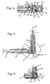
- Fig. 4 shows a top view of the shower enclosure similar Fig. 2 However, wherein the door member 4 is pivoted with respect to the further element 6 by an angle of 90 °.
- the passage from an outside space into a shower interior or vice versa is given freely, while in the closed position of the door element 4 according to FIG Fig. 1 to 3 the passage is shut off.
- the sealing element 18 is no longer sealingly against the vertical longitudinal edge 14 of the door leaf 4, but on the free surface of the cover 30, where appropriate to the free surface of the door member 4, a gap may be present.
- FIG. 5 represented detail V according to Fig. 4 shows a section through the hinge in a horizontal sectional plane accordingly Fig. 3 , but with the door element 4 is pivoted with respect to the further element 6 by 90 °.
- the sealing element 18 abuts unchanged on the sealing surface 19 of the bearing body 24.
- the bearing body 24 has a coaxial to the rotation axis 8 outer surface 44, and corresponding thereto, a part of the first hinge part 20 has a partially hollow cylindrical inner surface 45.
- the said surfaces 44, 45 are in particular with little play or against each other, so that a secure guidance of the door element 4 is ensured when pivoting about the axis of rotation 8.
- the hinge pin 35 has additional lateral flats 46 for the spring elements or leaf springs in such a way that a closer locking of the door element is ensured even in the open position.
- the hinge pin 35 thus has two further, diametrically arranged flats 46, which with respect to the axis of rotation 8 to the on hand of Fig. 3 explained flats 43 are arranged offset by 90 °.
- the hinge pin 35 in the region of the leaf springs four each offset by 90 ° to each other lying flats 43, 46 and thus a rectangular and preferably square cross section.
- Fig. 6 shows a section along section line A according to Fig. 4 In the vertical center plane of the door element 4.
- the bearing body 24 engages partially in the recess 48 and also a hinge body 50 of the first hinge part.
- the hinge body 50 is preferably formed integrally with the first hinge part, but it may alternatively, in particular via a screw connection, be connected to the first hinge part and the associated cover.
- the hinge pin 35 penetrates the bearing body 24 and protrudes with its cylindrical ends 52, 53 into corresponding recesses of the hinge body 50.
- the bearing body 24 engages in a free space between an upper and a lower leg 54, 55 of the hinge body 50, wherein between said Legs 54, 55 and the engaging part of the bearing body 24 is a disk-shaped element 56, 57 is arranged.
- the disc-shaped elements 56, 57 are part of a body arranged in the hinge body 50, which preferably consists of a material with good sliding properties, in particular PTFE.
- a defined friction is predetermined by means of the leaf springs 40, 41 resting under pretension on the outer surface of the hinge pin 35.
- one of the holes 60 already mentioned can be seen in the door element 4, through which a connection or fastening element 62 of the first hinge part engages with the door element 4 or the cover element mentioned. Since the bore 60 has a larger inner diameter by a predetermined amount than the outer diameter of the connecting element 62, a corresponding alignment of the first hinge part with respect to the door element 4 can be made in a preferred manner.
- the pivotable door member 4 includes the recess 48 for receiving the hinge pin 35 and the hinge body 50, wherein the bearing body 24 of the further hinge part 22 is fixedly connected to the further element 6.
- the further element 6 may include the recess and the bearing body 24 may be connected by analogy with the door element by means of the further hinge part.
- the above explanations apply analogously.
Landscapes
- Engineering & Computer Science (AREA)
- Mechanical Engineering (AREA)
- Health & Medical Sciences (AREA)
- Public Health (AREA)
- Epidemiology (AREA)
- General Health & Medical Sciences (AREA)
- Hinges (AREA)
- Specific Sealing Or Ventilating Devices For Doors And Windows (AREA)
- Extensible Doors And Revolving Doors (AREA)
Claims (9)
- Séparation de douche comprenant un élément formant porte (4), logé en étant pivotant autour d'un axe de rotation (8) par rapport à un autre élément (6) au moyen d'au moins une charnière (2) d'une position de fermeture dans une position ouverte et inversement, la charnière (22) comprenant une première pièce de charnière (20) avec un boulon de charnière (35) et une autre pièce de charnière (22) avec un corps de logement (24) pour le boulon de charnière (35), l'élément formant porte (4) et l'autre élément (6) comportant par ailleurs chacun des arêtes longitudinales (14, 16) verticales respectivement associées et le corps de logement (24) s'engageant au moins en partie dans un évidement (48) de l'élément formant porte (4) ou de l'autre élément (6),
caractérisée en ce que dans la position de fermeture, un espace libre (25) est présent entre les arêtes longitudinales (14, 16) qui se font face, en ce que latéralement, à côté de l'espace libre (25) et chevauchant ce dernier, l'autre pièce de charnière (22) comporte un bras de liaison (37) pour le corps de logement (24) et en ce que dans l'espace libre (25), sur l'arête longitudinale verticale (16, 14) de l'autre élément (6) ou de l'élément formant porte (4) est disposé un élément d'étanchéité (18), qui est conçu en version traversante par-dessus la zone de la charnière (2) et dans la position de fermeture s'applique en formant étanchéité sur l'arête longitudinale (14, 16) de l'élément formant porte (4) ou de l'autre élément (6) ou encore sur une surface d'étanchéité (19) d'un corps (24) associé à l'évidement (48), tout comme sur l'arête longitudinale (14, 16) s'y raccordant vers le haut et vers le bas de l'élément formant porte (4) ou de l'autre élément (6). - Séparation de douche selon la revendication 1, caractérisée en ce que le bras de liaison (37) est conçu en tant que prolongement d'une pièce (38), de préférence en forme de plaque de l'autre élément de charnière (22), la pièce en forme de plaque (38) étant disposée sur la surface latérale de l'autre élément (6) et/ou en ce que le corps de logement (24) et le bras de liaison (37) ainsi que la pièce (38) citée de l'autre pièce de charnière (22) sont conçus en monobloc.
- Séparation de douche selon la revendication 1 ou 2, caractérisé en ce que le corps (24) est disposé dans la région de l'ouverture de l'évidement (48) ouvert sur l'arête longitudinale verticale (14) et/ou en ce que le corps (24) est le corps de logement et/ou en ce que la surface d'étanchéité (19) du corps (24) est disposée au moins approximativement dans le même plan vertical que l'arête longitudinale verticale (14) de l'élément formant porte (4).
- Séparation de douche selon l'une quelconque des revendications 1 à 3, caractérisée en ce que dans l'évidement (48) est disposé un corps de charnière (50) dans lequel le boulon de charnière (35), notamment ses extrémités cylindriques (52, 53) sont logés.
- Séparation de douche selon l'une quelconque des revendications 1 à 4, caractérisée en ce que le corps de logement (24) comporte une cavité (38) dans laquelle le boulon de charnière (35) s'engage au moins en partie.
- Séparation de douche selon l'une quelconque des revendications 1 à 5, caractérisé en ce que l'élément d'étanchéité (18) s'étend en continuité sensiblement sur toute la hauteur verticale de l'élément formant porte (4) et/ou de l'autre élément (6) et est conçu en version traversante dans la région de la charnière (2), l'élément d'étanchéité (18) étant fixé sur l'une des arêtes longitudinales verticales (16) et dans la position de fermeture, s'appliquant de façon étanche sur l'autre arête longitudinale (14).
- Séparation de douche selon l'une quelconque des revendications 4 à 6, caractérisé en ce que le corps de logement (24) est disposé entre deux branches (54, 55) disposées avec un écart axial du corps de charnière (50).
- Séparation de douche selon l'une quelconque des revendications 4 à 7, caractérisée en ce qu'en direction axiale entre le corps de logement (24) et les branches (54, 55) citées est disposé un élément en forme de disque (56, 57), qui fait preuve notamment d'un faible coefficient de frottement, et/ou en ce que l'élément en forme de disque (56, 57) est une partie intégrante d'un corps (58) constitué notamment en matière plastique.
- Séparation de douche selon l'une quelconque des revendications 1 à 8, caractérisée en ce que le corps de logement (24) présente une surface extérieure (44) sensiblement coaxiale à l'axe de rotation (8) et/ou cylindrique et en ce que la première pièce de charnière (20) comprend une surface intérieure (45) correspondante, en partie cylindrique, un jeu prédéfini étant de préférence prévu par rapport à la surface extérieure (44) citée.
Applications Claiming Priority (2)
| Application Number | Priority Date | Filing Date | Title |
|---|---|---|---|
| DE20201086U DE20201086U1 (de) | 2002-01-24 | 2002-01-24 | Duschabtrennung |
| EP03001496A EP1331335B1 (fr) | 2002-01-24 | 2003-01-23 | Séparation de douche |
Related Parent Applications (2)
| Application Number | Title | Priority Date | Filing Date |
|---|---|---|---|
| EP03001496.3 Division | 2003-01-23 | ||
| EP03001496A Division EP1331335B1 (fr) | 2002-01-24 | 2003-01-23 | Séparation de douche |
Publications (2)
| Publication Number | Publication Date |
|---|---|
| EP2189091A1 EP2189091A1 (fr) | 2010-05-26 |
| EP2189091B1 true EP2189091B1 (fr) | 2012-08-22 |
Family
ID=7966951
Family Applications (2)
| Application Number | Title | Priority Date | Filing Date |
|---|---|---|---|
| EP10001694A Revoked EP2189091B1 (fr) | 2002-01-24 | 2003-01-23 | Séparation de douche |
| EP03001496A Expired - Lifetime EP1331335B1 (fr) | 2002-01-24 | 2003-01-23 | Séparation de douche |
Family Applications After (1)
| Application Number | Title | Priority Date | Filing Date |
|---|---|---|---|
| EP03001496A Expired - Lifetime EP1331335B1 (fr) | 2002-01-24 | 2003-01-23 | Séparation de douche |
Country Status (3)
| Country | Link |
|---|---|
| EP (2) | EP2189091B1 (fr) |
| DE (1) | DE20201086U1 (fr) |
| ES (1) | ES2390563T3 (fr) |
Families Citing this family (6)
| Publication number | Priority date | Publication date | Assignee | Title |
|---|---|---|---|---|
| DE20304389U1 (de) * | 2003-03-18 | 2003-06-05 | Altura Leiden Holding B.V., Vianen | Trennwand |
| TWI359227B (en) | 2009-02-17 | 2012-03-01 | Combao Internat Co Ltd | Hinge device of glass door |
| TWI350336B (en) * | 2009-02-17 | 2011-10-11 | Combao Internat Co Ltd | Hinge device of glass door |
| DE202009002985U1 (de) * | 2009-03-05 | 2010-04-29 | Altura Leiden Holding B.V. | Scharniersystem für Trennwände |
| EP2492424B1 (fr) | 2011-02-23 | 2016-05-25 | Altura Leiden Holding B.V. | Dispositif de raccordement d'un mur de séparation, notamment paroi de séparation de douche |
| GB2563907B (en) * | 2017-06-29 | 2022-06-08 | Kohler Mira Ltd | Shower door hinge assembly |
Family Cites Families (10)
| Publication number | Priority date | Publication date | Assignee | Title |
|---|---|---|---|---|
| DE14076C (de) | J. BERNOULLI & CO. in Basel | Mechanische Beschläge für Thüren, Läden und Fenster | ||
| DE3335575C2 (de) | 1983-09-30 | 1987-05-07 | Hermann Hans 8750 Aschaffenburg Urlberger | Vorrichtung zum Arretieren eines gegenüber einer Welle drehbaren Teils |
| DE8616362U1 (de) | 1986-06-19 | 1987-10-22 | Hüppe GmbH, 2900 Oldenburg | Duschabtrennung für Bade- oder Duschwannen |
| DE3901395A1 (de) | 1989-01-19 | 1990-08-02 | Munch Paul Jean | Schwenktuere fuer duschtrennwand |
| DE4215526C2 (de) | 1991-05-13 | 1996-08-14 | Manuela Huber | Horizontal zweigeteilte Dusche mit Abtrennelement(en) und 360 GRD-Schwenkbereich insbesondere für pflegebedürftige Personen |
| EP0797718B1 (fr) | 1995-10-17 | 2000-04-05 | E.P.I., Européenne de Participations Industrielle, Société Anonyme | Arret de porte provisoire pour charniere d'une porte de vehicule automobile et dispositif de fixation d'un tel arret de porte provisoire |
| DE29604702U1 (de) | 1996-03-14 | 1996-05-15 | Dudek, Günter, Dipl.-Ing., 26215 Wiefelstede | Scharnier für Duschabtrennungsglastüren |
| FR2748515B1 (fr) | 1996-05-09 | 1999-08-20 | Adler Sa | Charniere a systeme de rappel par anneau elastique |
| DE29700447U1 (de) | 1997-01-13 | 1997-02-27 | Altura Leiden Holding B.V., Vianen | Duschabtrennung |
| DE29910496U1 (de) | 1999-06-16 | 1999-08-12 | Altura Leiden Holding B.V., Vianen | Duschtrennwand |
-
2002
- 2002-01-24 DE DE20201086U patent/DE20201086U1/de not_active Expired - Lifetime
-
2003
- 2003-01-23 ES ES10001694T patent/ES2390563T3/es not_active Expired - Lifetime
- 2003-01-23 EP EP10001694A patent/EP2189091B1/fr not_active Revoked
- 2003-01-23 EP EP03001496A patent/EP1331335B1/fr not_active Expired - Lifetime
Also Published As
| Publication number | Publication date |
|---|---|
| EP1331335A3 (fr) | 2009-09-02 |
| EP1331335A2 (fr) | 2003-07-30 |
| EP2189091A1 (fr) | 2010-05-26 |
| ES2390563T3 (es) | 2012-11-14 |
| DE20201086U1 (de) | 2002-04-25 |
| EP1331335B1 (fr) | 2012-12-19 |
Similar Documents
| Publication | Publication Date | Title |
|---|---|---|
| WO2005088052A1 (fr) | Dispositif amortisseur pour des charnieres de meubles | |
| DE3515907A1 (de) | Scharnier, insbesondere moebelscharnier | |
| DE10034071B4 (de) | Einrichtung zum Verschließen einer Öffnung | |
| EP1946686B1 (fr) | Cloison de séparation, en particulier cloison de douche | |
| EP2189091B1 (fr) | Séparation de douche | |
| EP1460220A2 (fr) | Cloison | |
| EP2233670A2 (fr) | Charnière et séparation de douche | |
| DE3104973A1 (de) | "aufschraubband, insbesondere fuer schwere fenster- oder tuerfluegel mit kunststoffprofilen" | |
| EP3695080B1 (fr) | Ferrure rotative destinée à être agencée de manière dissimulée sur des fenêtres ou des portes | |
| DE102020207128B3 (de) | Scharnier mit integrierter Anschlagdämpfung | |
| EP2098148B1 (fr) | Paroi de séparation dotée d'une bande articulée | |
| DE29609039U1 (de) | Schnappriegelvorrichtung für Flügel von Fenstern, Türen o.dgl. | |
| DE19944549B4 (de) | Verschwindscharnier | |
| EP1127527A2 (fr) | Ferrure pour écran de douche avec joint d'étanchéité integré | |
| DE69901359T2 (de) | Zwischengeschaltete Sicherheitsvorrichtung für Drehtür oder Drehfenster | |
| EP1283319B1 (fr) | Paroi de séparation | |
| DE19745180A1 (de) | Andrückvorrichtung zwischen einem Flügel und einem Blendrahmen einer Tür, eines Fensters oder dergleichen | |
| EP0882864B1 (fr) | Charnière pour douche entièrement vitrée | |
| DE102022127516B4 (de) | Schutzvorrichtung für eine Gebäudeöffnung | |
| EP3871575A1 (fr) | Charnière | |
| EP4001574B1 (fr) | Porte de bâtiment et charnière pour une porte de bâtiment | |
| DE10138052B4 (de) | Fensterrahmen mit Fensterbeschlägen | |
| EP0887501A2 (fr) | Ferrure arrangée en feuillure pour fenêtre, porte ou similaire | |
| DE3939127A1 (de) | Verdeckt im falz angeordneter beschlag fuer kipp-schwenkfluegelfenster oder -tueren, insb. mit holzrahmen | |
| EP0616106B1 (fr) | Fenêtre ou porte avec ferrure de charnière |
Legal Events
| Date | Code | Title | Description |
|---|---|---|---|
| PUAI | Public reference made under article 153(3) epc to a published international application that has entered the european phase |
Free format text: ORIGINAL CODE: 0009012 |
|
| AC | Divisional application: reference to earlier application |
Ref document number: 1331335 Country of ref document: EP Kind code of ref document: P |
|
| AK | Designated contracting states |
Kind code of ref document: A1 Designated state(s): AT BE BG CH CY CZ DE DK EE ES FI FR GB GR HU IE IT LI LU MC NL PT SE SI SK TR |
|
| AX | Request for extension of the european patent |
Extension state: AL LT LV MK RO |
|
| RIN1 | Information on inventor provided before grant (corrected) |
Inventor name: DER ERFINDER HAT AUF SEINE NENNUNG VERZICHTET. |
|
| 17P | Request for examination filed |
Effective date: 20100709 |
|
| 17Q | First examination report despatched |
Effective date: 20100812 |
|
| RIC1 | Information provided on ipc code assigned before grant |
Ipc: E05D 11/00 20060101ALI20111121BHEP Ipc: A47K 3/36 20060101AFI20111121BHEP Ipc: E05D 11/10 20060101ALI20111121BHEP Ipc: E05D 5/02 20060101ALI20111121BHEP |
|
| GRAP | Despatch of communication of intention to grant a patent |
Free format text: ORIGINAL CODE: EPIDOSNIGR1 |
|
| GRAS | Grant fee paid |
Free format text: ORIGINAL CODE: EPIDOSNIGR3 |
|
| GRAA | (expected) grant |
Free format text: ORIGINAL CODE: 0009210 |
|
| AC | Divisional application: reference to earlier application |
Ref document number: 1331335 Country of ref document: EP Kind code of ref document: P |
|
| AK | Designated contracting states |
Kind code of ref document: B1 Designated state(s): AT BE BG CH CY CZ DE DK EE ES FI FR GB GR HU IE IT LI LU MC NL PT SE SI SK TR |
|
| REG | Reference to a national code |
Ref country code: GB Ref legal event code: FG4D Free format text: NOT ENGLISH |
|
| REG | Reference to a national code |
Ref country code: CH Ref legal event code: EP |
|
| REG | Reference to a national code |
Ref country code: IE Ref legal event code: FG4D Free format text: LANGUAGE OF EP DOCUMENT: GERMAN |
|
| REG | Reference to a national code |
Ref country code: AT Ref legal event code: REF Ref document number: 571453 Country of ref document: AT Kind code of ref document: T Effective date: 20120915 |
|
| REG | Reference to a national code |
Ref country code: DE Ref legal event code: R096 Ref document number: 50314473 Country of ref document: DE Effective date: 20121018 |
|
| REG | Reference to a national code |
Ref country code: ES Ref legal event code: FG2A Ref document number: 2390563 Country of ref document: ES Kind code of ref document: T3 Effective date: 20121114 |
|
| REG | Reference to a national code |
Ref country code: NL Ref legal event code: VDEP Effective date: 20120822 |
|
| PG25 | Lapsed in a contracting state [announced via postgrant information from national office to epo] |
Ref country code: CY Free format text: LAPSE BECAUSE OF FAILURE TO SUBMIT A TRANSLATION OF THE DESCRIPTION OR TO PAY THE FEE WITHIN THE PRESCRIBED TIME-LIMIT Effective date: 20120822 Ref country code: FI Free format text: LAPSE BECAUSE OF FAILURE TO SUBMIT A TRANSLATION OF THE DESCRIPTION OR TO PAY THE FEE WITHIN THE PRESCRIBED TIME-LIMIT Effective date: 20120822 |
|
| PG25 | Lapsed in a contracting state [announced via postgrant information from national office to epo] |
Ref country code: SI Free format text: LAPSE BECAUSE OF FAILURE TO SUBMIT A TRANSLATION OF THE DESCRIPTION OR TO PAY THE FEE WITHIN THE PRESCRIBED TIME-LIMIT Effective date: 20120822 Ref country code: PT Free format text: LAPSE BECAUSE OF FAILURE TO SUBMIT A TRANSLATION OF THE DESCRIPTION OR TO PAY THE FEE WITHIN THE PRESCRIBED TIME-LIMIT Effective date: 20121224 Ref country code: SE Free format text: LAPSE BECAUSE OF FAILURE TO SUBMIT A TRANSLATION OF THE DESCRIPTION OR TO PAY THE FEE WITHIN THE PRESCRIBED TIME-LIMIT Effective date: 20120822 |
|
| PG25 | Lapsed in a contracting state [announced via postgrant information from national office to epo] |
Ref country code: NL Free format text: LAPSE BECAUSE OF FAILURE TO SUBMIT A TRANSLATION OF THE DESCRIPTION OR TO PAY THE FEE WITHIN THE PRESCRIBED TIME-LIMIT Effective date: 20120822 |
|
| PG25 | Lapsed in a contracting state [announced via postgrant information from national office to epo] |
Ref country code: DK Free format text: LAPSE BECAUSE OF FAILURE TO SUBMIT A TRANSLATION OF THE DESCRIPTION OR TO PAY THE FEE WITHIN THE PRESCRIBED TIME-LIMIT Effective date: 20120822 Ref country code: CZ Free format text: LAPSE BECAUSE OF FAILURE TO SUBMIT A TRANSLATION OF THE DESCRIPTION OR TO PAY THE FEE WITHIN THE PRESCRIBED TIME-LIMIT Effective date: 20120822 Ref country code: EE Free format text: LAPSE BECAUSE OF FAILURE TO SUBMIT A TRANSLATION OF THE DESCRIPTION OR TO PAY THE FEE WITHIN THE PRESCRIBED TIME-LIMIT Effective date: 20120822 |
|
| PG25 | Lapsed in a contracting state [announced via postgrant information from national office to epo] |
Ref country code: IT Free format text: LAPSE BECAUSE OF FAILURE TO SUBMIT A TRANSLATION OF THE DESCRIPTION OR TO PAY THE FEE WITHIN THE PRESCRIBED TIME-LIMIT Effective date: 20120822 Ref country code: SK Free format text: LAPSE BECAUSE OF FAILURE TO SUBMIT A TRANSLATION OF THE DESCRIPTION OR TO PAY THE FEE WITHIN THE PRESCRIBED TIME-LIMIT Effective date: 20120822 |
|
| PLBI | Opposition filed |
Free format text: ORIGINAL CODE: 0009260 |
|
| PLAX | Notice of opposition and request to file observation + time limit sent |
Free format text: ORIGINAL CODE: EPIDOSNOBS2 |
|
| 26 | Opposition filed |
Opponent name: SCHULTE DUSCHKABINENBAU GMBH & CO. KG Effective date: 20130522 |
|
| BERE | Be: lapsed |
Owner name: ALTURA LEIDEN HOLDING B.V. Effective date: 20130131 |
|
| PG25 | Lapsed in a contracting state [announced via postgrant information from national office to epo] |
Ref country code: BG Free format text: LAPSE BECAUSE OF FAILURE TO SUBMIT A TRANSLATION OF THE DESCRIPTION OR TO PAY THE FEE WITHIN THE PRESCRIBED TIME-LIMIT Effective date: 20121122 |
|
| REG | Reference to a national code |
Ref country code: DE Ref legal event code: R026 Ref document number: 50314473 Country of ref document: DE Effective date: 20130522 |
|
| PG25 | Lapsed in a contracting state [announced via postgrant information from national office to epo] |
Ref country code: MC Free format text: LAPSE BECAUSE OF NON-PAYMENT OF DUE FEES Effective date: 20130131 |
|
| GBPC | Gb: european patent ceased through non-payment of renewal fee |
Effective date: 20130123 |
|
| REG | Reference to a national code |
Ref country code: IE Ref legal event code: MM4A |
|
| REG | Reference to a national code |
Ref country code: FR Ref legal event code: ST Effective date: 20130930 |
|
| PG25 | Lapsed in a contracting state [announced via postgrant information from national office to epo] |
Ref country code: BE Free format text: LAPSE BECAUSE OF NON-PAYMENT OF DUE FEES Effective date: 20130131 |
|
| PLAF | Information modified related to communication of a notice of opposition and request to file observations + time limit |
Free format text: ORIGINAL CODE: EPIDOSCOBS2 |
|
| PG25 | Lapsed in a contracting state [announced via postgrant information from national office to epo] |
Ref country code: GB Free format text: LAPSE BECAUSE OF NON-PAYMENT OF DUE FEES Effective date: 20130123 Ref country code: FR Free format text: LAPSE BECAUSE OF NON-PAYMENT OF DUE FEES Effective date: 20130131 |
|
| PLBB | Reply of patent proprietor to notice(s) of opposition received |
Free format text: ORIGINAL CODE: EPIDOSNOBS3 |
|
| PG25 | Lapsed in a contracting state [announced via postgrant information from national office to epo] |
Ref country code: IE Free format text: LAPSE BECAUSE OF NON-PAYMENT OF DUE FEES Effective date: 20130123 |
|
| RDAF | Communication despatched that patent is revoked |
Free format text: ORIGINAL CODE: EPIDOSNREV1 |
|
| PGFP | Annual fee paid to national office [announced via postgrant information from national office to epo] |
Ref country code: ES Payment date: 20150122 Year of fee payment: 13 Ref country code: DE Payment date: 20150131 Year of fee payment: 13 Ref country code: CH Payment date: 20150123 Year of fee payment: 13 |
|
| PGFP | Annual fee paid to national office [announced via postgrant information from national office to epo] |
Ref country code: AT Payment date: 20150121 Year of fee payment: 13 |
|
| APBM | Appeal reference recorded |
Free format text: ORIGINAL CODE: EPIDOSNREFNO |
|
| APBP | Date of receipt of notice of appeal recorded |
Free format text: ORIGINAL CODE: EPIDOSNNOA2O |
|
| APAH | Appeal reference modified |
Free format text: ORIGINAL CODE: EPIDOSCREFNO |
|
| PG25 | Lapsed in a contracting state [announced via postgrant information from national office to epo] |
Ref country code: TR Free format text: LAPSE BECAUSE OF FAILURE TO SUBMIT A TRANSLATION OF THE DESCRIPTION OR TO PAY THE FEE WITHIN THE PRESCRIBED TIME-LIMIT Effective date: 20120822 |
|
| PG25 | Lapsed in a contracting state [announced via postgrant information from national office to epo] |
Ref country code: LU Free format text: LAPSE BECAUSE OF NON-PAYMENT OF DUE FEES Effective date: 20130123 Ref country code: HU Free format text: LAPSE BECAUSE OF FAILURE TO SUBMIT A TRANSLATION OF THE DESCRIPTION OR TO PAY THE FEE WITHIN THE PRESCRIBED TIME-LIMIT; INVALID AB INITIO Effective date: 20030123 |
|
| REG | Reference to a national code |
Ref country code: DE Ref legal event code: R064 Ref document number: 50314473 Country of ref document: DE Ref country code: DE Ref legal event code: R103 Ref document number: 50314473 Country of ref document: DE |
|
| PG25 | Lapsed in a contracting state [announced via postgrant information from national office to epo] |
Ref country code: GR Free format text: LAPSE BECAUSE OF NON-PAYMENT OF DUE FEES Effective date: 20120822 |
|
| APBU | Appeal procedure closed |
Free format text: ORIGINAL CODE: EPIDOSNNOA9O |
|
| RDAG | Patent revoked |
Free format text: ORIGINAL CODE: 0009271 |
|
| STAA | Information on the status of an ep patent application or granted ep patent |
Free format text: STATUS: PATENT REVOKED |
|
| REG | Reference to a national code |
Ref country code: CH Ref legal event code: PLX |
|
| 27W | Patent revoked |
Effective date: 20150812 |
|
| PG25 | Lapsed in a contracting state [announced via postgrant information from national office to epo] |
Ref country code: CH Free format text: LAPSE BECAUSE OF THE APPLICANT RENOUNCES Effective date: 20120822 Ref country code: LI Free format text: LAPSE BECAUSE OF THE APPLICANT RENOUNCES Effective date: 20120822 |
|
| REG | Reference to a national code |
Ref country code: AT Ref legal event code: MA03 Ref document number: 571453 Country of ref document: AT Kind code of ref document: T Effective date: 20150812 |