EP2098375A2 - Impression offset ayant une application de couleur réduite - Google Patents
Impression offset ayant une application de couleur réduite Download PDFInfo
- Publication number
- EP2098375A2 EP2098375A2 EP09154264A EP09154264A EP2098375A2 EP 2098375 A2 EP2098375 A2 EP 2098375A2 EP 09154264 A EP09154264 A EP 09154264A EP 09154264 A EP09154264 A EP 09154264A EP 2098375 A2 EP2098375 A2 EP 2098375A2
- Authority
- EP
- European Patent Office
- Prior art keywords
- printing
- ink
- cylinder
- transfer cylinder
- substrate
- Prior art date
- Legal status (The legal status is an assumption and is not a legal conclusion. Google has not performed a legal analysis and makes no representation as to the accuracy of the status listed.)
- Withdrawn
Links
Images



Classifications
-
- B—PERFORMING OPERATIONS; TRANSPORTING
- B41—PRINTING; LINING MACHINES; TYPEWRITERS; STAMPS
- B41M—PRINTING, DUPLICATING, MARKING, OR COPYING PROCESSES; COLOUR PRINTING
- B41M1/00—Inking and printing with a printer's forme
- B41M1/06—Lithographic printing
-
- B—PERFORMING OPERATIONS; TRANSPORTING
- B41—PRINTING; LINING MACHINES; TYPEWRITERS; STAMPS
- B41F—PRINTING MACHINES OR PRESSES
- B41F7/00—Rotary lithographic machines
- B41F7/02—Rotary lithographic machines for offset printing
- B41F7/08—Rotary lithographic machines for offset printing using one transfer cylinder co-operating with several forme cylinders for printing on sheets or webs, e.g. sampling of colours on one transfer cylinder
-
- B—PERFORMING OPERATIONS; TRANSPORTING
- B41—PRINTING; LINING MACHINES; TYPEWRITERS; STAMPS
- B41F—PRINTING MACHINES OR PRESSES
- B41F7/00—Rotary lithographic machines
- B41F7/02—Rotary lithographic machines for offset printing
- B41F7/10—Rotary lithographic machines for offset printing using one impression cylinder co-operating with several transfer cylinders for printing on sheets or webs, e.g. satellite-printing units
-
- B—PERFORMING OPERATIONS; TRANSPORTING
- B41—PRINTING; LINING MACHINES; TYPEWRITERS; STAMPS
- B41F—PRINTING MACHINES OR PRESSES
- B41F7/00—Rotary lithographic machines
- B41F7/02—Rotary lithographic machines for offset printing
- B41F7/12—Rotary lithographic machines for offset printing using two cylinders one of which serves two functions, e.g. as a transfer and impression cylinder in perfecting machines
-
- B—PERFORMING OPERATIONS; TRANSPORTING
- B41—PRINTING; LINING MACHINES; TYPEWRITERS; STAMPS
- B41M—PRINTING, DUPLICATING, MARKING, OR COPYING PROCESSES; COLOUR PRINTING
- B41M1/00—Inking and printing with a printer's forme
- B41M1/10—Intaglio printing ; Gravure printing
Definitions
- the invention relates to offset printing, both wet offset and dry offset, on sheet material or optionally sheet material.
- a preferred application is the printing of newspapers, especially large newspaper editions. Preference is given to the roll printing, in which a web to be printed unwinds during the printing of a roll.
- the invention relates to offset printing method and an offset printing machine.
- the printing of color images today is usually based on the autotypical raster print, in which the print image to be produced on the slip substrate is separated into four screened color separations.
- the conventional halftone dots are modified or frequency-modulated halftoning is used.
- the inks used are usually cyan, magenta, yellow and black.
- the substrate to be printed is printed in printing columns, which are each formed by a transfer cylinder, usually a blanket cylinder, and a counter-pressure cylinder.
- the counter-pressure cylinder like the transfer cylinder, can be a color-transferring cylinder, ie likewise a transfer cylinder, but the counter-pressure cylinder can also be a non-printing cylinder, usually a steel cylinder.
- a non-printing impression cylinder can be provided for the transfer cylinder each have their own impression cylinder.
- non-duplicate counter-pressure cylinder with a plurality of transfer cylinders a plurality of printing gaps in which the besubstrat is printed one after another with different printing inks.
- Such printing units are referred to as satellite printing units, common are nine-cylinder units with a central impression cylinder and four thus each a pressure nip forming transfer cylinders and ten-cylinder units with two central impression cylinders and two transfer cylinders.
- the transfer cylinders are usually assigned printing forme cylinder, one printing plate cylinder per transfer cylinder. Printing machines of this type require a lot of space, in particular, they have in today's conventional tower construction, which is generally preferred by the invention, a high altitude.
- the invention is based on an offset printing method in which a first printing ink in a fine distribution of color points and non-color spots and at least one other, second printing ink in a likewise fine distribution of color points and non-color spots be placed on a substrate to be printed.
- the substrate is signatures or preferably a web.
- paper forms the substrate.
- the distribution of each lying between non-color points color points is so fine and their respective area accordingly so small that they each taken on their own no conceptually tangible characters or images, but only in combination with other color points of the same ink or preferably only in a combination of Color spots of different printing inks.
- the color spots of the second printing ink are arranged in the printed image formed on the substrate at least with a predominant area fraction only in non-ink spots of the first printing ink.
- the printing inks are spatially separated in this sense.
- the first and the second printing ink are preferably separated from one another over an at least predominant surface portion of the printed image such that they have no overlapping there. More preferably, they have no overlap at all.
- color spots of the first printing ink and inking points of the second printing ink can collide laterally, preferably between the inking points of the one and the inking points of the other printing ink there remains a narrow zone free of both inks.
- the fineness of the distribution of the color points can correspond in particular to the fineness of raster methods known in newspaper offset.
- the color points of the printing inks are each arranged in a grid of grid cells.
- the grid cells have a length measured in the conveying direction of the substrate and a width measured transversely thereto of in each case less than 1 mm, preferably less than 0.5 mm.
- the grid cells may in particular have a size as is customary for known screens. For example, they may have a length and a width of about 250 ⁇ m each, or preferably even smaller.
- the color spots are formed from grid points with a diameter of at most 0.5 mm, preferably at most 0.3 mm and more preferably at most 0.1 mm.
- the grid points can all be the same size, but they can also be different in size.
- the diameter a understood in the conveying direction of the substrate or transverse to the conveying direction largest extent of the individual grid points understood.
- a color spot is formed by at least one of the halftone dots. However, a part or possibly also all color points can also be formed in each case by a plurality of screen dots.
- the color spots of the first printing ink in the first embodiments are arranged in at least a predominant number of the raster cells, preferably in all raster cells, only adjacent to the color spots of the second printing color and thus not overlapping.
- the color separation takes place with respect to the first and second printing ink in a coordinated manner such that the areas occupied by these printing colors within the printed image are disjoint or at least almost disjoint.
- the invention is not limited to screening methods, in particular not to the autotypical screen printing.
- the color separation according to the invention can be carried out in particular for the printing ink black and in combination with this for each of the bright colors of the multicolor printing.
- a preferred combination is the colors black and yellow. If you look in the printed image on the substrate namely a color spot that contains black, then the Color effect of an underlying color, in particular an underlying yellow color layer, are neglected. Based on this finding, the amount of color combined with black according to the invention, preferably yellow, is reduced by avoiding overlaps or significantly reducing them compared with the conventional screen printing methods.
- black and yellow in the generalized case, of the disjoint or nearly disjoint ink applied to the surface, one should have a spectral region of light absorption containing the spectral region of light absorption of the at least one other ink , This is true in combination with black for any other color.
- colored inks produce a different hue in the overprint than next to each other, but the color locations of different colors are arranged in very fine distribution and close together, the missing coverage is at least partially compensated by the light backscattered in the substrate.
- a further advantage is that the printing inks applied disjointly or almost disjointly with regard to covering can be deposited on the substrate by a common transfer cylinder.
- nip are thus on the transfer cylinder facing side of the substrate more inks, preferably exactly two inks, filed.
- the invention reduces the number of pressure points, including the number of transfer cylinders, which also contributes to the cost reduction and advantageously also to a reduction in the volume occupied by a printing press according to the invention. In particular, their height can be reduced.
- the transfer cylinder opposite a counter-pressure cylinder is arranged, which forms the pressure gap with the transfer cylinder.
- the impression cylinder may be a non-printing cylinder, in particular steel cylinder, or also a color transferring to the substrate transfer cylinder. In the latter case, it can in particular also serve to transfer a plurality of printing inks, preferably exactly two printing inks, or even a single printing ink, wherein the transfer cylinder forming the printing nip can serve for the transfer of the same printing inks, but in principle also for the transfer of different inks.
- the impression cylinder can form, with said transfer cylinder and one or more further transfer cylinders, a plurality of printing gaps for the substrate, a satellite printing unit or a part of a satellite printing unit, or a single printing nip with only the transfer cylinders collecting the colors.
- the inks can be stored on the common transfer cylinder by a separate printing forme cylinder.
- the at least substantially disjoint, preferably completely disjoint, application of color to the transfer cylinder with respect to the inking stations also has the advantage that only the ink which the respective printing-plate cylinder originally transfers from the colors adhering to the transfer cylinder can be transferred back, since it is the other one or the optionally several other colors of the transfer cylinder presents only or at least substantially color-rejecting non-ink spots.
- An alternative possibility to print different inks by means of a common transfer cylinder, is to optimize the adhesion of the colors so that no or only a small splitting of ink in the other printing unit is done.
- the adhesion of a printing ink to a substrate is referred to as a tack and can be adjusted via the recipe of the color.
- a printing ink adheres better to unprinted paper than to paper that already has a color layer.
- the tack is a typographic quantity that results from the rheological properties of the printing ink.
- Offset ink is a non-Newtonian fluid. Their viscosity is reduced by mechanical action, in Spaltfarbtechniken by the color splitting and the lateral trituration of the color. This reduces the cohesion of the paint.
- Cohesion is a measure of the energy required to split the color in question. The greater the cohesion of a printing ink, the more energy has to be applied for its color splitting.
- the invention makes use of this connection in order to be able to transfer different printing inks by means of a transfer cylinder, wherein at least one of these printing inks at least partially covers at least one other.
- the printing inks in question are adapted to one another in terms of their rheological properties, that the printing ink, which is deposited from the printing nip in the direction of rotation of the transfer cylinder on this before another ink, has a greater cohesion than the other, at least partially overlapping deposited ink. This prevents the first applied ink is transferred at the color points of the printing forme cylinder arranged behind in the direction of rotation to a practically relevant extent on this.
- the invention thus enables the application of different printing inks even if the colors for the generation of a particular color space significantly overlapping Must have area shares, but this is not primarily the light catch to be used.
- the cohesion can be adjusted as stated above, in particular by means of the formulation or mechanical work performed on the respective ink in an inking unit.
- the word "or” is understood in the usual logical sense, ie it includes the meaning of "either ... or” and also of "and” unless a limited meaning can only arise from the respective context ,
- the invention has over the two alternative printing methods addition, which can be realized with advantage in the same printing machine, and an offset printing machine, especially newspaper printing machine to the object.
- the printing machine is suitable for printing according to at least one of the printing methods according to the invention, preferably for both methods. It comprises a transfer cylinder, a counter-pressure cylinder, a first printing form cylinder for a first printing ink and a second printing form cylinder for another, second printing ink.
- the printing form cylinders are assigned to the Studentstaragungszylinder. The assignment consists in that the first printing ink can be deposited on the transfer cylinder via the first printing form cylinder and the second printing ink via the second printing form cylinder.
- the printing form cylinder are adjusted accordingly to the transfer cylinder or adjustable.
- the cylinders are preferably combined into cylinder groups for the drive.
- This drive concept will however further developed by preferably each of the transfer cylinder and the printing cylinder on the respective transfer cylinder printing forme cylinder mechanically coupled to each other and driven by a common motor for printing.
- the per cylinder group own, for their transmission and printing plate cylinder common motor can drive on one of the plate cylinder, is driven off by means of the mechanical coupling to the other plate cylinder and the transfer cylinder, but more preferably drives the engine in the drive train of the cylinder group as the first transfer cylinder , And it is aborted by this by means of the mechanical coupling to the plate cylinders of the group.
- the engine may be coupled directly to the first cylinder in the driveline of the group, the rotor of the engine so be torsionally rigidly connected to the respective cylinder pin, but more preferably the engine is coupled via a toothed belt or a gear transmission with the first cylinder in the drive train.
- a gear transmission it is advantageous if the coupling between the engine and the first cylinder of the group is formed only of two intermeshing gears, preferably externally toothed gears, a toothed belt coupling is preferably made of a single toothed belt and two pulleys.
- the impression cylinder is a non-printing cylinder, for example a central cylinder of a satellite printing unit
- this impression cylinder can be driven by another, separate engine or by the engine of the associated cylinder group, in the case of a satellite printing unit by the engine of one of the groups of the printing unit.
- the impression cylinder itself is also a cylinder which also prints on the substrate, it is mechanically driven independently of the transfer cylinder, which forms the printing nip with it, by its own drive motor, ie it forms with its printing plate cylinder or its likewise a plurality of printing forme cylinders another cylinder group of the type described
- the engines of the cylinder groups are each controlled in relation to their rotational angle position. Circumferential register adjustments can be made per cylinder group for the cylinders of the respective group which are mechanically coupled to one another for the drive solely by appropriate regulation of the engine of the group.
- the printing form cylinders of the groups can also be adjusted relative to one another within the respective group in the circumferential register.
- one of the printing form cylinder of the respective group or, if appropriate, also each of the printing form cylinders per group can be driven via an adjusting mechanism by the motor common to each group.
- the adjusting mechanism or the optionally several adjusting gears, one per printing forme cylinder, is set up such that it permits an adjustment of the rotational angle position of the respective printing forme cylinder relative to the transfer cylinder and thus relative to the other printing forme cylinder of the group or the optionally several other printing forme cylinders of the group.
- the mechanical coupling of the cylinder group may for example comprise a pair of gears with helical gears or consist of such a pair of gears.
- One of the gears is torsionally rigid with the pin of the respective printing forme cylinder and the other connected to the pin of that cylinder of the group, which abrades on the printing form cylinder or on which ablates the printing form cylinder, preferably the pin of the transfer cylinder.
- a harmonic drive gear can be used.
- a transfer cylinder is in particular a covered with a blanket blanket cylinder in question.
- the printing blanket is preferably a blanket.
- the printing form cylinder can be plate cylinder with arranged on the circumference printing plates, as are printing forme cylinder in question, each with a single or more axially juxtaposed compression sleeves and in principle also cylinder whose peripheral surface forms the printing plate (s) directly.
- the invention is advantageous for any printing in at least two different colors, whereby black is also counted as color. Preference is given to multi-color printing with four different colors, for example black, yellow, cyan and magenta.
- the printing press may have a single printing nip of the type formed according to the invention.
- the printing press preferably has more than one printing nip for complete printing on the substrate, and more preferably several substrates, preferably webs, are printed simultaneously in the printing press, so that the printing press has at least one printing gap per substrate, more preferably two or three printing nips.
- FIG. 1a shows an offset printing unit with a transfer cylinder 5, a first printing form cylinder 1, a second printing form cylinder 2 and a counter-pressure cylinder, which forms a printing gap for a conveyed through the nip substrate S with the transfer cylinder 5.
- the substrate S is a web which is unwound from a roll, continuously conveyed through the printing nip and printed in the nip by the transfer cylinder 5 rolling on the substrate S.
- the impression cylinder can also be a color on the substrate S transferring transfer cylinder 5 or a non-printing impression cylinder 6, for example, steel cylinder.
- the transfer cylinder 5 located to the right of the substrate S is associated with the printing form cylinders 1 and 2 for transferring one printing ink each, the printing form cylinder 1 the printing ink Y and the printing form cylinder 2 the printing ink black B.
- Each of the printing form cylinders 1 and 2 has color on its peripheral surface absorbing color spots and color-repellent non-color spots.
- the printing form cylinder 1 and 2 put the inks according to their color assignment on the transfer cylinder 5, which deposits the collected colors Y and B during unrolling in the printing gap on the substrate S.
- two printing inks, in the exemplary embodiment Y and B are printed on the substrate S by the same transfer cylinder 5 in a single printing nip.
- this impression cylinder 5 can only use a single printing plate cylinder for the application of a single printing ink, as is customary in newspaper printing, or two printing forme cylinders for transferring different printing inks, such as the right transfer cylinder 5 be assigned, for example, also the colors Y and B.
- the transfer cylinder 5 and its associated printing form cylinder 1 and 2 are in FIG. 1a in a solid line in the printing state and in dashed line in one not shown printing state.
- the printing nip is closed, so that the transfer cylinder 5 and the impression cylinder 5 or 6 roll on the substrate and at least the right transfer cylinder bicolor printing on the substrate S, while the impression cylinder optionally either only as a pure impression cylinder 6 or as also printing transfer cylinder. 5 , for example, monochrome or also two-tone, on the substrate S prints.
- the printing form cylinder 1 and 2 are turned off by the transfer cylinder 5, as in FIG.
- the transfer cylinder 5 is moved linearly in the thus increased free space between the printing forme cylinders 1 and 2 and thereby lifted from the substrate S.
- the direction of the arrival and Abstellterrorism the transfer cylinder 5 has orthogonal to the facing surface of the substrate S.
- FIG. 1b shows a printing unit in the same configuration as the FIG. 1a , but with an alternative designed mobility for the transfer of the printing unit from the printing state to the non-printing state and vice versa.
- the transfer cylinder 5 of FIG. 1b is pivotable or with an inclination to the conveying direction of the substrate S back and forth linearly movable.
- the mobility of the transfer cylinder 5 is further designed so that one of the printing form cylinder can be stored stationary and for the transfer from one to the other state, only the transfer cylinder 5 and the other printing forme cylinder are moved.
- FIG. 1b is for the two movably mounted cylinder with directional arrows each indicated a pivoting movement.
- the printing form cylinder of the transfer of the other two colors of the usual four-color printing namely the inks Cyan C and Magenta M serve.
- the printing form cylinders are therefore designated by the reference numerals 3 and 4. If one thinks of the same substrate S successively through the printing gaps of the Figures 1b and 1a promoted, it would be in the usual four-color printing of newspaper printing depending on the question of whether impression cylinder 5 or 6 are used, one-sided or double-sided printing.
- the two printing units of FIGS. 1a and 1b could in particular be arranged one above the other in tower construction. If you look at The two printing units each for themselves, the color assignment can also be reversed with otherwise unchanged arrangement and mobility of the cylinder.
- Figure 1c shows another example of a printing unit, the color of the printing units of the FIGS. 1a and 1b equivalent.
- the printing unit differs from the other two only by the spatial arrangement of the printing form cylinder, which may for example be the printing form cylinder 1 and 2 of the first embodiment or the printing form cylinder 3 and 4 of the second embodiment, so that the inks Y and B or the inks C and M are collected on the transfer cylinder 5.
- the storage of the printing form cylinder 1; 3 and 2; 4 is chosen so that for the hiring of the transfer cylinder 5 to the substrate S and the stopping only the transfer cylinder 5 must be moved while the printing form cylinder 1; 3 and 2; 4 transversely to the respective axis of rotation need not be moved, the printing form cylinder can therefore be stored stationary with their axes of rotation.
- the printing form cylinder 1; 3 and 2; 4 are arranged for this purpose so that the transfer cylinder 5 remains free between the printing nip and one of the printing forme cylinder over an arc angle of more than 180 ° and therefore by means of a directed in this free space linear movement of the printing nip and the associated printing forme cylinders 1; 3 and 2; 4 away in the non-printing state can be turned off, as indicated by the dashed line depicting the parked cylinder 5 and the directional arrow.
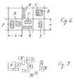
- FIG. 2 shows greatly enlarged a section of a screen printing, as it is on the substrate S after passing through the printing gap, for example, the FIG. 1a results.
- the surfaces of the printing form cylinders 1 and 2 are divided into grid cells in gridded cells, for example square grid cells, each with a length 1 measured in the circumferential direction of the relevant cylinder 1 or 2 and a width b measured parallel to the respective axis of rotation.
- the length 1 may, for example, 250 microns and the width b may for example also be 250 microns.
- Lines drawn to represent the raster cells 1 * b are of course of a virtual nature and are not present as such on the respective printing form cylinder 1 or 2; they are merely intended to symbolize the mathematical raster used to produce the printing forms.
- Part of the grid cells is with both Printing inks Y and B, another part each with only one of the inks Y and B and another part with none of these colors. As far as raster cells are occupied with both colors, no color coverage takes place.
- the inks Y and B are arranged in the respective grid cells exclusively side by side.
- On the printing form cylinder 1 only the inking locations designated Y are covered with the printing ink Y, the surface areas of the peripheral surface remaining around these inking areas Y are non-inking areas.
- the color assignment of the transfer cylinder 5 corresponds to the printed image shown. Due to the disjoint color assignment of the transfer cylinder 5, there can be no cleavage of one ink Y or B on the other printing forme cylinder 2 or 1 and in its inking, at least not in a practically relevant extent.
- the color points B of the transfer cylinder 5 roll only at the non-color points of the printing form cylinder 1 and the color points Y only at the non-color points of the printing forme cylinder 2, which reject each color.
- FIG. 2 shows an example of a color separation according to the invention for the printing inks yellow and black, Y and B, in principle, other color combinations can be collected on the transfer cylinder 5, for example, two bright colors such as the colors cyan and magenta, C and M.
- the screening refines it is advantageous if the screening refines, the grid cells a ⁇ b thus reduced and thus the distribution of the color points and non-color points on the respective printing forme cylinder is refined, for example, at most 200 microns or at most 100 microns for the length a and the width b the individual grid cells.
- FIG. 3 shows an alternative color separation again by way of example for the printing inks yellow and black, Y and B.
- the mutually separated inks Y and B occupy color points with a stochastic distribution. Such a distribution can be obtained for example by a frequency-modulated raster method.
- the color locations designated Y and B can each be composed of only a single or even a plurality of halftone dots of the respective printing ink Y or B.
- the respective inks can be used as an alternative to the example of FIGS. 2 and 3 explained color separation and each other at least partially overlapping on a common transfer cylinder 5 are stored.
- the combined with each other inks combined in accordance with their rheological properties.
- the ink that is deposited behind the printing gap as the first on the transfer cylinder 5, has a greater cohesion than the only then at least partially deposited on her further ink.
- the ink C has the greater cohesion.
- color separation therefore takes place only or only to a practically relevant extent within the printing ink M, while the printing ink C with the greater cohesion remains on the transfer cylinder 5.
- the ink applied first in Example C, further has a high adhesion to the outer peripheral surface of the transfer cylinder 5.
- the further printing ink in the example M, a sufficiently large adhesion to the outer free surface of the first applied ink C, so that cleavage neither at the interface between the transfer cylinder 5 and the first applied ink C still at the interface between the printing inks C and M takes place.
- FIG. 4 shows a printing arrangement with three printing columns, in which the substrate S successively at least on one side with four printing inks, in the embodiment M, C, B and Y, is printed.
- the arrangement on the opposite side of the substrate S can be the same as a mirror image.
- the web-shaped substrate S is first passed through two conventionally formed printing bridges and printed there successively with the inks M and C.
- the printing bridges for the printing inks M and C are arranged in a known manner to form an H printing unit.
- the inks C and M are distributed on the respective printing form cylinder 3 and 4 in a conventional manner in inking and non-inking, for example, as known from the autotypical screen printing ago.
- the substrate S is simultaneously printed with the remaining further printing inks, in the exemplary embodiment the inks Y and B.
- the color assignment of the printing form cylinder 1 and 2 is as in the example of FIGS. 2 and 3 explained so designed that the color points of a printing plate cylinder 1 or 2 come to lie on the transfer cylinder 5 and, accordingly, on the substrate S only in the range of non-ink spots of the other printing forme cylinder 2 or 1.
- the inks Y and B may be separated, and instead the remaining other inks, in the embodiment C and M, transferred to the substrate S via a common transfer cylinder 5, either with at least partial coverage and the rheological properties discussed herein, or alternatively in the US Pat explained color separation.
- FIG. 5 shows a printing arrangement with two printing columns, in which the web-shaped substrate S is printed on both sides each in four colors.
- the colors C and M are printed on both sides and in the second printing gap, the colors Y and B are also printed on both sides.
- the colors C and M can be deposited disjointly or almost disjointly in the context of the color separation according to the invention or in the context of rheological properties set according to the invention with at least partial coverage on the respective transfer cylinder 5 and from there onto the substrate S.
- the left and right printing units operate according to the same method.
- the two printing units of the rear printing unit in the conveying direction are preferably with the invention Operated color separation, but in principle can also be operated in the other process variant. Again, it is true that both printing units of this printing unit preferably work according to the same process variant.
- FIG. 6 shows a satellite printing unit with four printing columns in which the web-shaped substrate S is printed on both sides in four colors.
- the printing unit comprises two centrally arranged, non-printing impression cylinders 6, preferably steel cylinders, which each form two pressure gaps with two transfer cylinders 5.
- Each of the transfer cylinder 5 are each assigned two printing form cylinder, twice printing forme cylinder 1 and 2 for Y and B and twice printing forme cylinder 3 and 4 for C and M, the reference numerals as in the other examples only to distinguish the colors and the printing form cylinder 1-4 as such can be the same.
- the substrate wraps successively the two impression cylinders 6 and is printed on the one side and then on the other side first with the colors C and M and then with the colors Y and B when passing through the printing unit.
- both sides of the substrate S can be printed in four colors.
- the ink separation according to the invention is preferred for the color combination Y with B, as this reliably prevents the splitting back of ink onto the respective other printing forme cylinder and, in particular, saves ink.
- the pressure assemblies are preferably designed in tower construction, so the pressure gaps arranged so at least substantially vertically one above the other.
- the inking cylinders 1 to 4 are each individually assigned inking units not shown.
- the inking units may in particular be gap inking units, but alternatively, for example, nozzle systems may also be used.
- dampening units are additionally assigned to the printing forme cylinders 1 to 4.
Landscapes
- Engineering & Computer Science (AREA)
- Mechanical Engineering (AREA)
- Printing Methods (AREA)
Applications Claiming Priority (1)
| Application Number | Priority Date | Filing Date | Title |
|---|---|---|---|
| DE102008012385A DE102008012385A1 (de) | 2008-03-04 | 2008-03-04 | Offsetdruck mit reduziertem Farbauftrag |
Publications (2)
| Publication Number | Publication Date |
|---|---|
| EP2098375A2 true EP2098375A2 (fr) | 2009-09-09 |
| EP2098375A3 EP2098375A3 (fr) | 2011-10-12 |
Family
ID=40599974
Family Applications (1)
| Application Number | Title | Priority Date | Filing Date |
|---|---|---|---|
| EP09154264A Withdrawn EP2098375A3 (fr) | 2008-03-04 | 2009-03-04 | Impression offset ayant une application de couleur réduite |
Country Status (2)
| Country | Link |
|---|---|
| EP (1) | EP2098375A3 (fr) |
| DE (1) | DE102008012385A1 (fr) |
Cited By (1)
| Publication number | Priority date | Publication date | Assignee | Title |
|---|---|---|---|---|
| CN117360075A (zh) * | 2023-11-24 | 2024-01-09 | 广东环宇包装有限公司 | 一种彩色印刷机的控制方法、装置、终端以及存储介质 |
Families Citing this family (2)
| Publication number | Priority date | Publication date | Assignee | Title |
|---|---|---|---|---|
| DE102010003812A1 (de) | 2010-04-09 | 2011-10-13 | Koenig & Bauer Aktiengesellschaft | Bogendruckmaschine mit mindestens zwei Druckwerken |
| EP2388136B1 (fr) | 2010-05-19 | 2014-01-22 | WIFAG Maschinenfabrik AG | Elément d'impression combiné |
Citations (1)
| Publication number | Priority date | Publication date | Assignee | Title |
|---|---|---|---|---|
| EP0644048A2 (fr) | 1993-12-29 | 1995-03-22 | Maschinenfabrik Wifag | Machine d'impression rotative, avec des cylindres porte-blanchet et porte-clichés réunisen groupes de cylindres par paires |
Family Cites Families (6)
| Publication number | Priority date | Publication date | Assignee | Title |
|---|---|---|---|---|
| NL297506A (fr) * | 1963-09-25 | |||
| DE2323849B2 (de) * | 1973-05-11 | 1976-04-29 | Maschinenfabrik Augsburg-Nürnberg AG, 8900 Augsburg | Mehrfarben-nassoffset-rollen-rotationsdruckmaschine |
| DE3320141C2 (de) * | 1983-06-03 | 1986-07-03 | Harald 6070 Langen Küppers | Reproduktionsverfahren zur Herstellung mehrfarbiger Drucke |
| US4812899A (en) * | 1985-01-29 | 1989-03-14 | Harald Kueppers | Printing process where each incremental area is divided into a chromatic area and an achromatic area and wherein the achromatic areas are printed in black and white and the chromatic areas are printed in color sub-sections |
| US5469787A (en) * | 1994-03-15 | 1995-11-28 | Heath Custom Press, Inc. | Multi-color printing press |
| FR2745750B1 (fr) * | 1996-03-08 | 1998-04-30 | Oreal | Procede et machine d'impression pour la mise en oeuvre du procede et support ainsi imprime |
-
2008
- 2008-03-04 DE DE102008012385A patent/DE102008012385A1/de not_active Ceased
-
2009
- 2009-03-04 EP EP09154264A patent/EP2098375A3/fr not_active Withdrawn
Patent Citations (1)
| Publication number | Priority date | Publication date | Assignee | Title |
|---|---|---|---|---|
| EP0644048A2 (fr) | 1993-12-29 | 1995-03-22 | Maschinenfabrik Wifag | Machine d'impression rotative, avec des cylindres porte-blanchet et porte-clichés réunisen groupes de cylindres par paires |
Cited By (1)
| Publication number | Priority date | Publication date | Assignee | Title |
|---|---|---|---|---|
| CN117360075A (zh) * | 2023-11-24 | 2024-01-09 | 广东环宇包装有限公司 | 一种彩色印刷机的控制方法、装置、终端以及存储介质 |
Also Published As
| Publication number | Publication date |
|---|---|
| EP2098375A3 (fr) | 2011-10-12 |
| DE102008012385A1 (de) | 2009-09-10 |
Similar Documents
| Publication | Publication Date | Title |
|---|---|---|
| DD283971A5 (de) | Kombinierte bogenrotationsdruckmaschine fuer wertscheine, insbesondere banknoten | |
| DD283788A5 (de) | Rollendruckmaschine fuer den schoen- und widerdruck, insbesondere von banknoten | |
| DD209595A5 (de) | Mehrfarbenrotationsdruckmaschine | |
| DD218320A5 (de) | Mehrfarbenrotationsdruckmaschine zum gleichzeitigen schoen- und widerdruck | |
| DE3109964A1 (de) | "sammeldruck-rotationsmaschinendruckwerk fuer wertpapierdruck" | |
| EP0918640B1 (fr) | Presse d'impression de feuilles polychrome | |
| DE4422390B4 (de) | Doppelseiten-Bogen-Rotationsoffsetpresse | |
| DE102009002103B4 (de) | Druckmaschine und ein Verfahren zum Bedrucken eines bahnförmigen Bedruckstoffs | |
| EP1361049A2 (fr) | Unité d'impression | |
| DE102008012385A1 (de) | Offsetdruck mit reduziertem Farbauftrag | |
| EP1364780A2 (fr) | Unité d'impression | |
| DE2411691C3 (de) | Kombinierte Mehrfarben-Offset- und Stichdruckrotationsmaschine | |
| DE102008043908B4 (de) | Druckwerk | |
| DE102007046163B4 (de) | Druckeinheit für eine Rotationsdruckmaschine | |
| DE102006046521A1 (de) | Druckwerk einer Druckmaschine | |
| DE8224875U1 (de) | Farbwerk für Offsetdruckmaschinen | |
| EP1712355B1 (fr) | Unité d'impression d'une machine rotative d'impression | |
| DE3113407A1 (de) | "sammeldruck-rotationsmaschinendruckwerk fuer wertpapierdruck" | |
| DE202010006049U1 (de) | Rollendruckmaschine | |
| DE19740475A1 (de) | Druckende Zylinder in einer Rollenrotationsdruckmaschine mit zueinander versetzten Spannkanälen | |
| EP2388136B1 (fr) | Elément d'impression combiné | |
| DE102022128546A1 (de) | Druckvorrichtung für den Irisdruck | |
| DE102016109948A1 (de) | Separierter Antrieb von Walzen eines Farbwerkes in Koppelung mit einer dynamischen Farbgebungskorrektur | |
| DE102006051838A1 (de) | Verfahren zum Betreiben einer Druckmaschine sowie Druckmaschine | |
| DE202005011939U1 (de) | Bogendruckmaschine |
Legal Events
| Date | Code | Title | Description |
|---|---|---|---|
| PUAI | Public reference made under article 153(3) epc to a published international application that has entered the european phase |
Free format text: ORIGINAL CODE: 0009012 |
|
| AK | Designated contracting states |
Kind code of ref document: A2 Designated state(s): AT BE BG CH CY CZ DE DK EE ES FI FR GB GR HR HU IE IS IT LI LT LU LV MC MK MT NL NO PL PT RO SE SI SK TR |
|
| AX | Request for extension of the european patent |
Extension state: AL BA RS |
|
| REG | Reference to a national code |
Ref country code: DE Ref legal event code: R079 Free format text: PREVIOUS MAIN CLASS: B41M0001060000 Ipc: B41F0007080000 |
|
| RIC1 | Information provided on ipc code assigned before grant |
Ipc: B41F 17/00 20060101ALI20110524BHEP Ipc: B41F 7/12 20060101ALI20110524BHEP Ipc: B41M 1/10 20060101ALI20110524BHEP Ipc: B41M 1/06 20060101ALI20110524BHEP Ipc: B41M 1/20 20060101ALI20110524BHEP Ipc: B41F 7/08 20060101AFI20110524BHEP |
|
| PUAL | Search report despatched |
Free format text: ORIGINAL CODE: 0009013 |
|
| AK | Designated contracting states |
Kind code of ref document: A3 Designated state(s): AT BE BG CH CY CZ DE DK EE ES FI FR GB GR HR HU IE IS IT LI LT LU LV MC MK MT NL NO PL PT RO SE SI SK TR |
|
| AX | Request for extension of the european patent |
Extension state: AL BA RS |
|
| RIC1 | Information provided on ipc code assigned before grant |
Ipc: B41F 17/00 20060101ALI20110908BHEP Ipc: B41F 7/12 20060101ALI20110908BHEP Ipc: B41M 1/10 20060101ALI20110908BHEP Ipc: B41M 1/06 20060101ALI20110908BHEP Ipc: B41M 1/20 20060101ALI20110908BHEP Ipc: B41F 7/08 20060101AFI20110908BHEP |
|
| AKY | No designation fees paid | ||
| REG | Reference to a national code |
Ref country code: DE Ref legal event code: R108 |
|
| REG | Reference to a national code |
Ref country code: DE Ref legal event code: R108 Effective date: 20120620 |
|
| STAA | Information on the status of an ep patent application or granted ep patent |
Free format text: STATUS: THE APPLICATION IS DEEMED TO BE WITHDRAWN |
|
| 18D | Application deemed to be withdrawn |
Effective date: 20120413 |