EP2098665A1 - Fenêtre ou porte coulissante - Google Patents
Fenêtre ou porte coulissante Download PDFInfo
- Publication number
- EP2098665A1 EP2098665A1 EP08004122A EP08004122A EP2098665A1 EP 2098665 A1 EP2098665 A1 EP 2098665A1 EP 08004122 A EP08004122 A EP 08004122A EP 08004122 A EP08004122 A EP 08004122A EP 2098665 A1 EP2098665 A1 EP 2098665A1
- Authority
- EP
- European Patent Office
- Prior art keywords
- fitting
- carriage
- wing
- fitting arrangement
- door
- Prior art date
- Legal status (The legal status is an assumption and is not a legal conclusion. Google has not performed a legal analysis and makes no representation as to the accuracy of the status listed.)
- Granted
Links
Images



Classifications
-
- E—FIXED CONSTRUCTIONS
- E05—LOCKS; KEYS; WINDOW OR DOOR FITTINGS; SAFES
- E05D—HINGES OR SUSPENSION DEVICES FOR DOORS, WINDOWS OR WINGS
- E05D1/00—Pinless hinges; Substitutes for hinges
- E05D1/04—Pinless hinges; Substitutes for hinges with guide members shaped as circular arcs
-
- E—FIXED CONSTRUCTIONS
- E05—LOCKS; KEYS; WINDOW OR DOOR FITTINGS; SAFES
- E05D—HINGES OR SUSPENSION DEVICES FOR DOORS, WINDOWS OR WINGS
- E05D15/00—Suspension arrangements for wings
- E05D15/06—Suspension arrangements for wings for wings sliding horizontally more or less in their own plane
- E05D15/10—Suspension arrangements for wings for wings sliding horizontally more or less in their own plane movable out of one plane into a second parallel plane
- E05D15/1005—Suspension arrangements for wings for wings sliding horizontally more or less in their own plane movable out of one plane into a second parallel plane the wing being supported on arms movable in horizontal planes
- E05D15/1013—Suspension arrangements for wings for wings sliding horizontally more or less in their own plane movable out of one plane into a second parallel plane the wing being supported on arms movable in horizontal planes specially adapted for windows
-
- E—FIXED CONSTRUCTIONS
- E05—LOCKS; KEYS; WINDOW OR DOOR FITTINGS; SAFES
- E05D—HINGES OR SUSPENSION DEVICES FOR DOORS, WINDOWS OR WINGS
- E05D15/00—Suspension arrangements for wings
- E05D15/06—Suspension arrangements for wings for wings sliding horizontally more or less in their own plane
- E05D15/10—Suspension arrangements for wings for wings sliding horizontally more or less in their own plane movable out of one plane into a second parallel plane
- E05D15/1005—Suspension arrangements for wings for wings sliding horizontally more or less in their own plane movable out of one plane into a second parallel plane the wing being supported on arms movable in horizontal planes
- E05D15/1013—Suspension arrangements for wings for wings sliding horizontally more or less in their own plane movable out of one plane into a second parallel plane the wing being supported on arms movable in horizontal planes specially adapted for windows
- E05D15/1015—Suspension arrangements for wings for wings sliding horizontally more or less in their own plane movable out of one plane into a second parallel plane the wing being supported on arms movable in horizontal planes specially adapted for windows with an intermediate tilt position
-
- E—FIXED CONSTRUCTIONS
- E05—LOCKS; KEYS; WINDOW OR DOOR FITTINGS; SAFES
- E05D—HINGES OR SUSPENSION DEVICES FOR DOORS, WINDOWS OR WINGS
- E05D15/00—Suspension arrangements for wings
- E05D15/06—Suspension arrangements for wings for wings sliding horizontally more or less in their own plane
- E05D15/10—Suspension arrangements for wings for wings sliding horizontally more or less in their own plane movable out of one plane into a second parallel plane
- E05D2015/1028—Suspension arrangements for wings for wings sliding horizontally more or less in their own plane movable out of one plane into a second parallel plane with only the wing moving transversely
- E05D2015/1031—Suspension arrangements for wings for wings sliding horizontally more or less in their own plane movable out of one plane into a second parallel plane with only the wing moving transversely the wing supported on arms extending from the carriage
-
- E—FIXED CONSTRUCTIONS
- E05—LOCKS; KEYS; WINDOW OR DOOR FITTINGS; SAFES
- E05F—DEVICES FOR MOVING WINGS INTO OPEN OR CLOSED POSITION; CHECKS FOR WINGS; WING FITTINGS NOT OTHERWISE PROVIDED FOR, CONCERNED WITH THE FUNCTIONING OF THE WING
- E05F11/00—Man-operated mechanisms for operating wings, including those which also operate the fastening
- E05F11/02—Man-operated mechanisms for operating wings, including those which also operate the fastening for wings in general, e.g. fanlights
- E05F11/08—Man-operated mechanisms for operating wings, including those which also operate the fastening for wings in general, e.g. fanlights with longitudinally-moving bars guided, e.g. by pivoted links, in or on the frame
- E05F11/12—Mechanisms by which the bar shifts the wing
- E05F11/14—Mechanisms by which the bar shifts the wing directly, i.e. without links, shifting the wing, e.g. by rack and gear or pin and slot
- E05F11/145—Mechanisms by which the bar shifts the wing directly, i.e. without links, shifting the wing, e.g. by rack and gear or pin and slot by pin and slot
-
- E—FIXED CONSTRUCTIONS
- E05—LOCKS; KEYS; WINDOW OR DOOR FITTINGS; SAFES
- E05Y—INDEXING SCHEME ASSOCIATED WITH SUBCLASSES E05D AND E05F, RELATING TO CONSTRUCTION ELEMENTS, ELECTRIC CONTROL, POWER SUPPLY, POWER SIGNAL OR TRANSMISSION, USER INTERFACES, MOUNTING OR COUPLING, DETAILS, ACCESSORIES, AUXILIARY OPERATIONS NOT OTHERWISE PROVIDED FOR, APPLICATION THEREOF
- E05Y2900/00—Application of doors, windows, wings or fittings thereof
- E05Y2900/10—Application of doors, windows, wings or fittings thereof for buildings or parts thereof
- E05Y2900/13—Type of wing
- E05Y2900/132—Doors
-
- E—FIXED CONSTRUCTIONS
- E05—LOCKS; KEYS; WINDOW OR DOOR FITTINGS; SAFES
- E05Y—INDEXING SCHEME ASSOCIATED WITH SUBCLASSES E05D AND E05F, RELATING TO CONSTRUCTION ELEMENTS, ELECTRIC CONTROL, POWER SUPPLY, POWER SIGNAL OR TRANSMISSION, USER INTERFACES, MOUNTING OR COUPLING, DETAILS, ACCESSORIES, AUXILIARY OPERATIONS NOT OTHERWISE PROVIDED FOR, APPLICATION THEREOF
- E05Y2900/00—Application of doors, windows, wings or fittings thereof
- E05Y2900/10—Application of doors, windows, wings or fittings thereof for buildings or parts thereof
- E05Y2900/13—Type of wing
- E05Y2900/148—Windows
Definitions
- the invention relates to a fitting arrangement for a window, a door or the like.
- a fitting arrangement for a window, a door or the like.
- two relatively pivotable fitting parts wherein one of the fitting parts has a control cam and the other fitting part has two guide means spaced apart, which protrude into the control cam ,
- the invention further relates to a window, a door or the like.
- a window, a door or the like With a fixed frame and a pivotable at least about a horizontal pivot axis relative to the fixed frame or parallel off the fixed frame wings.
- control arm is provided which is articulated on one of the lower Ausstellarme, wherein also the locking receptacle on the carriage and the locking member are mounted on the control arm and the stationary stop cooperates in the sliding-Schinnedamba with the control arm.
- Such Arrangement is relatively unstable, since the articulated raising arms have a certain amount of play.
- a wing in a corner region can be pressed against a fixed frame or is not as far from the fixed frame as the other corner areas.
- From the AT 250208 is an opening device for tilting - swinging wings of windows, doors or the like with a horizontally above the wing between the fixed frame and wing arranged extension arm and provided between the wing and the extension arm, actuated by a linkage control arm, which is connected to the extension arm by a in a slot of the extension arm sliding connecting pin is connected, known.
- the control arm is provided with two guide pins which slide when tilting the wing by partially curved slots of the stay arm.
- the connecting pin simultaneously represents the pivot point or the pivot bearing for the pivoting movement of the arms relative to each other.
- the arrangement shown there is large building.
- the fixed by the connecting pin pivot is not fixed in the folded area.
- the system of the closed wing on the frame is ensured by mutually parallel slot sections and three pins or pins, wherein the connecting pin and a guide pin in a straight slot portion and a guide pin in the parallel straight slot portion are arranged.
- Object of the present invention is therefore to provide a simplified, small-scale fitting arrangement for stabilizing use in a sliding window or a sliding door.
- the guide means and the control cam are moved relative to each other.
- This arrangement is self-blocking when the wing is closed. A partial, unwanted opening of the wing is prevented, as is practically excluded by the two guide means game between the tabs.
- the arrangement causes a forced control of the movement of the wing. It can be provided to arrange the control cam on the fixed frame side / trolley side fitting part and to provide the guide means on the fitting component pivotable thereto.
- the kinematic reversal is also conceivable, namely to arrange the guide means on the fixed frame side / trolley side fitting part and the control cam on the pivotal fitting part.
- the virtual pivot point may preferably be outside the fitting arrangement. By this measure it can be ensured that a sliding door is turned off the frame without being blocked by the frame.
- control cam has a constant radius.
- control cam has at least two sections with different radius.
- a pivoting movement about two different pivot points which can both be outside the fitting arrangement, can be realized.
- different inclinations of one fitting part relative to the other fitting part can be realized by this measure.
- one of the fitting parts is designed as a fixed to a carriage or to be fastened to the fixed enclosure fitting part.
- At least one guide means or bolt is eccentrically adjustable.
- an adaptation or adjustment of the fitting arrangement can take place in particular also in the installed state.
- a window, a door or the like In the context of the invention also falls a window, a door or the like.
- a concealed fitting is provided, and a fitting arrangement according to the invention described above is provided.
- a fitting arrangement according to the invention it is ensured that when the wing is pressed against only one point, all other areas of the wing reliably abut against the frame as well.
- a forced control is carried out by a movement initiation by means of the wing.
- At least one, preferably at least two fitting arrangements are arranged in the upper region of a sliding door or a sliding window. If it is provided that the sash of the sliding window or the sliding door can be transferred to a tilt-open state, that is pivotable about a lower horizontal axis, it can be ensured by the fitting arrangement in the upper region of the sliding window or the sliding door that the wing evenly along its entire length and no play arises.
- a curve realized on the carriage in the lower region of the sliding window or the sliding door can be simulated by the fitting arrangement according to the invention in a simple manner, which describes the wing when parking from the fixed enclosure. This applies both in the event that the diegelkipp- as well as Schiebiebeöffenbar. In the latter case, the wing is parked parallel to the fixed frame and then moved.
- At least one carriage is provided with a fitting arrangement according to the invention. It is particularly advantageous if at least two carriages are provided with a fitting arrangement according to the invention, so that a uniform parking in the lower region of the sliding leaf is ensured.
- a fitting arrangement according to the invention is provided both in the upper window or door area and on at least one carriage, wherein the control cams of the upper fitting arrangement and the fitting arrangement on the carriage are bent in opposite directions.
- the virtual pivot lies on top and bottom on different sides of the frame-side fitting part.
- FIG. 1 a top view of a sliding door 10 is shown.
- the sliding door 10 has a fixed field 11 and a (sliding) wing 12.
- the wing 12 is pushed over the fixed field 11.
- the wing 12 is connected at the bottom with two carriages 13, 14.
- Above two Ausstell Rhein 15, 16 are provided.
- the wing 12 can be unlocked in the upper area by a corresponding operating device 17, so that the wing 12 can be parked at the top. This means that the wing 12 can be tilted open.
- the control element 17 and the wing 12 can be parked in the lower area and then the so parked parallel wing 12 can be moved over the fixed field 11.
- FIG. 2 a side view of the sliding door 10 is shown.
- On the fixed frame 20 are below a running rail 21 and above a slide rail 22 arranged.
- the wing 12 is supported by the carriages 13, 14 on the running rail 21.
- In the upper part of the wing 12 is slidably connected to the slide rail 22 via the Ausstell Rheinen 15, 16.
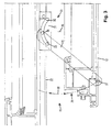
- FIG. 3 a detail of the upper left handoff 15 is shown.
- This comprises a fitting arrangement 30, which has a first relative to the slide rail 22 displaceable fitting part 31 with a control cam 32.
- This control cam 32 two trained as a bolt guide means 33, 34 of a second fitting part 35 are guided.
- the control cam 32, together with the guide means 33, 34 is a rotary bearing, which has a pivot point 36.
- the pivot point 36 is located outside of the fitting part 31.
- the fitting 35 is pivotally connected via a rotary joint 37 with the wing 12. When closing and opening the wing, the fitting 35 moves with its one end in the double arrow direction 38, so that the rotary joint 37 and the pivot point 37 moves along the curve 39. Due to the interaction of the fitting parts 31, 35, a positive control during opening and closing of the wing 12 is realized.
- the virtual pivot point 36 is the center of the control cam 32 and at the same time the pivot point for the movement of the pivot point 37 along the curve 39.
- the movement is immediately positively controlled due to the interaction of the guide means 33, 34 with the control cam 12. There is no game and the wing 12 does not flutter.
- the distance of the pivot point 37 from the virtual pivot point 36 determines the desired opening of the wing 12. In particular, thereby desired maximum opening angle can be adjusted.
- the right upper Ausstell ST 16 is shown, which also has a fitting assembly 30.
- the wing 12 is shown in its open position and designated as 12 'in its closed position.
- the fitting assembly 30 is designed so that the wing 12 does not abut against the fixed frame 20 with its corner 40 when opening and closing.
- the fitting assembly 30 is thus designed so that the wing, as can be seen from the curve 39, initially substantially only bringsell from the fixed frame 20 before he performs a movement to the right.
- the fitting 31 sliding along the rail 22.
- the fitting part 31 is locked with respect to the rail 22, for example when only a tilting opening of the wing 12 is desired.
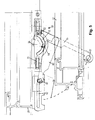
- a fitting arrangement 50 is shown, which is arranged on the lower left carriage 13.
- the fitting arrangement 50 has a first fitting part 51, which is provided for mounting on the carriage 13.
- the first fitting part 51 has a control cam 52.
- the control cam 52 are two trained as a bolt guide means 53, 54 of a second fitting part 55 is guided.
- the control cam 52, together with the guide means 53, 54 is a pivot bearing, which has a (virtual) pivot point 56.
- the virtual fulcrum 56 lies outside the fitting part 51.
- the control cam 52 is curved in opposite directions.
- the virtual pivot point 56 is located on the other side of the first fitting part 51 than in the fitting assembly 50.
- the virtual pivot point 56 is the center of the control cam 52 and at the same time the pivot point for the movement of the pivot point 57, which represents the connection of the second fitting part 55 with the wing 12, along the curve 59.
- the fitting 55 is further connected via a link 60 to the first fitting part 51.
- the handlebar 60 is pivotally mounted to the fitting 55. Furthermore, it is guided with a bolt 61 in a guide 62 of the first fitting part 51. In the position shown, the bolt 61 is locked in a bent end of the guide 62 and thus holds the fitting 55 in the position shown.
- the wing 12 is thus fixed at a distance from the frame 20 and can be moved parallel to the frame 20.
- the bolt 61 is displaced in the guide 62 from the position shown.
- the wing 12 can thereby be approximated to the frame 20. During this movement of the wing 12, the carriage 13 can move to the right.
- FIG. 6 is also a fitting assembly 50 is shown, with the difference that no handlebar 60 is provided. Otherwise corresponds to the fitting assembly 50 in the FIG. 5 shown.
- the fitting assembly 50 is designed so that the wing 12, which is shown with the reference numeral 12 in its open position and the reference numeral 12 'in its closed position, without being able to strike the fixed frame 20 can be opened and closed. By the fitting assembly 50, therefore, the kinematics of the wing 12 is determined.
- top and bottom of the wing 12th Fitting arrangements 30 and 50 are provided, there is a complete positive control of the wing 12. It is sufficient to fix the wing in its parked position from the frame by the handlebar 60.
- the fitting assemblies 30, 50 at the other locations of the wing 12 a movement of the wing 12 is inhibited in the direction of the frame. He can not be pressed against the frame 20 without the handlebar 60 is released from its locking with the fitting 51.
Landscapes
- Engineering & Computer Science (AREA)
- Mechanical Engineering (AREA)
- Power-Operated Mechanisms For Wings (AREA)
- Closing And Opening Devices For Wings, And Checks For Wings (AREA)
Priority Applications (2)
| Application Number | Priority Date | Filing Date | Title |
|---|---|---|---|
| PL08004122T PL2098665T3 (pl) | 2008-03-06 | 2008-03-06 | Okno przesuwne bądź drzwi przesuwne |
| EP08004122.1A EP2098665B1 (fr) | 2008-03-06 | 2008-03-06 | Fenêtre ou porte coulissante |
Applications Claiming Priority (1)
| Application Number | Priority Date | Filing Date | Title |
|---|---|---|---|
| EP08004122.1A EP2098665B1 (fr) | 2008-03-06 | 2008-03-06 | Fenêtre ou porte coulissante |
Publications (2)
| Publication Number | Publication Date |
|---|---|
| EP2098665A1 true EP2098665A1 (fr) | 2009-09-09 |
| EP2098665B1 EP2098665B1 (fr) | 2013-12-25 |
Family
ID=39677332
Family Applications (1)
| Application Number | Title | Priority Date | Filing Date |
|---|---|---|---|
| EP08004122.1A Not-in-force EP2098665B1 (fr) | 2008-03-06 | 2008-03-06 | Fenêtre ou porte coulissante |
Country Status (2)
| Country | Link |
|---|---|
| EP (1) | EP2098665B1 (fr) |
| PL (1) | PL2098665T3 (fr) |
Citations (4)
| Publication number | Priority date | Publication date | Assignee | Title |
|---|---|---|---|---|
| DE959353C (de) * | 1955-01-15 | 1957-03-07 | Ver Baubeschlag Gretsch Co | Ausstellvorrichtung fuer wahlweise um eine lotrechte Achse schwenkbare oder um eine waagerechte Achse kippbare Fluegel von Fenstern, Tueren od. dgl. |
| AT250208B (de) | 1963-12-18 | 1966-10-25 | Wilhelm Weber | Ausstellvorrichtung für Kipp-Schwenkflügel von Fenstern, Türen od. dgl. |
| EP0103725A2 (fr) * | 1982-09-18 | 1984-03-28 | Gretsch-Unitas GmbH Baubeschläge | Ferrure pour un battant de fenêtre, porte ou similaire, qui peut au moins être déplacée dans un plan parallèle |
| US6292981B1 (en) * | 1999-04-14 | 2001-09-25 | Southco, Inc. | Crescent hinge |
-
2008
- 2008-03-06 EP EP08004122.1A patent/EP2098665B1/fr not_active Not-in-force
- 2008-03-06 PL PL08004122T patent/PL2098665T3/pl unknown
Patent Citations (5)
| Publication number | Priority date | Publication date | Assignee | Title |
|---|---|---|---|---|
| DE959353C (de) * | 1955-01-15 | 1957-03-07 | Ver Baubeschlag Gretsch Co | Ausstellvorrichtung fuer wahlweise um eine lotrechte Achse schwenkbare oder um eine waagerechte Achse kippbare Fluegel von Fenstern, Tueren od. dgl. |
| AT250208B (de) | 1963-12-18 | 1966-10-25 | Wilhelm Weber | Ausstellvorrichtung für Kipp-Schwenkflügel von Fenstern, Türen od. dgl. |
| EP0103725A2 (fr) * | 1982-09-18 | 1984-03-28 | Gretsch-Unitas GmbH Baubeschläge | Ferrure pour un battant de fenêtre, porte ou similaire, qui peut au moins être déplacée dans un plan parallèle |
| EP0103725B1 (fr) | 1982-09-18 | 1988-12-07 | Gretsch-Unitas GmbH Baubeschläge | Ferrure pour un battant de fenêtre, porte ou similaire, qui peut au moins être déplacée dans un plan parallèle |
| US6292981B1 (en) * | 1999-04-14 | 2001-09-25 | Southco, Inc. | Crescent hinge |
Also Published As
| Publication number | Publication date |
|---|---|
| EP2098665B1 (fr) | 2013-12-25 |
| PL2098665T3 (pl) | 2014-05-30 |
Similar Documents
| Publication | Publication Date | Title |
|---|---|---|
| EP1959080B1 (fr) | Butée de battant mobile de fenêtre ou de porte | |
| EP2828460B1 (fr) | Ferrure de fenetre ou porte avec un battant deplaceable vers un plan parallèle et coulissable horizontalement dans ledit plan parallèle | |
| EP3969703B1 (fr) | Système de guidage pour guider au moins un battant de porte | |
| EP2540941A2 (fr) | Articulation cachée pour une porte ou des composants similaires | |
| EP0515931A1 (fr) | Ferrure pour battant oscillo-battants | |
| DE68903724T2 (de) | Beschlag fuer tuer, fenster oder dergleichen. | |
| DE3041399A1 (de) | Fenster kipp und spaltkipp | |
| EP3060736B1 (fr) | Ferrure pour fenêtres, portes ou similaires | |
| EP3175068B1 (fr) | Système de ferrure | |
| DE102011085177B4 (de) | Antriebssystem für ein KFZ-Dachsystem | |
| DE2451556A1 (de) | Feststellvorrichtung zur oeffnungsbegrenzung von kipp- und klappfluegeln, insbesondere kipp-schwenkfluegeln, an fenstern, tueren o.dgl. | |
| EP0096744A2 (fr) | Ferrure pour battant oscillo-battant | |
| WO2003046324A1 (fr) | Element de battant de porte mobile et pivotant | |
| EP0531626B1 (fr) | Ferrure, en particulier pour des battants étant basculés et déplacés d'un plan vers un deuxième plan parallèle | |
| EP0905343B1 (fr) | Agencement de fenêtre ou de porte | |
| WO2010127718A1 (fr) | Ferrure | |
| DE102008028598B4 (de) | Insektenschutztür | |
| EP2098665B1 (fr) | Fenêtre ou porte coulissante | |
| EP1614844A2 (fr) | Dispositif d'articulation | |
| EP1581712B1 (fr) | Unite d'armature pour fenetre ou porte | |
| EP0270748A2 (fr) | Dispositif d'ouverture d'un panneau de fenêtre, porte ou similaire | |
| EP1234942B1 (fr) | Ferrure pour une porte, une fenêtre ou similaire | |
| EP1437475A2 (fr) | Fenêtre ou porte avec dispositif d'entraínement | |
| EP1788175A1 (fr) | Assemblage de pattes pour fenêtres, portes et similaires | |
| DE10300654A1 (de) | Fenster oder Tür mit Antriebsvorrichtung |
Legal Events
| Date | Code | Title | Description |
|---|---|---|---|
| PUAI | Public reference made under article 153(3) epc to a published international application that has entered the european phase |
Free format text: ORIGINAL CODE: 0009012 |
|
| AK | Designated contracting states |
Kind code of ref document: A1 Designated state(s): AT BE BG CH CY CZ DE DK EE ES FI FR GB GR HR HU IE IS IT LI LT LU LV MC MT NL NO PL PT RO SE SI SK TR |
|
| AX | Request for extension of the european patent |
Extension state: AL BA MK RS |
|
| 17P | Request for examination filed |
Effective date: 20090917 |
|
| 17Q | First examination report despatched |
Effective date: 20091102 |
|
| AKX | Designation fees paid |
Designated state(s): AT BE BG CH CY CZ DE DK EE ES FI FR GB GR HR HU IE IS IT LI LT LU LV MC MT NL NO PL PT RO SE SI SK TR |
|
| GRAP | Despatch of communication of intention to grant a patent |
Free format text: ORIGINAL CODE: EPIDOSNIGR1 |
|
| INTG | Intention to grant announced |
Effective date: 20130802 |
|
| GRAS | Grant fee paid |
Free format text: ORIGINAL CODE: EPIDOSNIGR3 |
|
| GRAA | (expected) grant |
Free format text: ORIGINAL CODE: 0009210 |
|
| AK | Designated contracting states |
Kind code of ref document: B1 Designated state(s): AT BE BG CH CY CZ DE DK EE ES FI FR GB GR HR HU IE IS IT LI LT LU LV MC MT NL NO PL PT RO SE SI SK TR |
|
| REG | Reference to a national code |
Ref country code: GB Ref legal event code: FG4D Free format text: NOT ENGLISH |
|
| REG | Reference to a national code |
Ref country code: CH Ref legal event code: EP |
|
| REG | Reference to a national code |
Ref country code: AT Ref legal event code: REF Ref document number: 646761 Country of ref document: AT Kind code of ref document: T Effective date: 20140115 |
|
| REG | Reference to a national code |
Ref country code: IE Ref legal event code: FG4D Free format text: LANGUAGE OF EP DOCUMENT: GERMAN |
|
| REG | Reference to a national code |
Ref country code: DE Ref legal event code: R096 Ref document number: 502008011115 Country of ref document: DE Effective date: 20140213 |
|
| PG25 | Lapsed in a contracting state [announced via postgrant information from national office to epo] |
Ref country code: HR Free format text: LAPSE BECAUSE OF FAILURE TO SUBMIT A TRANSLATION OF THE DESCRIPTION OR TO PAY THE FEE WITHIN THE PRESCRIBED TIME-LIMIT Effective date: 20131225 Ref country code: FI Free format text: LAPSE BECAUSE OF FAILURE TO SUBMIT A TRANSLATION OF THE DESCRIPTION OR TO PAY THE FEE WITHIN THE PRESCRIBED TIME-LIMIT Effective date: 20131225 Ref country code: LT Free format text: LAPSE BECAUSE OF FAILURE TO SUBMIT A TRANSLATION OF THE DESCRIPTION OR TO PAY THE FEE WITHIN THE PRESCRIBED TIME-LIMIT Effective date: 20131225 Ref country code: SE Free format text: LAPSE BECAUSE OF FAILURE TO SUBMIT A TRANSLATION OF THE DESCRIPTION OR TO PAY THE FEE WITHIN THE PRESCRIBED TIME-LIMIT Effective date: 20131225 Ref country code: NO Free format text: LAPSE BECAUSE OF FAILURE TO SUBMIT A TRANSLATION OF THE DESCRIPTION OR TO PAY THE FEE WITHIN THE PRESCRIBED TIME-LIMIT Effective date: 20140325 |
|
| REG | Reference to a national code |
Ref country code: NL Ref legal event code: VDEP Effective date: 20131225 |
|
| REG | Reference to a national code |
Ref country code: LT Ref legal event code: MG4D |
|
| PG25 | Lapsed in a contracting state [announced via postgrant information from national office to epo] |
Ref country code: LV Free format text: LAPSE BECAUSE OF FAILURE TO SUBMIT A TRANSLATION OF THE DESCRIPTION OR TO PAY THE FEE WITHIN THE PRESCRIBED TIME-LIMIT Effective date: 20131225 |
|
| REG | Reference to a national code |
Ref country code: PL Ref legal event code: T3 |
|
| PG25 | Lapsed in a contracting state [announced via postgrant information from national office to epo] |
Ref country code: IS Free format text: LAPSE BECAUSE OF FAILURE TO SUBMIT A TRANSLATION OF THE DESCRIPTION OR TO PAY THE FEE WITHIN THE PRESCRIBED TIME-LIMIT Effective date: 20140425 Ref country code: EE Free format text: LAPSE BECAUSE OF FAILURE TO SUBMIT A TRANSLATION OF THE DESCRIPTION OR TO PAY THE FEE WITHIN THE PRESCRIBED TIME-LIMIT Effective date: 20131225 |
|
| PG25 | Lapsed in a contracting state [announced via postgrant information from national office to epo] |
Ref country code: PT Free format text: LAPSE BECAUSE OF FAILURE TO SUBMIT A TRANSLATION OF THE DESCRIPTION OR TO PAY THE FEE WITHIN THE PRESCRIBED TIME-LIMIT Effective date: 20140428 Ref country code: RO Free format text: LAPSE BECAUSE OF FAILURE TO SUBMIT A TRANSLATION OF THE DESCRIPTION OR TO PAY THE FEE WITHIN THE PRESCRIBED TIME-LIMIT Effective date: 20131225 Ref country code: NL Free format text: LAPSE BECAUSE OF FAILURE TO SUBMIT A TRANSLATION OF THE DESCRIPTION OR TO PAY THE FEE WITHIN THE PRESCRIBED TIME-LIMIT Effective date: 20131225 Ref country code: CZ Free format text: LAPSE BECAUSE OF FAILURE TO SUBMIT A TRANSLATION OF THE DESCRIPTION OR TO PAY THE FEE WITHIN THE PRESCRIBED TIME-LIMIT Effective date: 20131225 Ref country code: ES Free format text: LAPSE BECAUSE OF FAILURE TO SUBMIT A TRANSLATION OF THE DESCRIPTION OR TO PAY THE FEE WITHIN THE PRESCRIBED TIME-LIMIT Effective date: 20131225 Ref country code: CY Free format text: LAPSE BECAUSE OF FAILURE TO SUBMIT A TRANSLATION OF THE DESCRIPTION OR TO PAY THE FEE WITHIN THE PRESCRIBED TIME-LIMIT Effective date: 20131225 Ref country code: SK Free format text: LAPSE BECAUSE OF FAILURE TO SUBMIT A TRANSLATION OF THE DESCRIPTION OR TO PAY THE FEE WITHIN THE PRESCRIBED TIME-LIMIT Effective date: 20131225 |
|
| REG | Reference to a national code |
Ref country code: DE Ref legal event code: R097 Ref document number: 502008011115 Country of ref document: DE |
|
| PG25 | Lapsed in a contracting state [announced via postgrant information from national office to epo] |
Ref country code: LU Free format text: LAPSE BECAUSE OF FAILURE TO SUBMIT A TRANSLATION OF THE DESCRIPTION OR TO PAY THE FEE WITHIN THE PRESCRIBED TIME-LIMIT Effective date: 20140306 Ref country code: DK Free format text: LAPSE BECAUSE OF FAILURE TO SUBMIT A TRANSLATION OF THE DESCRIPTION OR TO PAY THE FEE WITHIN THE PRESCRIBED TIME-LIMIT Effective date: 20131225 |
|
| PLBE | No opposition filed within time limit |
Free format text: ORIGINAL CODE: 0009261 |
|
| STAA | Information on the status of an ep patent application or granted ep patent |
Free format text: STATUS: NO OPPOSITION FILED WITHIN TIME LIMIT |
|
| 26N | No opposition filed |
Effective date: 20140926 |
|
| REG | Reference to a national code |
Ref country code: IE Ref legal event code: MM4A |
|
| REG | Reference to a national code |
Ref country code: DE Ref legal event code: R097 Ref document number: 502008011115 Country of ref document: DE Effective date: 20140926 |
|
| PG25 | Lapsed in a contracting state [announced via postgrant information from national office to epo] |
Ref country code: IE Free format text: LAPSE BECAUSE OF NON-PAYMENT OF DUE FEES Effective date: 20140306 |
|
| PG25 | Lapsed in a contracting state [announced via postgrant information from national office to epo] |
Ref country code: SI Free format text: LAPSE BECAUSE OF FAILURE TO SUBMIT A TRANSLATION OF THE DESCRIPTION OR TO PAY THE FEE WITHIN THE PRESCRIBED TIME-LIMIT Effective date: 20131225 |
|
| PG25 | Lapsed in a contracting state [announced via postgrant information from national office to epo] |
Ref country code: MT Free format text: LAPSE BECAUSE OF FAILURE TO SUBMIT A TRANSLATION OF THE DESCRIPTION OR TO PAY THE FEE WITHIN THE PRESCRIBED TIME-LIMIT Effective date: 20131225 |
|
| REG | Reference to a national code |
Ref country code: FR Ref legal event code: PLFP Year of fee payment: 9 |
|
| PGFP | Annual fee paid to national office [announced via postgrant information from national office to epo] |
Ref country code: TR Payment date: 20160225 Year of fee payment: 9 Ref country code: CH Payment date: 20160322 Year of fee payment: 9 |
|
| PG25 | Lapsed in a contracting state [announced via postgrant information from national office to epo] |
Ref country code: BG Free format text: LAPSE BECAUSE OF FAILURE TO SUBMIT A TRANSLATION OF THE DESCRIPTION OR TO PAY THE FEE WITHIN THE PRESCRIBED TIME-LIMIT Effective date: 20131225 Ref country code: MC Free format text: LAPSE BECAUSE OF FAILURE TO SUBMIT A TRANSLATION OF THE DESCRIPTION OR TO PAY THE FEE WITHIN THE PRESCRIBED TIME-LIMIT Effective date: 20131225 |
|
| PGFP | Annual fee paid to national office [announced via postgrant information from national office to epo] |
Ref country code: FR Payment date: 20160322 Year of fee payment: 9 Ref country code: PL Payment date: 20160225 Year of fee payment: 9 Ref country code: GB Payment date: 20160322 Year of fee payment: 9 |
|
| PG25 | Lapsed in a contracting state [announced via postgrant information from national office to epo] |
Ref country code: GR Free format text: LAPSE BECAUSE OF FAILURE TO SUBMIT A TRANSLATION OF THE DESCRIPTION OR TO PAY THE FEE WITHIN THE PRESCRIBED TIME-LIMIT Effective date: 20131225 Ref country code: IT Free format text: LAPSE BECAUSE OF FAILURE TO SUBMIT A TRANSLATION OF THE DESCRIPTION OR TO PAY THE FEE WITHIN THE PRESCRIBED TIME-LIMIT Effective date: 20131225 |
|
| PG25 | Lapsed in a contracting state [announced via postgrant information from national office to epo] |
Ref country code: BE Free format text: LAPSE BECAUSE OF FAILURE TO SUBMIT A TRANSLATION OF THE DESCRIPTION OR TO PAY THE FEE WITHIN THE PRESCRIBED TIME-LIMIT Effective date: 20140331 Ref country code: HU Free format text: LAPSE BECAUSE OF FAILURE TO SUBMIT A TRANSLATION OF THE DESCRIPTION OR TO PAY THE FEE WITHIN THE PRESCRIBED TIME-LIMIT; INVALID AB INITIO Effective date: 20080306 |
|
| PGFP | Annual fee paid to national office [announced via postgrant information from national office to epo] |
Ref country code: AT Payment date: 20170322 Year of fee payment: 10 |
|
| REG | Reference to a national code |
Ref country code: CH Ref legal event code: PL |
|
| GBPC | Gb: european patent ceased through non-payment of renewal fee |
Effective date: 20170306 |
|
| REG | Reference to a national code |
Ref country code: FR Ref legal event code: ST Effective date: 20171130 |
|
| PG25 | Lapsed in a contracting state [announced via postgrant information from national office to epo] |
Ref country code: FR Free format text: LAPSE BECAUSE OF NON-PAYMENT OF DUE FEES Effective date: 20170331 |
|
| PG25 | Lapsed in a contracting state [announced via postgrant information from national office to epo] |
Ref country code: CH Free format text: LAPSE BECAUSE OF NON-PAYMENT OF DUE FEES Effective date: 20170331 Ref country code: GB Free format text: LAPSE BECAUSE OF NON-PAYMENT OF DUE FEES Effective date: 20170306 Ref country code: LI Free format text: LAPSE BECAUSE OF NON-PAYMENT OF DUE FEES Effective date: 20170331 |
|
| PGFP | Annual fee paid to national office [announced via postgrant information from national office to epo] |
Ref country code: DE Payment date: 20180324 Year of fee payment: 11 |
|
| PG25 | Lapsed in a contracting state [announced via postgrant information from national office to epo] |
Ref country code: PL Free format text: LAPSE BECAUSE OF NON-PAYMENT OF DUE FEES Effective date: 20170306 |
|
| REG | Reference to a national code |
Ref country code: AT Ref legal event code: MM01 Ref document number: 646761 Country of ref document: AT Kind code of ref document: T Effective date: 20180306 |
|
| PG25 | Lapsed in a contracting state [announced via postgrant information from national office to epo] |
Ref country code: AT Free format text: LAPSE BECAUSE OF NON-PAYMENT OF DUE FEES Effective date: 20180306 |
|
| REG | Reference to a national code |
Ref country code: DE Ref legal event code: R119 Ref document number: 502008011115 Country of ref document: DE |
|
| PG25 | Lapsed in a contracting state [announced via postgrant information from national office to epo] |
Ref country code: DE Free format text: LAPSE BECAUSE OF NON-PAYMENT OF DUE FEES Effective date: 20191001 |
|
| PG25 | Lapsed in a contracting state [announced via postgrant information from national office to epo] |
Ref country code: TR Free format text: LAPSE BECAUSE OF NON-PAYMENT OF DUE FEES Effective date: 20170306 |