EP2098811B1 - Tunnel de séchage pour sécher des ébauches, doté d'ouvertures d'air agencées de manière opposée et avec un écart transversal, et module de tunnel pour un tunnel de séchage - Google Patents
Tunnel de séchage pour sécher des ébauches, doté d'ouvertures d'air agencées de manière opposée et avec un écart transversal, et module de tunnel pour un tunnel de séchage Download PDFInfo
- Publication number
- EP2098811B1 EP2098811B1 EP09154501.2A EP09154501A EP2098811B1 EP 2098811 B1 EP2098811 B1 EP 2098811B1 EP 09154501 A EP09154501 A EP 09154501A EP 2098811 B1 EP2098811 B1 EP 2098811B1
- Authority
- EP
- European Patent Office
- Prior art keywords
- tunnel
- air
- conveying
- drying
- passage
- Prior art date
- Legal status (The legal status is an assumption and is not a legal conclusion. Google has not performed a legal analysis and makes no representation as to the accuracy of the status listed.)
- Active
Links
Images


Classifications
-
- F—MECHANICAL ENGINEERING; LIGHTING; HEATING; WEAPONS; BLASTING
- F26—DRYING
- F26B—DRYING SOLID MATERIALS OR OBJECTS BY REMOVING LIQUID THEREFROM
- F26B15/00—Machines or apparatus for drying objects with progressive movement; Machines or apparatus with progressive movement for drying batches of material in compact form
- F26B15/10—Machines or apparatus for drying objects with progressive movement; Machines or apparatus with progressive movement for drying batches of material in compact form with movement in a path composed of one or more straight lines, e.g. compound, the movement being in alternate horizontal and vertical directions
-
- B—PERFORMING OPERATIONS; TRANSPORTING
- B28—WORKING CEMENT, CLAY, OR STONE
- B28B—SHAPING CLAY OR OTHER CERAMIC COMPOSITIONS; SHAPING SLAG; SHAPING MIXTURES CONTAINING CEMENTITIOUS MATERIAL, e.g. PLASTER
- B28B11/00—Apparatus or processes for treating or working the shaped or preshaped articles
- B28B11/24—Apparatus or processes for treating or working the shaped or preshaped articles for curing, setting or hardening
- B28B11/243—Setting, e.g. drying, dehydrating or firing ceramic articles
-
- F—MECHANICAL ENGINEERING; LIGHTING; HEATING; WEAPONS; BLASTING
- F26—DRYING
- F26B—DRYING SOLID MATERIALS OR OBJECTS BY REMOVING LIQUID THEREFROM
- F26B15/00—Machines or apparatus for drying objects with progressive movement; Machines or apparatus with progressive movement for drying batches of material in compact form
- F26B15/10—Machines or apparatus for drying objects with progressive movement; Machines or apparatus with progressive movement for drying batches of material in compact form with movement in a path composed of one or more straight lines, e.g. compound, the movement being in alternate horizontal and vertical directions
- F26B15/12—Machines or apparatus for drying objects with progressive movement; Machines or apparatus with progressive movement for drying batches of material in compact form with movement in a path composed of one or more straight lines, e.g. compound, the movement being in alternate horizontal and vertical directions the lines being all horizontal or slightly inclined
- F26B15/14—Machines or apparatus for drying objects with progressive movement; Machines or apparatus with progressive movement for drying batches of material in compact form with movement in a path composed of one or more straight lines, e.g. compound, the movement being in alternate horizontal and vertical directions the lines being all horizontal or slightly inclined the objects or batches of materials being carried by trays or racks or receptacles, which may be connected to endless chains or belts
-
- F—MECHANICAL ENGINEERING; LIGHTING; HEATING; WEAPONS; BLASTING
- F26—DRYING
- F26B—DRYING SOLID MATERIALS OR OBJECTS BY REMOVING LIQUID THEREFROM
- F26B21/00—Arrangements for supplying or controlling air or other gases for drying solid materials or objects
- F26B21/20—Circulating air or gases in closed cycles, e.g. wholly within the drying enclosure
- F26B21/25—Circulating air or gases in closed cycles, e.g. wholly within the drying enclosure partly outside the drying enclosure
-
- F—MECHANICAL ENGINEERING; LIGHTING; HEATING; WEAPONS; BLASTING
- F26—DRYING
- F26B—DRYING SOLID MATERIALS OR OBJECTS BY REMOVING LIQUID THEREFROM
- F26B2210/00—Drying processes and machines for solid objects characterised by the specific requirements of the drying goods
- F26B2210/02—Ceramic articles or ceramic semi-finished articles
Definitions
- the invention relates to a tunnel dryer for drying moldings of ceramic or similar material, in particular of plate-shaped moldings, for example facade panels, tiles or roof tiles.
- Tunnel dryers of this type are introduced and known in various constructions in the ceramic industry and in the building materials industry.
- From the EP 0218733 A2 is a rapid drying process for the rapid drying of ceramic parts to be fired, and an apparatus for carrying out the process in the form of a continuous drying oven known.
- the drying takes place in three stages. First stage: heat supply in a moderately ventilated closed room. Second stage: Evacuation of the room to about 500 mbar (380 Torr) and generating highly turbulent air flow conditions. Third stage: Stop further air supply and evacuate to 60 mbar (45 Torr). Alternatively, a two-stage drying in two different drying containers is proposed.
- DE 40 02 643 C2 is a continuous dryer for drying ceramic products, in particular bricks, described, with a tunnel passage through which the ceramic products are conveyed in the form of a stacked on a dryer trolley stack.
- the stack consists of a plurality of stacked stacking planes, between which drying air is conveyed through the tunnel passage in the form of a horizontal serpentine line so that the dryer air extends across the stack and alternately on both sides of the tunnel passage in lateral air deflection boxes around 180 ° is deflected.
- the EP 0089408 A2 discloses a method and an apparatus for carrying out the method for aeration of dry material in a tunnel dryer, wherein dry hot air and dry material are moved countercurrently. Air circulating fans cause the dry heating air between the rows or at the edge of a dry cart always exits at the same height with the rows of dry material transverse to the direction of movement of the dry material and is passed through the cavities of the dry material in the form of a uniform wavy laminar flow through the dry material.
- the blowing device for conveying the drying air has parts provided with air passage openings, so-called deflection shafts, which are arranged on the two sides of the drying layer such that the drying air is blown through the hole channels in a meandering or alternating manner in an always constant direction.
- the temperature of the drying air can be locally controlled by burners provided in the deflecting ducts in order to make the drying air in the respective sections of the drying tunnel more receptive to further moisture.
- the drying air is completely exchanged after passing through the entire drying tunnel after the heat energy in an exhaust air outlet shaft by means of heat exchangers.
- the movement of the dry air is based exclusively on the interaction between an input-side pressure and an output side suction fan.
- the US 2197776 A describes a device for drying leather, hides and / or skins.
- the device consists of a housed endless belt of successively arranged support elements, which are connected to each other via pull chains.
- the support elements are flat rectangular metal boxes made of stamped iron perforated plates, which are crimped together in pairs.
- the dry material (the hides to be dried) is fixed on both sides of the perforated plates of the support elements or - if already assessed as dry - released from the respective support element.
- the drying takes place by means of a unilateral impingement drying, ie the dry material is homogeneously vertically blown from one side (from below or from above) both on the upper strand and on the lower strand.
- the inside of the support element facing side of the dry material is not reached by this flow of dry air, since the dry material on the one hand even closes the holes of the sheets or the sheet itself sheds the interior of the support elements fluidically vertical.
- a drying system for ceramic moldings known.
- the moldings to be dried are passed through a drying tunnel on a conveyor belt.
- This essentially consists of a closed air chamber above and below an endless belt with spaced transverse slots arranged to create a turbulent state, in later stages of drying increased turbulence.
- the FR2413342 A1 discloses a plant for the continuous production of fired brick moldings, inter alia, with a drying device.
- the moldings to be dried are located on a steel chassis, the support is one Fireclay layer with longitudinal grooves. During slow passage through the tunnel, the moldings are supplied with dry air from above.
- a device for drying molded blanks sanitary objects made of ceramic material in particular toilet, sink and the like.
- the cross section of the tunnel is adapted to the largest, lying in a plane perpendicular to the tunnel axis outline of the blanks. Openings in the side walls as well as in the bottom of the tunnel are used for blowing the blanks on all sides with dry air, further openings at least in the tunnel ceiling serve to remove the moist air.
- the air supply takes place along several blow chambers, the air discharge over one to two cycles of long suction chambers.
- a tunnel dryer requirements are made, which should not only meet the need for performance, small size and simple and cost-effective production, but also to work environmentally friendly and energy-saving. Particular requirements are directed to a tunnel dryer, which is designed for drying plate-shaped moldings, for example facade panels, tiles or roof tiles or the like. It requires special designs of the tunnel dryer and an associated conveyor for the blanks to avoid or reduce harmful delays and surface deterioration of the blanks.
- the invention is based on the object, a present tunnel dryer in such a way that the drying of the moldings is improved.
- the flow of the moldings should be improved with a drying cross-flow air. It should be noted that in particular plate-shaped moldings tend to warp during drying or a delay significantly affects the dimensional accuracy of the moldings.
- the inventive design of this dryer helps to improve the flow of the tunnel passage and thus also the moldings and to even out.
- the mold carrier are designed so that the flow of arranged in only one horizontal conveying plane moldings is directed transversely to the broad sides of the moldings. Due to the transverse and oppositely directed flow both opposing sides of the moldings are uniformly and economically and cost-effectively flowed, which contributes to the desired improvement.
- this embodiment also allows a regulation of the drying air with respect to the amount of air and / or temperature at least approximately as a function of moisture the moldings, wherein due to the drying process in the passage direction decreasing actual moisture values of the moldings can be achieved.
- the invention is based on the finding that the moisture of the drying air due to the moisture absorption of the moldings is useful as a sufficient control value and indeed taking into account a longitudinal flow in the tunnel, which flows in countercurrent through the tunnel with respect to the conveying direction of the moldings.
- the tunnel has at least two main longitudinal portions which are juxtaposed with each other over at least a portion of their length, wherein two unidirectional ends of the main longitudinal sections are interconnected by a conveying direction reversing device.
- the length of the tunnel dryer can be significantly reduced, which is achieved in that two main longitudinal sections of the tunnel are arranged U-shaped side by side.
- the length saving depends on the overlap length of the main longitudinal sections. If approximately the same length of main longitudinal sections are arranged side by side, the length of the tunnel dryer can be approximately halved. In this case, the promotion of the moldings is ensured by the tunnel through the conveying direction reversing device.
- the main longitudinal sections of the tunnel may have an optional arrangement next to each other, for. B. side by side or vertically next to each other or one above the other.
- the main longitudinal sections may have a transverse distance from each other or abut each other or be connected to each other, for. B. integrally connected to each other.
- a common partition connect the two main longitudinal sections. The invention thus not only reduces the length of the tunnel dryer but also its width or height.
- the tunnel of the tunnel dryer consists of tunnel modules arranged one behind the other in its longitudinal direction. This makes it possible to prefabricate not only the modules of the tunnel and easy to install, easy to handle, fast and inexpensive at the site, but it can also be prefabricated a variety tunnel modules and stored on demand, which significantly simplifies the production and a reduction in manufacturing costs allows. This is especially true when the tunnel modules are formed equal to each other.
- Another advantage of this embodiment of the invention is that the wall modules can be prefabricated at least with parts of associated air supply sub-devices, whereby the aforementioned advantages can be further increased.
- tunnel modules extend transversely over both main longitudinal sections of the tunnel arranged next to each other.
- two tunnel longitudinal sections are present in each case on a tunnel module.
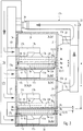
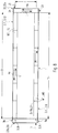
- tunnel dryer is used to dry moldings 2 of ceramic or similar material, in particular plate-shaped moldings 2, for example facade panels, tiles or roof tiles, in a pass through a tunnel 3, at one end a tunnel entrance 3a and has at its other end a tunnel exit 3b.
- a conveyor line F In the cavity 3c of the tunnel 3 extends in a passage 3g a conveyor line F, on which the moldings 2 in successively arranged positions continuously or discontinuously, for example in conveying steps, are promoted.
- An associated conveyor is designated in its entirety by 4, wherein the conveying direction is denoted by 4a.
- identical or comparable parts are provided with the same reference numerals.
- the cavity 3c of the tunnel 3 is bounded by a bottom 3d, two opposite side walls 3e and a top wall 3f.
- the conveyor 4 preferably has only a single conveying plane 4b, in which the moldings 2 in the Conveying direction 4a lying behind one another and transverse to it in one or more rows R are conveyed side by side lying, wherein the moldings 2 each have a longitudinal spacing and at several rows R also have a transverse distance from each other through which drying air can flow in a manner to be described. If the conveying plane 4b is located in the middle height range of the cavity 3c, the cavity sections 3c1, 3c2 arranged above and below the conveying plane 4b are the same or the same size. In the embodiment, the conveying plane 4b is disposed lower than the average cavity height, so that the upper cavity portion 3c1 is higher and larger than the lower cavity portion 3c2.
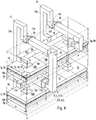
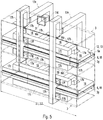
- the conveyor 4 has for positioning carrying the moldings 2 carrier 5 ( Fig. 3 ), which allow a transverse directed flow of the moldings 2 with drying air, in particular vertically from the drying air can be flowed through.
- own plate-shaped support elements 5a as perforated discs with vertical holes or horizontally arranged support grid on which the moldings 2 rest, z. B. rest with their lower broadsides.
- Such support plates 5a are preferably formed the same with a length a and a width b, wherein the width b may preferably extend over the entire inner width of the cavity 3c, taking into account small side distances c. Since the support plates 5a are vertically flowed through, they can be at their mutually facing longitudinal ends without spacing together. This makes it possible to realize large wings for the moldings 2 when using the width of the cavity 3c.
- the carrier 5 or support plates 5a are preferably arranged on conveyor carriages or trolleys 6, which can be conveyed continuously or in conveying steps through the passage 3g. If in this case the conveyor carriages or trolleys 6 abut each other in the longitudinal direction of the tunnel 3, it requires only one and simple drive z. B. a linear actuator, at the tunnel entrance 3a to move the support carriage or cart 6 through the passage 3g.
- a drive is in FIG. 1 , z. B. as a push rod, simplified and designated 7. It can be arranged in the area of a magazine or a stacking and unstacking device 8 for a Föderschlitten- or trolley stack, which is located in a longitudinal distance in front of the tunnel entrance 3a.
- a loading station 9a for loading the conveyor carriages 6 with moldings 2 can be arranged, for example offset laterally.
- a z. B. laterally offset loading station 9a makes it possible to load a positioned there conveyor carriage or trolley 6 with moldings 2, without affecting the operation of the conveyor 4.
- an unloading station 9b for unloading the moldings 2 from a arrived there carriage or wagon 6 be arranged where the moldings 2 can be unloaded and the relevant conveyor carriage or trolley 6 in the magazine or in the stack of the stacking device 8, where it is ready in the stack as storage for a next drying process.
- drying air is introduced into the tunnel 3, which sweeps the moldings 2 as a drying or air flow and thereby removes moisture.
- a drying or air flow can be directed in the tunnel 3 as a longitudinal flow L, and thereby preferably in countercurrent with respect to the conveying direction 4a of the conveyor 4, and / or as a transverse flow Q transversely to the tunnel axis.
- a plurality of air supply sub-devices 11.1 to 11.12 (FIG. 1) arranged behind one another in the tunnel longitudinal direction.
- Fig. 1 and 2 which, for example, function independently of one another and are at least partially adjustable, in particular taking into account the molding condition with respect to temperature and / or humidity and / or delivery rate.
- the tunnel 3 is divided into a plurality of longitudinal sections 3.1 to 3.12, in each of which an effective against the moldings 2 transverse air flow Q is generated by an associated feed sub-device 11.1 and so on.
- the last or last supply sub-devices in the passage direction remove the air from the surroundings of the tunnel 3, the previous supply sub-devices taking the air out of the tunnel 3.
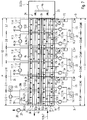
- the embodiment according to Fig. 1 and 2 differs from the embodiments according to Fig. 6 and 7 in that according to Fig. 1 and 2 the last feed divider 11.12 generates the transverse air flow Q only in the last longitudinal section 3.12, while according to FIG Fig. 6 and 7 only eleven supply sub-devices 11.1 to 11.11 are present, the last sub-device 11.11 supplies the two last longitudinal sections 3.11 and 3.12 and generates in each case the transverse air flow Q.
- all the feed subdevices 11.1 to 11.12 are according to FIG Fig. 1 and 2 and the feeding sub-apparatuses 11.1 to 11.11 according to FIG Fig. 6 and 7 the same education.
- the supply subdevices 11. 1 to 11. 10 or 11. 11 respectively generate a transverse air flow Q which is taken from the cavity 3 c of the associated tunnel section 3. 1 to 3.
- the air can be taken from the upper cavity portion 3c1 and / or lower cavity portion 3c2.
- the supply of the circulating air takes place as a transverse air flow Q at least two on both sides of the conveying plane 4b oppositely arranged air inlets 12, each of the conveying plane 4b have such a large transverse distance that the moldings 2 are movable between the air inlets 12 and from the two air inlets 12th outflowing and oppositely directed drying transverse flows Q are terrorismbar.
- each air inlet 12 has an air distributor 13 downstream of a feedline 17 of smaller cross-section in the flow direction and substantially evenly distributes the inlet airflow to a width and length equal to a longitudinal and transverse dimension a, b of an air-permeable support plate 5a corresponds. This applies both to the upper and lower air inlet 12 and to the lower and upwardly directed and transversely opposed air inlet 12.
- the relative to the conveying plane 4b opposite each other and mirror-image formed air distributor 13 each have between the associated air inlet 12 and the trajectory of the moldings 2 and the passage 3g an air distribution disc 14 with the longitudinal and transverse dimensions a, b, which has a plurality of holes 15 , which ensure a uniformity and uniform distribution of the outflowing through them drying air cross-flow Q.
- the feed ducts 17 leading to the air inlets 12 have divergent duct end portions 17a which extend conically or pyramidally divergently toward the air inlet 12.
- the air inlets 12 can be formed by a hollow, flat and in plan view preferably quadrangular distribution box 16, which has closed peripheral walls 16a and a cover wall 16b, in which the associated supply line section 17a preferably divergent flows.
- the air distribution disc 14 may be arranged, for example as a bottom wall.
- the air-permeable support plates 5a may each be formed by a perforated disc or a grid which is formed in the upper region of a support frame 18 square cross-section which forms an associated trolley 6 and with laterally arranged wheels 6a in or on guide rails 6b is moved, the the inner walls of the tunnel 3 are attached.
- each air inlets 12 or distribution boxes 16 are arranged longitudinally one behind the other in the region of each tunnel section 3.1 to 3.12, for example three, each with a feed passage section 17b extending transversely Distribution line section 17c, which extends longitudinally in the upper and lower cavity sections 3c1, 3c2, in particular on the associated side wall 3e, preferably without heat insulation, so that a heat exchange between the drying air located in the upper and lower cavity sections 3c1, 3c2 and in the distribution line section 17c located drying air can be done.
- the distribution boxes 16 may be in the longitudinal direction of transverse joints 16c together ( Fig. 4 and 5 ), this group, e.g. B.
- the distribution boxes 16 or this group can also have a longitudinal distance d from each other or from the boundary lines 3i, as it Fig. 1 shows.
- a tunnel 3 which has at least two major tunnel longitudinal sections T1, T2, which extend U-shaped or meandering next to each other and their conveying directions 4a thus extend opposite to each other, wherein they at their ends together by a conveying direction Reverse section are connected to a conveying direction reversing device 22 with each other.
- the tunnel 3 of the embodiment thus extends in a U-shape, with the main longitudinal sections T1, T2 extending parallel to one another and also the tunnel inlet 3a and the tunnel outlet 3b facing in opposite directions.
- the two longitudinal sections T1, T2 are preferably of the same length and extend along their entire length, which does not have to be, they or the tunnel entrance 3a and the tunnel exit 3b are substantially transversely side by side, z. B. with or without distance laterally or vertically next to each other.
- the opposing longitudinal sections T1, T2 are arranged one above the other.
- the arrangement is also made such that the tunnel sections 3.1 to 3.12 are arranged side by side or one above the other without clearance, resulting in a simple arrangement.
- tunnel 3 or its tunnel wall from arranged in its longitudinal direction one behind the other and preferably equal to each other or of equal length formed modules M, which are juxtaposed at their longitudinal ends and in this position by z.
- fasteners 19 shown attached or are juxtaposed and positioned or anchored due to their own weight.
- the length of the modules M corresponds to the length of the preferably equally long tunnel sections 3.1 to 3.12, so that the division joints 21 between the modules M correspond to the imaginary lines between the tunnel longitudinal sections 3.1 to 3.12 and thus the air supply sub-devices 11.1 to 11.12 each at least one associated Module M are assigned.
- the division into modules M has the advantage that not only the tunnel 3 can be made in similar longitudinal sections, prefabricated and stored, but these modules M can each z. B. with the associated feeder part device 11.1 to 11.12 and z. B. correspondingly long sections of the guide rails 6 b are prefabricated so that it requires only a Anaptetzens and positioning of the prefabricated modules M at the construction site of the tunnel dryer 1.
- the above-described modular construction can be realized for the main longitudinal section T1 or for the main longitudinal section T2 or for both main longitudinal sections T1, T2.
- the latter show the embodiments according to Fig. 1 to 7 in which the modules M extend with the dividing lines 21 across both main longitudinal sections T1, T2 and are preferably made in one piece.
- the main longitudinal sections T1, T2 each consist of modules arranged one behind the other (not shown), these submodules can be prefabricated with the respectively associated air supply subdevices 11.1 to 11.11 or 11.12.
- the modules M When the modules M extend transversely across both major longitudinal sections T1, T2, they may each be associated with both and opposite each other Tunnellticiansab 3.1 to 3.12 and air supply sub-devices 11.1 to 11.11 and 11.12 are prefabricated.
- the modular construction extending over both main longitudinal sections T1, T2 makes it possible, in particular, to have a narrow or low construction, when the main longitudinal sections T1, T2 are arranged in the transverse direction without a distance from one another and thus against each other and are preferably made in one piece.
- a tunnel wall can be saved, because the existing between the main longitudinal sections T1, T2 intermediate wall two main longitudinal sections T1, T2 serves as a wall.
- the existing intermediate wall 3h forms the top wall 3f of the lower main longitudinal section T1 and the bottom wall 3d of the upper main longitudinal section T2.
- the conveying direction reversing device 22 is formed by a transverse conveyor 22a, which is adapted to each convey the above the main longitudinal section T1 out into a first cross conveyor station 23 trolley 6 transversely, here upwards, in a second cross conveyor station 24, in which Trolley 6 is in alignment with the main longitudinal section T2 and by a longitudinally or rearwardly directed second conveyor drive 25 through the second main longitudinal section T2 is conveyed.
- the first and the second conveyor drive 7, 25 may be formed, for example by a slide, all advancing in series in front of the respective conveyor drive 7, 25 trolley 6 respectively by ajurinconstru the abutting trolleys 6 advances and then moved back to a another of the zugenörigen cross conveyor station 23 and 24 transversely interposed trolley 6, the other in the main longitudinal section T1 and T2 upstream trolley 6 advances.
- the transverse conveyor 22a is particularly advantageous to design the transverse conveyor 22a such that the transverse distance e between the passages 3g of the tunnel longitudinal sections T1, T2 is a multiple of the height h of the passages 3g or trolley 6 and the transverse conveyor 22 is adapted to each of the uppermost ones the first conveyor station 23 located trolley 6 in the second conveyor station 24 to move.
- Such a transverse conveyor 22 is thus able to move the uppermost of one or more located in the first conveyor station 23 carrier 5 or trolley 6 in the second conveyor station 24, no matter how high the stack is. In this way, a memory is created, which makes it possible to deposit between the conveyor stations 23, 24 a certain number of carrier 5 or trolley 6 and, for example, at a Store discharge at the tunnel outlet 3b, without significantly affecting the conveying and drying operation.
- the upward-acting transverse conveyor 22a may be an elevator.
- a memory comparable to the above-described memory also enables the unstacking device 8, if it is designed and functioning in accordance with the cross conveyor 22a, being adapted to stack the unloaded carriers 5 and trolleys 6 at the respective stacking height at the top of the stack Pillar can pass.
- transversely juxtaposed and / or superimposed main longitudinal sections T1, T2 Another advantage of transversely juxtaposed and / or superimposed main longitudinal sections T1, T2 is that between them heat exchange can take place and thus the heat loss is reduced and also between the main longitudinal sections T1, T2 need not be provided insulation.
- the z. B. is formed by the two last longitudinal tunnel sections 3.11 and 3.12, are formed equal to each other.
- these subdevices 11.1 to 11.10 each generate a drying transverse air flow Q in the circuit, wherein the circulating air is removed at a removal opening 31, which is located in the region of the associated longitudinal tunnel section 3.1 to 3.10 in the tunnel wall, z.
- the removal opening 31 can be arranged in the region of the lower and / or upper cavity section 3c1, 3c2.
- the removal opening 31 may be located in the region of the upper cavity portion, as is the Fig. 3 to 5 demonstrate.
- the removal opening 31 can also be located at least in the area of the main longitudinal section T1 in the lower cavity section 3c2, as it is Fig. 6 shows.
- the removal openings 31 for the air supply sub-device 11.1 to 11.6 of the first and lower main longitudinal section T1 in the lower and / or upper cavity portion 3c1, 3c2 of the second or upper main longitudinal section T2 to arrange how it Fig. 7 exemplifies.
- short supply lines 17 between the removal openings 31 and the associated air inlets 12 can be achieved, although in each case the removal opening 31 is the associated air inlet 12 in the passage direction or in the conveying direction 4a of the moldings 2 pre-offset by one or more longitudinal sections 3.1 to 3.11.
- the supply line 17 may extend from one side of the tunnel assembly to the opposite side, wherein it traverses the here formed by the superposed main longitudinal sections T1, T2 double tunnel.
- the tunnel wall 3e projecting line sections 17d provided in which an adjustable throttle 32 is located, the z. B. is formed by a pivotable throttle.
- a line bridge 17e extends over the double tunnel, which extends on the other side down to two superimposed projecting line sections 17f, 17g passing through the associated side wall 3e and connected to the respective associated distribution line 17c, which in upper and lower cavity portion 3c1, 3c2 is located. This applies to the line sections 17d, 17f, 17g in both longitudinal tunnel sections T1, T2 or above and below.
- the supply lines 17 for the lower main longitudinal section T1 and the upper main longitudinal section T2 differ in that in the former case the bypass section 17e is associated with a burner 33, and by vertical sections 17h of different lengths.
- the bridging portions 17 e is associated with an air conveyor 34, z. B. a fan with a paddle wheel.
- the outer feed line 35 branches into two feed line branches 35a, 35b, which are connected to the lateral line sections 17h, 17f, 17g and the line sections 17c, 17d, 17a with the associated air inlets 12 and distribution boxes 16, respectively.
- the transverse airflow Q produced by the last supply subdevice 11.11 and exiting to at least one associated air inlet 12 or distribution box 16 becomes not recirculated again, as is the case with the other supply subdevices 11.1 to 11.10. Therefore, the air pressure of the dividing device 11.11 generates the longitudinal air flow L, which flows through the tunnel 3 in countercurrent to the conveying direction 4a due to an air barrier 36 arranged at the tunnel end 3b.
- an exhaust duct 37 may optionally be arranged with a further air conveyor 38, which dissipates at least a portion of the longitudinal air flow L, see, for. B. Fig. 6 and 7 ,
- the feed subdevices 11.1 to 11.10 form two feed groups G1, G2 arranged one behind the other along the conveying direction 4a, which can be regulated on the one hand and regulated differently on the other hand.
- the first group G1, the z. B. is arranged in the main longitudinal section T1, z. B. extend from the tunnel entrance 3a over a part or the entire length of this main longitudinal section T1.
- the feed sub-apparatuses 11.1 to 11.6 of the first group G1 are each assigned a control device 39 which controls the drying performance of the associated feed subdevice 11.1 to 11.6 so that the blanks 2 suffer no damage due to excessive drying performance, eg. B. unintentionally deform or get cracks.
- the air flow rate and / or the air temperature and / or the moisture content of the respective transverse air flow Q can be selectively increased or decreased, depending on the humidity value of the drying air in the tunnel 3, in particular the existing in the tunnel longitudinal section 3.1 to 3.6 drying air, the is determined as actual value, z. B. by a humidity sensor 41, wherein the control device 39, taking into account a specific setpoint, the drying performance so regulated that a predetermined actual moisture value of the moldings 2 is achieved.
- the control devices 39 can be preset with increasing distance from the tunnel entrance 3a setpoints so that with decreasing distance from the tunnel entrance 3a a sinking certain actual value of the respective moldings 2 is achieved.
- the above-described increase or decrease in the flow rate and / or the temperature and / or the humidity value of the associated cross-air flow Q can be for at least one or more of the sub-devices 11.1 to 11.6 by a corresponding control of the heat output of the burner 33 and / or the amount of associated transverse air flow of the Air conveyor 34 and / or an air inlet 42 regulate, which is selectively enlarged or reduced by an associated adjusting motor 43.
- the transverse air flow Q of larger flow rate shown by the feeder part device 11.11 or 11.12 can also be regulated by a control device 39. For reasons of simplification, reference is therefore made to the above-described regulation for the subdevices 11.1 to 11.6.
- the second group G2 which is arranged downstream of the first group G1 in the passage direction, and in the embodiment arranged in the main longitudinal section T2, may also be associated with each subdevice 11.7 to 11.10 an identical or similar control device 39, the drying capacity and / or delivery rate of the associated Transverse airflow Q regulated in response to each measured in the associated tunnel section with a humidity sensor, not shown.
- a control or display device 40 which actuates a particular function or actuates a display device when the temperature exceeds or falls short of a specific value of the temperature in the associated longitudinal section 3.7 to 3.10.
- the drying process may be designed so that in at least a first longitudinal region of the tunnel 3, z. B. in the group area G1 or in the main longitudinal section T1, a first drying or predrying takes place, and in the second longitudinal region, for. B. at least in the group area G2 or in the main longitudinal section T2, a final drying takes place.
- the drying in the first longitudinal region can be more intense than in the second longitudinal region.
- the supply subdevices 11.1 to 11.3 in the first group G1 are arranged and arranged such that they can be arranged in each case by means of a line branch with a longitudinally extending line section 17k, in which one or two air conveyors 34 can be arranged, along two extend adjacent or over several tunnel longitudinal sections 3.1 to 3.6 or modules M1 to M6.
- the number of feed sub-devices can be reduced or halved, in this case to three pieces, and the effective range or outflow range of the associated transverse flow Q can be increased longitudinally or distributed longitudinally in sub-streams.
- these sub-devices for. B. 11.1 to 11.3, designed so that the air extraction of the respective associated cross-air circuit not or not only the associated tunnel longitudinal section, z. B. 3.1 and 3.2 or M1 and M2; 3.3 and 3.4 or M3 and M4; 3.5 and 3.6 or M5 and M6, but one in the passage direction adjacent or further upstream tunnel longitudinal section or module is removed. That is, the associated line section 17i extends in each case up to a tunnel longitudinal section, which is arranged directly or multiply in the conveying direction 4a of the moldings 2, in particular in each case adjacent.
- each supply sub-device 11.1 to 11.3, the air for the respective associated cross-flow Q can be removed from two removal openings 31, which are located in the first and second main longitudinal section T1, T2, in particular in the associated tunnel longitudinal section 3.1 to 3.11 or z. B. also 3.12 or module M1 to M6.
- each of the removal openings 31 extending withdrawal line sections 17 d, 17 j may each be arranged a locking device 44 which is optional to open and close, z. B. by a motor 45. In this way, the amount of the respective bleed air can either reduce or increase or lock.
- Such an axially pre-staggered arrangement of at least one removal opening 31 and / or control or regulation of the extraction air can also be present in the supply sub-apparatuses 11.1 to 11.6 of the previously described embodiments.
- Fig. 7 is the removal opening 31 for the removal of the air for the transverse air flow Q respectively in the area, in particular in the direction of the conveying direction 4a facing end, one or two adjacent tunnel longitudinal sections, z. B. 3.1 and 3.2 or modules M1 and M2, arranged, or by a feeder-part device, for. B. 11.1, are jointly combinable.
- the supply line section 17i extends counter to the conveying direction 4a.
- the line section 17i bridges the existing therebetween boundary line 3i and dividing joint 21st
- the tunnel main longitudinal section T1, T2 may be arranged in another arrangement next to each other, for. B. horizontally next to each other.
- FIG. 8 Such an embodiment shows Fig. 8 in a schematic representation, wherein the main longitudinal sections T1, T2 may have a horizontal distance f from each other (shown) or may be arranged directly next to each other (not shown).
- the reversing device 22 or the transverse conveyor 22a is adapted to convey the carriers 5 or trolleys 6 equipped with blanks 2 horizontally.
- an identical or similar reversing device 22b may be arranged with a same or similar transverse conveyor 22c for conveying the unloaded carriers 5 or trolleys 6 horizontally directly to the loading station 9a or into a standby station set back. From this position, the further promotion of the loaded or still to be loaded carrier 5 or trolley 6 in the tunnel 3 done.
- main longitudinal sections T1, T2 are arranged side by side directly to each other, they may have a common partition wall, and z. Example, be integrally connected to each other, as has already been described comparable in the above-described embodiment.
- the modules M1 to M6 can extend horizontally over both main longitudinal sections T1, T2.
Landscapes
- Engineering & Computer Science (AREA)
- Mechanical Engineering (AREA)
- General Engineering & Computer Science (AREA)
- Ceramic Engineering (AREA)
- Structural Engineering (AREA)
- Chemical & Material Sciences (AREA)
- Drying Of Solid Materials (AREA)
- Tunnel Furnaces (AREA)
- Press-Shaping Or Shaping Using Conveyers (AREA)
Claims (11)
- Tunnel de séchage (1), approprié au séchage d'ébauches (2), comprenant- une pluralité de supports (5) servant à supporter les ébauches (2) qui sont disposées les unes derrière les autres dans une cavité (3c) d'un tunnel (3) le long d'un passage de tunnel (3g), dans lequel la cavité (3c) du tunnel (3) est limitée par un fond (3d), deux parois latérales (3e) en regard l'une de l'autre et une paroi supérieure (3f) ;- un dispositif d'acheminement (11) servant à l'acheminement d'air de séchage dans le tunnel (3),- une pluralité d'entrées d'air (12) disposées longitudinalement les unes derrière les autres sous la forme de boîtes de distribution d'air (16) qui sont respectivement disposées en regard les unes des autres transversalement de part et d'autre du passage (3g) et orientées vers le passage (3g), dans lequel les entrées d'air (12) sont formées respectivement par des plaques de distribution d'air (14) dotées de trous (15) et disposées parallèlement et suivant une symétrie miroir au-dessus et en-dessous des supports (5), dans lequel les plaques de distribution d'air (14) dotées de trous (15) sont disposées dans les régions de fond des boîtes de distribution d'air (16) tournées vers les supports (5), dans lequel les entrées d'air (12) produisent respectivement, lors du fonctionnement, un circuit d'écoulement à l'aide duquel de l'air peut être prélevé au niveau d'au moins une sortie d'air (31) dans le tunnel (3) et à nouveau introduit à travers les entrées d'air (12) ;
caractérisé en ce que- le dispositif de séchage comporte en outre un dispositif de transport (4) pour transporter les supports (5) dans un sens de transport (4a) à travers le passage de tunnel (3g), les supports (5) étant formés par des éléments de support (5a) plans et perméables à l'air qui sont déplaçables à travers le passage (3g) dans le sens de transport (4a) s'étendant dans la direction longitudinale du tunnel de séchage (1),
les éléments de support (5a) étant formés respectivement par une plaque perforée ou une grille et
le dispositif de transport (4) étant conçu pour transporter les supports (5) à travers le passage (3g) dans un seul plan de transport (4b) dans le sens de transport (4a) ;- les entrées d'air (12) forment plusieurs dispositifs partiels d'acheminement d'air (11.1 à 11.11 ou 11.12) disposés les uns derrière les autres le long du passage (3g), les entrées d'air (12) étant formées respectivement par une boîte de distribution (16) creuse, plane et quadrangulaire en vue de dessus, laquelle comprend des parois périphériques (16a) fermées et une paroi supérieure (16b), la plaque de distribution d'air (14) étant disposée en tant que paroi de fond dans la région inférieure de la boîte de distribution (16) ;- la sortie d'air (31) se trouve dans une paroi latérale (3e) du tunnel (3). - Tunnel de séchage selon l'une des revendications précédentes,
caractérisé- en ce que le tunnel (3) comprend au moins deux parties longitudinales principales (T1, T2),- qui sont, au moins sur une partie de leur longueur, juxtaposées de manière à présenter des sens de transport (4a) opposés les uns aux autres,- et en ce que deux extrémités (3a, 3b), orientées dans un sens, des parties longitudinales principales (T1, T2) sont reliées l'une à l'autre par un dispositif d'inversion de sens de transport (22). - Tunnel de séchage (1) selon l'une des revendications précédentes,
caractérisé en ce que
le tunnel (3) est constitué de modules de tunnel (M) disposés les uns derrière les autres dans sa direction longitudinale. - Tunnel de séchage selon l'une des revendications précédentes,
caractérisé en ce que
les supports (5a) sont disposés respectivement sur un chariot de transport (6). - Tunnel de séchage selon la revendication 4, caractérisé en ce que
les dimensions longitudinales et transversales horizontales des éléments de support (5a) correspondent sensiblement respectivement approximativement à des mêmes dimensions longitudinales et transversales horizontales des chariots de transport (6) et s'étendent de préférence sensiblement sur toute la largeur du passage (3g). - Tunnel de séchage selon l'une des revendications précédentes 2 à 5,
caractérisé en ce que
la sortie d'air (31) ou une deuxième sortie d'air (31) est décalée dans le sens de transport (4a) par rapport à l'entrée d'air associée (12),
par exemple est disposée dans la région d'un dispositif partiel d'acheminement (11.1 à 11.8) qui est décalé d'un ou de plusieurs dispositifs partiels d'acheminement dans le sens de transport (4a),
ou est par exemple disposée dans la région d'un module (M1 à M6) qui est décalé d'un ou de plusieurs modules dans le sens de transport (4a). - Tunnel de séchage selon l'une des revendications 3 à 6,
caractérisé en ce que
la sortie d'air (31) ou la deuxième sortie d'air (31) est disposée par rapport à l'entrée d'air associée (12) dans la deuxième partie longitudinale principale de tunnel (T2), en particulier est disposée en regard transversalement dans celle-ci. - Tunnel de séchage selon l'une des revendications précédentes,
caractérisé en ce
qu'un dispositif partiel d'acheminement (11.11 ; 11.12) servant à acheminer de l'air depuis l'extérieur du tunnel (3) est disposé dans la région d'extrémité du tunnel (3), ce dispositif partiel d'acheminement (11.11 ; 11.12) acheminant l'air de préférence jusqu'à la ou les entrées d'air (12) disposées dans cette région d'extrémité. - Tunnel de séchage selon la revendication 8,
caractérisé en ce que
le dispositif de séchage est réalisé de telle sorte que la quantité d'air qui est acheminée jusqu'au dispositif partiel (11.11 ; 11.12) disposé dans la région d'extrémité du tunnel (3) est supérieure à la quantité de flux d'air transversal transportée respectivement par les dispositifs partiels d'acheminement restants (11.1 à 11.10). - Tunnel de séchage selon l'une des revendications 2 à 9,
caractérisé en ce
qu'un dispositif de régulation (39) est respectivement associé aux dispositifs partiels d'acheminement (11.1 à 11.6) pour réguler la température et/ou la quantité d'air du flux d'air transversal (Q) en fonction de la teneur en humidité des ébauches (2) ou de l'humidité de l'air présente dans la partie longitudinale de tunnel (3.1 à 3.6) respective. - Tunnel de séchage selon l'une des revendications 4 à 10,
caractérisé en ce que
les parties longitudinales principales (T1, T2) sont juxtaposées sans espacement, de préférence sont reliées les unes aux autres d'un seul tenant, en particulier sont réalisées de manière à présenter une paroi intermédiaire commune (3h).
Applications Claiming Priority (1)
| Application Number | Priority Date | Filing Date | Title |
|---|---|---|---|
| DE102008013012A DE102008013012B4 (de) | 2008-03-07 | 2008-03-07 | Tunneltrockner zum Trocknen von Formlingen, mit in Querabständen einander gegenüberliegend angeordneten Lufteinlässen |
Publications (3)
| Publication Number | Publication Date |
|---|---|
| EP2098811A2 EP2098811A2 (fr) | 2009-09-09 |
| EP2098811A3 EP2098811A3 (fr) | 2014-08-27 |
| EP2098811B1 true EP2098811B1 (fr) | 2019-06-12 |
Family
ID=40733188
Family Applications (1)
| Application Number | Title | Priority Date | Filing Date |
|---|---|---|---|
| EP09154501.2A Active EP2098811B1 (fr) | 2008-03-07 | 2009-03-06 | Tunnel de séchage pour sécher des ébauches, doté d'ouvertures d'air agencées de manière opposée et avec un écart transversal, et module de tunnel pour un tunnel de séchage |
Country Status (4)
| Country | Link |
|---|---|
| EP (1) | EP2098811B1 (fr) |
| CN (1) | CN101526305A (fr) |
| DE (1) | DE102008013012B4 (fr) |
| ES (1) | ES2744381T3 (fr) |
Families Citing this family (17)
| Publication number | Priority date | Publication date | Assignee | Title |
|---|---|---|---|---|
| ITPR20090099A1 (it) * | 2009-11-27 | 2011-05-28 | Imas Srl | Processo di essiccazione di prodotti pressati o estrusi con formati speciali e suo apparato |
| CN101806533B (zh) * | 2010-03-17 | 2013-01-23 | 云南昆船设计研究院 | 双侧交替进风隧道式气流加热干燥或冷却装置 |
| DE102010054493B4 (de) * | 2010-12-14 | 2017-06-01 | Hildebrand Holztechnik Gmbh | Trocknungsvorrichtung |
| DE202011051701U1 (de) * | 2011-10-20 | 2013-01-23 | Hans Lingl Anlagenbau Und Verfahrenstechnik Gmbh & Co. Kg | Trockeneinrichtung |
| CN104048490A (zh) * | 2014-05-04 | 2014-09-17 | 赵宽学 | 陶土瓦坯支撑干燥装置 |
| FR3027659A1 (fr) * | 2014-10-23 | 2016-04-29 | Ceritherm | Tunnel de sechage pour produits ceramiques |
| DE102015209370B3 (de) * | 2015-05-21 | 2016-09-08 | Lavatec Laundry Technology Gmbh | Trockner |
| CN106918205B (zh) * | 2017-03-22 | 2022-11-01 | 中船双瑞(洛阳)特种装备股份有限公司 | 一种减少大型铸件侵入性气孔缺陷的方法以及烘干炉 |
| ES2684054B1 (es) * | 2017-03-28 | 2019-07-29 | Corporacion Omegazeta S L | Horno para el fraguado de paneles de mortero de cemento e instalación correspondiente |
| IT201900025543A1 (it) * | 2019-12-24 | 2021-06-24 | Scg Building Mat Co Ltd | Stazione di essiccazione per lastre ceramiche |
| EP4107456B1 (fr) * | 2020-02-18 | 2024-07-17 | System Ceramics S.p.A. | Sécheur pour carreaux ou dalles de céramique |
| CA3252470A1 (fr) | 2022-05-03 | 2025-07-08 | Reinhard Brunner | Dispositif de séchage en continu |
| DE102022120887B4 (de) | 2022-05-03 | 2025-01-02 | Reinhard Brunner | Kanal-Trocknungsvorrichtung |
| EP4276398A1 (fr) | 2022-05-09 | 2023-11-15 | Reinhard Brunner | Dispositif de séchage de canal |
| DE102022130433B4 (de) | 2022-05-09 | 2024-09-05 | Reinhard Brunner | Kanal-Trocknungsvorrichtung |
| CN115751908A (zh) * | 2022-10-19 | 2023-03-07 | 故城北新建材有限公司 | 一种板材干燥布风自动调节系统 |
| CN118219402B (zh) * | 2023-12-26 | 2024-08-23 | 广东顺优建设有限公司 | 一种建筑水泥预制件的定型速干设备 |
Citations (6)
| Publication number | Priority date | Publication date | Assignee | Title |
|---|---|---|---|---|
| US2197776A (en) * | 1938-09-03 | 1940-04-23 | Wesley H Argabrite | Apparatus for drying leather |
| GB656695A (en) * | 1947-11-17 | 1951-08-29 | William Avery Clements | Improvements in and relating to the drying of ceramic objects |
| DE2033355A1 (en) * | 1970-03-10 | 1971-09-23 | Öspag Österreichische Sanitär-Keramik- und Porzellan-Industrie AG, Wien | Sanitary ceramic ware drying oven |
| FR2413342A1 (fr) * | 1977-12-30 | 1979-07-27 | Fuchs & Co Ag | Installation pour fabriquer des articles moules cuits en brique |
| EP0343618A2 (fr) * | 1988-05-27 | 1989-11-29 | Erlus Baustoffwerke AG | Procédé et dispositif pour sécher des ébauches à bloc creux |
| EP0499768A1 (fr) * | 1991-02-18 | 1992-08-26 | POPPI S.p.A. | Dispositif de séchage rapide, en particulier pour carreaux en céramique vertes |
Family Cites Families (4)
| Publication number | Priority date | Publication date | Assignee | Title |
|---|---|---|---|---|
| DE3210652A1 (de) * | 1982-03-23 | 1983-10-06 | Fuchs & Co Ag | Verfahren und vorrichtung zur belueftung von trockengut in einem tunneltrockner |
| IT1185911B (it) * | 1985-09-13 | 1987-11-18 | Art Ceramiche Srl | Procedimento per l'essiccazione rapida di ceramica e impianto per realizzarlo |
| DE3708642C2 (de) * | 1987-03-17 | 1997-08-14 | Imas S P A | Vorrichtung für die rasche Trocknung von keramischen Rohprodukten, insbesondere von Fliesen |
| DE4002643A1 (de) * | 1990-01-30 | 1991-08-08 | Meindl Josef Ohg | Vorrichtung zum trocknen keramischer produkte, insbesondere ziegel |
-
2008
- 2008-03-07 DE DE102008013012A patent/DE102008013012B4/de not_active Expired - Fee Related
-
2009
- 2009-03-06 EP EP09154501.2A patent/EP2098811B1/fr active Active
- 2009-03-06 ES ES09154501T patent/ES2744381T3/es active Active
- 2009-03-09 CN CN200910127215A patent/CN101526305A/zh active Pending
Patent Citations (6)
| Publication number | Priority date | Publication date | Assignee | Title |
|---|---|---|---|---|
| US2197776A (en) * | 1938-09-03 | 1940-04-23 | Wesley H Argabrite | Apparatus for drying leather |
| GB656695A (en) * | 1947-11-17 | 1951-08-29 | William Avery Clements | Improvements in and relating to the drying of ceramic objects |
| DE2033355A1 (en) * | 1970-03-10 | 1971-09-23 | Öspag Österreichische Sanitär-Keramik- und Porzellan-Industrie AG, Wien | Sanitary ceramic ware drying oven |
| FR2413342A1 (fr) * | 1977-12-30 | 1979-07-27 | Fuchs & Co Ag | Installation pour fabriquer des articles moules cuits en brique |
| EP0343618A2 (fr) * | 1988-05-27 | 1989-11-29 | Erlus Baustoffwerke AG | Procédé et dispositif pour sécher des ébauches à bloc creux |
| EP0499768A1 (fr) * | 1991-02-18 | 1992-08-26 | POPPI S.p.A. | Dispositif de séchage rapide, en particulier pour carreaux en céramique vertes |
Also Published As
| Publication number | Publication date |
|---|---|
| EP2098811A2 (fr) | 2009-09-09 |
| DE102008013012B4 (de) | 2010-08-12 |
| ES2744381T3 (es) | 2020-02-24 |
| EP2098811A3 (fr) | 2014-08-27 |
| DE102008013012A1 (de) | 2009-09-10 |
| CN101526305A (zh) | 2009-09-09 |
Similar Documents
| Publication | Publication Date | Title |
|---|---|---|
| DE102008013012B4 (de) | Tunneltrockner zum Trocknen von Formlingen, mit in Querabständen einander gegenüberliegend angeordneten Lufteinlässen | |
| EP0712481B1 (fr) | Procede et dispositif de sechage de panneaux | |
| DE10146179C1 (de) | Anlage zum Trocknen von Gipskartonplatten | |
| DE102016125060B4 (de) | Vorrichtung zum Temperieren von Gegenständen | |
| DE69801431T2 (de) | Verfahren und vorrichtung zum behandeln von plattenförmigem gut, insbesondere von leiterplatten | |
| DE102020201705A1 (de) | Temperieranlage | |
| EP2946158B1 (fr) | Dispositif de régulation de la température d'objets | |
| EP0707530B1 (fr) | Procede et installation pour le sechage et/ou la cuisson de briques vertes | |
| EP0089408B1 (fr) | Procédé et dispositif pour la ventilation de la matière à sécher dans un tunnel de séchage | |
| EP0840876B1 (fr) | Procede et dispositif de sechage de briques crues ceramique | |
| EP4107457A1 (fr) | Installation de mise en température | |
| DE20016911U1 (de) | Vorrichtung zum Trocknen von Gegenständen | |
| DE102018113685A1 (de) | Anlage zum Trocknen von Fahrzeugkarosserien | |
| DE69221740T2 (de) | Verfahren zum Trocknen von perforierten Ziegelsteinen und Vorrichtung zum Durchführen des Verfahrens. | |
| WO2025036527A1 (fr) | Système de régulation de température permettant de réguler la température de pièces, et procédé de régulation de la température de pièces | |
| WO2025036528A1 (fr) | Système de régulation de température permettant de réguler la température de pièces, et procédé de régulation de la température de pièces | |
| DE19719183C1 (de) | Vorrichtung zum Trocknen und Verfahren zum Trocknen von Keramikformlingen | |
| WO2005003661A1 (fr) | Four a circulation d'air | |
| DE102020004454A1 (de) | Trockner zum Trocknen eines plattenförmigen Guts | |
| EP0877220A2 (fr) | Dispositif et procédé de séchage de corps céramiques moulés | |
| DE2405870B2 (de) | Trockner fuer keramische formlinge | |
| EP2181298B1 (fr) | Procédé, four de séchage d'une bande de matériau avec de l'air chaud et utilisation du dispositif | |
| EP2138301A1 (fr) | Installation à double bande avec chauffage | |
| EP0177917B1 (fr) | Four tunnel à deux canaux parallèles | |
| DE2043880A1 (de) | Verfahren zur Wärmebehandlung von auf der Oberflache mit z B Farbe, Lack od dgl behandelten Gegenstanden, insbesondere aus Holz, und Vorrichtung zur Durchfuhrung des Verfahrens |
Legal Events
| Date | Code | Title | Description |
|---|---|---|---|
| PUAI | Public reference made under article 153(3) epc to a published international application that has entered the european phase |
Free format text: ORIGINAL CODE: 0009012 |
|
| AK | Designated contracting states |
Kind code of ref document: A2 Designated state(s): AT BE BG CH CY CZ DE DK EE ES FI FR GB GR HR HU IE IS IT LI LT LU LV MC MK MT NL NO PL PT RO SE SI SK TR |
|
| AX | Request for extension of the european patent |
Extension state: AL BA RS |
|
| RIC1 | Information provided on ipc code assigned before grant |
Ipc: F26B 15/10 20060101AFI20140326BHEP Ipc: F26B 15/14 20060101ALI20140326BHEP Ipc: B28B 11/24 20060101ALI20140326BHEP Ipc: F26B 21/04 20060101ALI20140326BHEP |
|
| PUAL | Search report despatched |
Free format text: ORIGINAL CODE: 0009013 |
|
| AK | Designated contracting states |
Kind code of ref document: A3 Designated state(s): AT BE BG CH CY CZ DE DK EE ES FI FR GB GR HR HU IE IS IT LI LT LU LV MC MK MT NL NO PL PT RO SE SI SK TR |
|
| AX | Request for extension of the european patent |
Extension state: AL BA RS |
|
| RIC1 | Information provided on ipc code assigned before grant |
Ipc: B28B 11/24 20060101ALI20140724BHEP Ipc: F26B 21/04 20060101ALI20140724BHEP Ipc: F26B 15/14 20060101ALI20140724BHEP Ipc: F26B 15/10 20060101AFI20140724BHEP |
|
| 17P | Request for examination filed |
Effective date: 20150225 |
|
| RBV | Designated contracting states (corrected) |
Designated state(s): AT BE BG CH CY CZ DE DK EE ES FI FR GB GR HR HU IE IS IT LI LT LU LV MC MK MT NL NO PL PT RO SE SI SK TR |
|
| AKX | Designation fees paid |
Designated state(s): BE DE ES FR GR IT |
|
| AXX | Extension fees paid |
Extension state: RS Extension state: BA Extension state: AL |
|
| 17Q | First examination report despatched |
Effective date: 20150806 |
|
| GRAP | Despatch of communication of intention to grant a patent |
Free format text: ORIGINAL CODE: EPIDOSNIGR1 |
|
| INTG | Intention to grant announced |
Effective date: 20190107 |
|
| GRAS | Grant fee paid |
Free format text: ORIGINAL CODE: EPIDOSNIGR3 |
|
| GRAA | (expected) grant |
Free format text: ORIGINAL CODE: 0009210 |
|
| AK | Designated contracting states |
Kind code of ref document: B1 Designated state(s): BE DE ES FR GR IT |
|
| REG | Reference to a national code |
Ref country code: DE Ref legal event code: R096 Ref document number: 502009015817 Country of ref document: DE |
|
| REG | Reference to a national code |
Ref country code: GR Ref legal event code: EP Ref document number: 20190402739 Country of ref document: GR Effective date: 20191128 |
|
| REG | Reference to a national code |
Ref country code: ES Ref legal event code: FG2A Ref document number: 2744381 Country of ref document: ES Kind code of ref document: T3 Effective date: 20200224 |
|
| REG | Reference to a national code |
Ref country code: DE Ref legal event code: R097 Ref document number: 502009015817 Country of ref document: DE |
|
| PLBE | No opposition filed within time limit |
Free format text: ORIGINAL CODE: 0009261 |
|
| STAA | Information on the status of an ep patent application or granted ep patent |
Free format text: STATUS: NO OPPOSITION FILED WITHIN TIME LIMIT |
|
| PGFP | Annual fee paid to national office [announced via postgrant information from national office to epo] |
Ref country code: GR Payment date: 20200320 Year of fee payment: 12 |
|
| 26N | No opposition filed |
Effective date: 20200313 |
|
| PG25 | Lapsed in a contracting state [announced via postgrant information from national office to epo] |
Ref country code: GR Free format text: LAPSE BECAUSE OF NON-PAYMENT OF DUE FEES Effective date: 20211008 |
|
| PGFP | Annual fee paid to national office [announced via postgrant information from national office to epo] |
Ref country code: ES Payment date: 20250416 Year of fee payment: 17 |
|
| PGFP | Annual fee paid to national office [announced via postgrant information from national office to epo] |
Ref country code: IT Payment date: 20250331 Year of fee payment: 17 |
|
| PGFP | Annual fee paid to national office [announced via postgrant information from national office to epo] |
Ref country code: DE Payment date: 20260223 Year of fee payment: 18 |
|
| PGFP | Annual fee paid to national office [announced via postgrant information from national office to epo] |
Ref country code: BE Payment date: 20260323 Year of fee payment: 18 |
|
| PGFP | Annual fee paid to national office [announced via postgrant information from national office to epo] |
Ref country code: FR Payment date: 20260324 Year of fee payment: 18 |