EP2099095B1 - Utilisation d'un dispositif de représentation bidimensionnelle de scènes à l'aide d'un balayage à micro-ondes - Google Patents
Utilisation d'un dispositif de représentation bidimensionnelle de scènes à l'aide d'un balayage à micro-ondes Download PDFInfo
- Publication number
- EP2099095B1 EP2099095B1 EP09002939.8A EP09002939A EP2099095B1 EP 2099095 B1 EP2099095 B1 EP 2099095B1 EP 09002939 A EP09002939 A EP 09002939A EP 2099095 B1 EP2099095 B1 EP 2099095B1
- Authority
- EP
- European Patent Office
- Prior art keywords
- directional antenna
- subreflector
- scene
- antenna array
- image
- Prior art date
- Legal status (The legal status is an assumption and is not a legal conclusion. Google has not performed a legal analysis and makes no representation as to the accuracy of the status listed.)
- Not-in-force
Links
Images


Classifications
-
- H—ELECTRICITY
- H01—ELECTRIC ELEMENTS
- H01Q—ANTENNAS, i.e. RADIO AERIALS
- H01Q3/00—Arrangements for changing or varying the orientation or the shape of the directional pattern of the waves radiated from an antenna or antenna system
- H01Q3/02—Arrangements for changing or varying the orientation or the shape of the directional pattern of the waves radiated from an antenna or antenna system using mechanical movement of antenna or antenna system as a whole
- H01Q3/08—Arrangements for changing or varying the orientation or the shape of the directional pattern of the waves radiated from an antenna or antenna system using mechanical movement of antenna or antenna system as a whole for varying two co-ordinates of the orientation
- H01Q3/10—Arrangements for changing or varying the orientation or the shape of the directional pattern of the waves radiated from an antenna or antenna system using mechanical movement of antenna or antenna system as a whole for varying two co-ordinates of the orientation to produce a conical or spiral scan
-
- G—PHYSICS
- G01—MEASURING; TESTING
- G01S—RADIO DIRECTION-FINDING; RADIO NAVIGATION; DETERMINING DISTANCE OR VELOCITY BY USE OF RADIO WAVES; LOCATING OR PRESENCE-DETECTING BY USE OF THE REFLECTION OR RERADIATION OF RADIO WAVES; ANALOGOUS ARRANGEMENTS USING OTHER WAVES
- G01S13/00—Systems using the reflection or reradiation of radio waves, e.g. radar systems; Analogous systems using reflection or reradiation of waves whose nature or wavelength is irrelevant or unspecified
- G01S13/02—Systems using reflection of radio waves, e.g. primary radar systems; Analogous systems
- G01S13/06—Systems determining position data of a target
- G01S13/42—Simultaneous measurement of distance and other co-ordinates
- G01S13/426—Scanning radar, e.g. 3D radar
-
- G—PHYSICS
- G01—MEASURING; TESTING
- G01S—RADIO DIRECTION-FINDING; RADIO NAVIGATION; DETERMINING DISTANCE OR VELOCITY BY USE OF RADIO WAVES; LOCATING OR PRESENCE-DETECTING BY USE OF THE REFLECTION OR RERADIATION OF RADIO WAVES; ANALOGOUS ARRANGEMENTS USING OTHER WAVES
- G01S13/00—Systems using the reflection or reradiation of radio waves, e.g. radar systems; Analogous systems using reflection or reradiation of waves whose nature or wavelength is irrelevant or unspecified
- G01S13/88—Radar or analogous systems specially adapted for specific applications
- G01S13/89—Radar or analogous systems specially adapted for specific applications for mapping or imaging
-
- H—ELECTRICITY
- H01—ELECTRIC ELEMENTS
- H01Q—ANTENNAS, i.e. RADIO AERIALS
- H01Q3/00—Arrangements for changing or varying the orientation or the shape of the directional pattern of the waves radiated from an antenna or antenna system
- H01Q3/12—Arrangements for changing or varying the orientation or the shape of the directional pattern of the waves radiated from an antenna or antenna system using mechanical relative movement between primary active elements and secondary devices of antennas or antenna systems
- H01Q3/16—Arrangements for changing or varying the orientation or the shape of the directional pattern of the waves radiated from an antenna or antenna system using mechanical relative movement between primary active elements and secondary devices of antennas or antenna systems for varying relative position of primary active element and a reflecting device
-
- H—ELECTRICITY
- H01—ELECTRIC ELEMENTS
- H01Q—ANTENNAS, i.e. RADIO AERIALS
- H01Q3/00—Arrangements for changing or varying the orientation or the shape of the directional pattern of the waves radiated from an antenna or antenna system
- H01Q3/12—Arrangements for changing or varying the orientation or the shape of the directional pattern of the waves radiated from an antenna or antenna system using mechanical relative movement between primary active elements and secondary devices of antennas or antenna systems
- H01Q3/16—Arrangements for changing or varying the orientation or the shape of the directional pattern of the waves radiated from an antenna or antenna system using mechanical relative movement between primary active elements and secondary devices of antennas or antenna systems for varying relative position of primary active element and a reflecting device
- H01Q3/20—Arrangements for changing or varying the orientation or the shape of the directional pattern of the waves radiated from an antenna or antenna system using mechanical relative movement between primary active elements and secondary devices of antennas or antenna systems for varying relative position of primary active element and a reflecting device wherein the primary active element is fixed and the reflecting device is movable
Definitions
- the invention relates to the use of a device for two-dimensional imaging of scenes, e.g. of terrain, objects or persons, by continuous microwave scanning by means of a fully mechanical, movable, designed as a two-reflector antenna reflector directional antenna assembly, which consists of a rotationally symmetric main reflector, a primary radiator assembly consisting of one or more primary radiators and in the optical axis the symmetrical axis of the main reflector coincides with the directional antenna assembly, and a relatively small dimensioned relative to the main reflector, rotationally symmetric subreflector whose symmetry axis is inclined with respect to the optical axis of the directional antenna assembly, wherein first drive means for applying a rotation of the relative to the optical axis of the directional antenna assembly inclined subreflector at its apex about the optical axis of the directional antenna assembly and second drive means for exerting a movement of the entire directional antenna assembly in an at least approximate t are provided perpendicular to the direction of the optical axis
- Microwave-range passive imaging systems (1 - 300 GHz), so-called MW radiometers, are highly sensitive and frequency-selective power meters that can be used to record the natural thermal radiation behavior of matter with a physical temperature greater than 0 ° Kelvin. The thermal radiation is expressed in brightness temperatures.
- a spatially high-resolution antenna or antenna structure is used to measure the brightness temperature distribution, then this distribution can be determined as a function of location and thus also captured graphically.
- the size of the antenna or antenna structure determines the spatial resolution, which is essentially characterized by the width of the main maximum of the antenna pattern.
- the antenna diagram can now in principle be pivoted mechanically or electronically over the scene to be observed.
- the image acquisition time for a corresponding image quality is determined by the scene size to be imaged, the spatial resolution, the possible dwell time for a single resolution cell, and the sensitivity of the radiometer receiver. If several receivers can be used simultaneously, a corresponding reduction of the recording time is possible.
- an active imaging system i. a radar, wherein in each position of the antenna diagram, a signal is sent and received again.
- a signal is sent and received again.
- the devices developed to date in this regard use for the two-dimensional imaging of scenes either fully mechanical or fully electronic pivoting methods or mixed forms of these two pivoting methods. Usually, one has to work for a sufficient spatial resolution in the millimeter-wave range (for example> 30 GHz).
- WO 2007/028472 A1 For example, a method and a device for imaging test objects by means of electromagnetic waves, in particular for controlling persons for suspicious objects, are known.
- the test object is "illuminated" with electromagnetic waves.
- the waves backscattered by the test object are received and evaluated for a pictorial representation of the test object according to the synthetic aperture (SAR) principle.
- the synthetic aperture is generated by the fact that the waves emitted by a primary radiator of a two-reflector antenna are first be bundled by means of a subreflector, wherein the point of highest concentration, so the focus spot is moved on a rotationally symmetric, conical main reflector along a circle.
- the circular movement is generated by the inclined rotating sub-reflector.
- the point of highest concentration that is the focusing spot on the cone-shaped main reflector has such a small extent that it can be regarded as a virtual antenna that generates a beam with a large diverging opening angle in the far field.
- This large diverging aperture angle provides the required resolution with the help of SAR algorithms to be processed.
- the antenna beam with the large aperture angle scans the test object in a circle.
- the entire radar antenna system is additionally moved linearly, so that the test object is scanned two-dimensionally over its entire extent.
- a two-dimensional SAR method which can be realized by the use of a movable virtual antenna.
- the prerequisite is therefore always an active imaging system with microwave transmitter and receiver according to the SAR radar principle.
- the invention is based on the object to provide a use of a device with a two-reflector directional antenna array, with the help of active or passive microwave scanning large fields of view and thus scenes in a short time and with acceptable image quality without the required in a SAR evaluation high processing and coherence effort when using less possible, simply constructed components can be mapped so that costs, effort and weight can be kept as low as possible.
- the invention proposes a special use of a device for two-dimensional imaging of scenes according to claim 1.
- Main reflector shape, Subreflektorform, primary radiator, distance primary radiator sub-reflector and distance Subreflector main reflector as focusing parameters are inventively coordinated so that adjusts an optimal focus and field size for a certain scene distance. Furthermore, the focusing parameters and the movement speeds of the two drive means according to the invention are set so that a continuous continuous scanning of the scene results from a focus spot moving in the respective scene distance in a trajectory consisting of a resulting from the rotation of the subreflector trajectory and a is combined by the movement of the directional antenna array transverse to its optical axis resulting trajectory and which at least approximately has the shape of a tangled cycloid.
- the present invention proposes a fully mechanical two-dimensional imaging system using a combination of main reflector, rotationally-moved subreflector inclined to the optical axis, and feed antenna as electromagnetic-wave focusing optics.
- the combination of these three assemblies will be referred to as overall assembly below.
- a fixed and symmetrically aligned, so unsatisfied sub-reflector such an arrangement is also referred to as Cassegrain antenna or Gregory antenna.
- Two-reflector directional antenna arrangements with a rotating subreflector, which is inclined with respect to the optical antenna axis, are for example out EP 0 514 886 A1 and EP 0 002 982 A1 known.
- the small subreflector which is small relative to the main reflector, is advantageously used e.g. moved by a fast-rotating micromotor, whereby the illumination area on the main reflector using the rotational symmetry locally changed, i. e. e.g. is also rotated.
- the antenna diagram of the overall arrangement also describes a trajectory (locus) in space, e.g. may be a circle or an ellipse at the scene distance from the imaging system.
- the second image dimension can be obtained with a suitable amplitude of the deflection.
- the overall arrangement can also be moved in two dimensions, e.g. To extend the scene size, which also movement must be much slower than the sub-reflector rotation.
- the inventive combination of very fast movement of a small mass, namely the subreflector, and relatively slow movement of a considerably larger mass, namely the overall arrangement allows despite full mechanical movement a high frame rate (eg ⁇ 1 Hz) at high spatial resolution (eg ⁇ 0, 5 °) and sensitivity (eg ⁇ 1 K).
- a high frame rate eg ⁇ 1 Hz
- high spatial resolution eg ⁇ 0, 5 °
- sensitivity eg ⁇ 1 K
- the present invention draws on the use of a fast-rotating micromotor to generate the rotational motion of a likewise small subreflector of suitable but arbitrary shape in conjunction with a second, much slower movement of the entire directional antenna array, consisting of a suitable primary radiator group, rotating sub-reflector and suitable, but arbitrarily shaped, significantly larger main reflector, for fast two-dimensional imaging by means of electromagnetic waves with a minimum of receivers.
- the micro-motor forming the first drive means does not cause its own shading of the beam path, since it largely due to its small size is arranged completely in the already existing shadow area of the subreflector.
- main reflector shape, subreflector shape, food antenna, distance dining antenna sub-reflector and distance Subreflector main reflector can be set for a certain scene distance optimal focusing of the imaging unit. This can be in the near field as well as in the far field of the overall arrangement. Focusing means that in a small volume element at the scene distance the entire beam has the highest density (focusing spot) and that the electrical path lengths of the beams from the feed antenna to the volume element are almost identical. Further, by the aforementioned combination procedure, the visual field size can be simultaneously adjusted and optimized. The versatile combinability allows a high degree of adaptability of the device concept created by the invention to many requirements.
- the movement of the overall arrangement effected by the second drive means can be effected either by an eccentrically generated rocking motion, ie an angle change of the optical axis, or by a linear translatory movement in one of the optical axis vertical direction. This is especially suitable for distortion-free images in the near field.
- the movement of the overall arrangement in two dimensions is easily possible.
- each individual antenna diagram of the overall arrangement describes its own trajectory over the scene, but all overlap in a common area.
- the signal-to-noise ratio (sensitivity) of the imaging system can then be further improved by averaging, for example, according to the number of receivers or subsystem numbers.
- the overall design geometrical design must accommodate the use of multiple primary emitters to optimize focusing and field of view size for all subsystems together to scene spacing. It is also conceivable that the individual recipients capture only partial images of the scene, resulting in an overall picture which can, for example, reduce the image acquisition time.
- the obtained image data can be easily read e.g. be recorded with a data acquisition card (A / D converter) and a measuring computer in synchronism with the position, stored and on-line or off-line combined into an image and displayed or further processed. It is hereby a minimum of remaining image errors achievable, since each receiver produces a complete picture on its own and thus can be done to improve the sensitivity of a simple location-correct averaging of all images.
- a / D converter data acquisition card
- the irregular sampling and unequal sample density generated in the scene by the image capturing principle can be localized (weighted or unweighted) on a regular grid in units of the spatial resolution cell, as well as for image reconstruction or generation. As a result, at least in part, the radiometric resolution in the image can be improved.
- a two-frequency or multi-frequency feed horn as a primary radiator in the primary radiator arrangement also allows simultaneous operation at two or more significantly different operating frequencies. This allows the simultaneous and geometrically similar detection of physically different effects that can significantly increase the information content, and there easily, where the laws of geometric optics nor the radiation balance dominate. In other situations, validity should be checked on an individual basis. In any case, no complicated or strong frequency dependence and no dispersion is to be expected, since practically only works with reflections on metallic structures.
- the imaging method can be used for both passive (radiometry) and active remote sensing (radar technology).
- only the corresponding device radio receiver or radar transceiver unit
- the signal propagation time is to be selected in the radar so that the echo is still received within the dwell time of the focus spot at a scene point.
- a use proposed by the invention may e.g. can be used as a monitor to protect critical infrastructures (e.g., 24/7 all-weather outdoor surveillance) because of the requirement for very high spatial resolution at a moderate frame rate.
- critical infrastructures e.g., 24/7 all-weather outdoor surveillance
- use as a detection system for optically hidden objects on portals or accesses is possible, e.g. for person control.
- Fig.1 In one embodiment, there is shown a directional antenna arrangement as may be used for a fully mechanical scanning apparatus for two-dimensional imaging of a scene according to the present invention.
- directional antenna assembly which is used as focusing optics for electromagnetic microwaves, has a combination of a main reflector 1, a rotary subreflector 2 and a primary radiator 3.
- the main reflector 1 is substantially rotationally symmetrical, as well as held by means of three supports 4, 5 and 6 on the main reflector 1 sub-reflector 2.
- the primary radiator 3 is located in coinciding with the axis of symmetry of the main reflector 1 optical axis 7 of the overall arrangement.
- the subreflector 2 is sized small relative to the main reflector 1.
- the symmetry axis of the subreflector 2 is inclined with respect to the optical axis 7 of the directional antenna array.
- a fast-rotating micromotor 8 is provided in the shadow region of the subreflector 2, so that no Strahlabschattung is generated in the beam path.
- Fig.2 shows in a frontal view of the overall arrangement is shown by the rotational movement of the subreflector 2 of the crosshatched illumination area 9 on the main reflector 1 by utilizing the rotational symmetry locally changed, ie also rotated.
- trajectory 10 locus of the central beam along which the footprint 9 moves.
- 11 effective for the illustrated momentary illumination area 9 instantaneous impingement of the central beam is designated.
- the illumination area 9 does not have to be a circle and that the point of impact 11 of the central beam does not have to lie centrally in the illumination area 9.
- the antenna diagram of the overall arrangement also describes a trajectory (locus curve) 20 in space, which may be, for example, a circle or an ellipse.
- a trajectory locus curve
- This fact is also in Figure 3 shown on the top left.
- Figure 3 top left the only generated by the subreflector trajectory 20 of a focus spot 12 at the scene distance R.
- Der aus Fig.1 apparent distance R is the distance of the scene to be imaged 13 to the imaging system.
- the scene is thereby defined in a scene level, ie in the plane in which virtually all imaged scene details are located and for which the optimal focus, ie the smallest focus spot area, is set.
- Fig.1 The total directional antenna arrangement shown is offset by an eccentric drive in an oscillating deflection movement in a direction vertical to the optical axis 7 direction.
- a second image dimension is obtained, as in FIG Figure 3 is shown lower left.
- Fig.1 is the entire directional antenna assembly with main reflector 1, Subreflektor 2 and primary radiator 3 about a horizontal pivot axis 14 which is rotatably supported at two spatially rigid fixed points 15 and 16, oscillated, so tilted.
- the eccentric drive via a with its one end up on the main reflector 1 hinged rod 17, which is hinged at its other end to a driven by a small electric motor disc 18 eccentrically.
- the disk rotatably mounted on a spatially rigid fixing point 19 rotates at an angular frequency ⁇ H.
- T H 2 ⁇ H.
- Both the small electric motor for driving the eccentric disc 18 and the micromotor 8 for generating the rotational movement of the subreflector 2 do not cause their own shading in the beam path.
- the micromotor 8 is mounted as far as possible completely in the already existing shadow area of the subreflector 2.
- the drive for the subreflector rotation and the drive for the movement of the overall arrangement to one another are designed such that the movement speed of the subreflector is very high relative to the movement speed of the entire directional antenna arrangement.
- the beam generated by the primary radiator 3 is thus in the in Fig.1
- the overall arrangement shown is deflected over the subreflector 2 rotating rapidly with an angular frequency ⁇ S onto the main reflector 1 and from there at a distance R onto the scene to be imaged 13. Together with the rocking motion of the overall arrangement generated by the eccentric drive driven by the angular frequency ⁇ H , a two-dimensional one is produced Scanning the scene reached. This situation applies to both transmitting and receiving operation.
- the movement of the overall arrangement can be realized by a linear translational motion instead of the rocking motion described above.
- the overall arrangement can in principle also be moved in two dimensions transversely to the optical axis 7.
- the shape of the main reflector 1, the shape of the subreflector 2, the primary radiator 3, the distance between the primary radiator 3 and subreflector 2 and the distance between the subreflector 2 and the main reflector 1 are so matched to each other as focussing parameters that for a certain scene distance R a optimum focus and field of view size.
- the focusing parameters and referred to by the angular frequencies ⁇ H and ⁇ S determined movement speeds of the two drive means are set so that a seamless continuous scanning of the scene by the focusing spot 12 results in moving in the scene distance R in the trajectory 22, which at least approximately has the shape of a tangled cycloid.
- Fig.4, Fig.5 and Fig.6 show possible settings for generating a desired visual field size at the distance R of Shown is schematically in a side view in each case the main direction of view at an angle ⁇ , in which the optimal focusing at a distance R is achieved, although not all involved beam paths in the exact same direction must go.
- the image width can be adjusted via the angle ⁇ , wherein the image height is determined by the maximum vertical tilt angle or the maximum length of a linear vertical movement. In near field operation, it is also possible to work with ⁇ 0.
- the sampling factor indicates by how many resolution cells the antenna lobe may continue to move within the integration time.
- the integration time indicates how long the measurement signal may be integrated for noise reduction.
- the spatial resolution in the focal plane (scene) can be estimated as follows, although the predetermined angular resolution is to be regarded as near field value, but is used approximately as in the far field.
- ⁇ ⁇ x GH R 0 ⁇ tan 0.5 ⁇ ⁇ B + ⁇ - tan 0.5 ⁇ ⁇ B - ⁇ .
- ⁇ ⁇ x KH 2 ⁇ R 0 tan ⁇ / 2 / cos ⁇ B / 2 ,
- the calculated sampling pattern for the assumed motion of the antenna lobe in the scene plane is in Figure 7 shown.
- a sinusoidal rocking motion was assumed in the vertical direction.
- the sampling points mark the places where measured values of the scene are recorded.
- the sampling density is location dependent and multiple samples fall into a resolution cell. If one now uses a regular image grid in units of the resolution cell size, then the N samples in each grid cell can be averaged and the temperature resolution for this cell is improved by a maximum N ,
- the resulting temperature resolution is in Figure 8 shown. It can be seen that an improvement in the temperature resolution is possible in virtually the entire image area if the measured data are combined in a regular grid such as for image reconstruction. In many parts of the scene, a value of 1K or even better is achieved.
- the picture plane in Figure 8 was divided into a regular grid in units of the resolution cell, as is done for image reconstruction.
- the angular resolution should be smaller in one direction than the other in order to reduce the projection effect for the dissolution cell on the surface of the earth. This creates an approximately circular resolution cell, as is often desired by data users.
- the half angle of 45 ° is just half the opening angle of the scanning cone, to describe the antenna lobe by the rotation of the subreflector.
- the orbital period for an orbit is about 5980 s or 1 h 40 min.
- ⁇ ⁇ x KH 2 ⁇ R 0 tan ⁇ H / 2 / cos ⁇ K / 2 ,
- an irregular sampling pattern with varying sampling density is generated on the scene.
- a regular grid in units of the resolution cell can also be generated here and the measured values can be averaged accordingly.
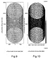
- Figure 9 shows accordingly the sampling pattern for a scene length of almost 4000 km.
- a constant satellite velocity was assumed.
- the sampling points mark the locations at which measured values of the scene are acquired.
- Figure 10 shows the improvement of the temperature resolution as a function of the sampling density per resolution cell.
- the image plane was divided into a regular grid in units of the resolution cell, as is done for image reconstruction.
- the in the middle part of Figure 10 lying darker area represents the normal operating case in which the satellite is already in the phase of continuous data acquisition. In this area, even a temperature resolution of about 1 K can be achieved as far as possible.
- the earth observation scenario described here describes as an example a possible application of a method for measurement of soil moisture and surface salt content of the oceans, for which the protected frequency range of around 1.42 GHz is appropriate.
- the very large (about 30 - 40 m diameter), but fixed main reflector could be realized with the help of foldable or inflatable structures.
- Current activities of ESA and NASA on this application are far from achieving the performance outlined here.
Landscapes
- Engineering & Computer Science (AREA)
- Remote Sensing (AREA)
- Radar, Positioning & Navigation (AREA)
- Physics & Mathematics (AREA)
- Computer Networks & Wireless Communication (AREA)
- General Physics & Mathematics (AREA)
- Electromagnetism (AREA)
- Radar Systems Or Details Thereof (AREA)
- Aerials With Secondary Devices (AREA)
- Variable-Direction Aerials And Aerial Arrays (AREA)
Claims (15)
- Utilisation d'une structure d'antenne directive à réflecteur, mobile, entièrement mécanique, constituée par une antenne à deux réflecteurs, destinée à la représentation bidimensionnelle de scènes (13), par exemple de terrains, d'objets ou de personnes, par une analyse continue en hyperfréquences effectuée au moyen de la structure d'antenne directive à réflecteur, qui est composée d'un réflecteur principal à symétrie de révolution (1), d'une structure d'élément actif d'antenne (3) qui est composée d'un ou de plusieurs éléments actifs d'antenne, et est disposée dans l'axe de symétrie du réflecteur principal qui coïncide avec l'axe optique de la structure d'antenne directive, et d'un réflecteur secondaire (2) à symétrie de révolution, de petites dimensions par rapport au réflecteur principal, et dont l'axe de symétrie est incliné par rapport à l'axe optique de la structure d'antenne directive, utilisation dans laquelle- des premiers moyens d'entraînement (8) sont prévus pour exercer une rotation du réflecteur secondaire, incliné par rapport à l'axe optique de la structure d'antenne directive, sur son sommet autour de l'axe optique de la structure d'antenne directive, et des deuxièmes moyens d'entraînement (17, 18) sont prévus pour exercer un mouvement de l'ensemble de la structure d'antenne directive dans une direction s'étendant au moins à peu près perpendiculairement à la direction de l'axe optique de la structure d'antenne directive,- sur le côté réception, il est prévu un dispositif d'exploitation destiné à créer une image de la scène à partir des hyperfréquences reçues,- la forme du réflecteur principal, la forme du réflecteur secondaire, l'élément actif d'antenne (3), la distance entre l'élément actif d'antenne et le réflecteur secondaire (2) et la distance entre le réflecteur secondaire et le réflecteur principal (1) sont accordés, en tant que paramètres de focalisation dans une analyse à hyperfréquence passive ou active, pour obtenir une focalisation et une taille de champ optique optimales pour une distance à la scène donnée,- les deux moyens d'entraînement (8 ; 17, 18) sont prévus pour obtenir une très grande vitesse de mouvement du réflecteur secondaire par rapport à la vitesse de mouvement de l'ensemble de la structure d'antenne directive,- les paramètres de focalisation et les vitesses de mouvement des deux moyens d'entraînement utilisés pour le balayage continu et sans lacunes de la scène (13) décrivent une tache de focalisation (12) qui se déplace pour la distance respective de la scène (R) sur une trajectoire (22) qui est une combinaison d'une trajectoire (20) résultant de la rotation du réflecteur secondaire et d'une trajectoire (21) résultant du mouvement de la structure d'antenne directive transversalement à son axe optique, et qui présente au moins approximativement la forme d'une cycloïde entrelacée, et- le dispositif d'exploitation côté réception reçoit les données d'image obtenues, grâce à la possibilité de détermination et de ce fait à la connaissance de la trajectoire de la tache de focalisation dans la scène, synchronisées avec la position, les mémorise, les réunit et les représente ou les traite en une image en ligne ou hors ligne.
- Utilisation selon la revendication 1, caractérisée en ce que le premier moyen d'entraînement (8) servant à la production du mouvement de rotation du réflecteur secondaire (2), qui est petit par rapport au réflecteur principal (1), est constitué par un mini-moteur à grande vitesse de rotation placé sur le côté occultation du réflecteur secondaire et ne se trouvant donc pas sur le trajet des rayons.
- Utilisation selon la revendication 1 ou 2, caractérisée en ce que le deuxième moyen d'entraînement (17, 18) est constitué par un entraînement à moteur électrique à effet excentrique, qui met l'ensemble de la structure d'antenne directive en mouvement oscillant dans une direction au moins approximativement perpendiculaire à l'axe optique (7), de sorte qu'avec une amplitude appropriée de l'excursion, on obtient la deuxième dimension d'images.
- Utilisation selon la revendication 1 ou 2, caractérisée en ce que le deuxième moyen d'entraînement est constitué par des entraînements à moteur électrique au moyen desquels l'ensemble de la structure d'antenne directive peut être déplacé dans deux dimensions transversalement à l'axe optique de la structure d'antenne directive, de sorte que la dimension de la scène peut être élargie, ces mouvements étant beaucoup plus lents que le mouvement de rotation du réflecteur secondaire (2).
- Utilisation selon l'une des revendications précédentes, caractérisée en ce que, dans le cas d'une utilisation de plusieurs récepteurs ou systèmes partiels, leurs éléments actifs d'antenne dans la structure d'éléments actifs d'antenne sont disposés symétriquement autour d'un élément actif d'antenne placé sur l'axe optique, central et associé à un des récepteurs ou systèmes partiels, chacun des éléments actifs d'antenne éclairant alors le réflecteur secondaire de façon optimale, et en ce que la disposition géométrique des différents composants de l'ensemble de la structure d'antenne directive, qui comprend plusieurs éléments actifs d'antenne et produit donc des trajectoires différentes les unes des autres dans la scène balayée, est établie en fonction de la distance à la scène afin d'optimiser la focalisation et la taille de champ optique pour tous les systèmes partiels associés respectivement à un élément actif d'antenne.
- Utilisation selon la revendication 5, caractérisée par un dispositif d'analyse destiné à acquérir des images partielles de la scène par les différents récepteurs ou systèmes partiels, les images partielles étant réunies pour donner une représentation complète de toute la scène.
- Utilisation selon les revendications 1 et 5, caractérisée en ce que, dans le dispositif d'exploitation, dans le cas de plusieurs récepteurs ou systèmes partiels, il est prévu un dispositif de formation de moyenne qui transforme les images produites par ces récepteurs ou systèmes partiels en une image définitive conforme au lieu.
- Utilisation selon l'une des revendications précédentes, caractérisée par un étalonnage externe exécuté via un ou plusieurs objets de référence d'intensité connue.
- Utilisation selon l'une des revendications 1 à 7, caractérisée par un étalonnage interne exécuté au moyen d'un commutateur par l'intermédiaire duquel on commute directement, selon l'antenne-source, sur une ou plusieurs sources de référence, de sorte que, de cette façon, l'influence de récepteur qui est la plus dominante est saisie et prise en considération.
- Utilisation selon l'une des revendications précédentes, caractérisée en ce que, dans le dispositif exploitation côté réception, est prévu un dispositif de formation de moyenne dans lequel le balayage irrégulier produit par le principe de prise d'images et la densité irrégulière des valeurs de balayage dans la scène sont transformées, par une formation de moyenne conforme au lieu, pondérée ou non pondérée, sur une grille régulière, en unités de cellules de résolution dans l'espace, comme cela se produit aussi pour la reconstruction ou la production d'images.
- Utilisation selon l'une des revendications précédentes, caractérisée en ce qu'il est prévu, comme éléments actifs d'antenne dans la structure d'éléments actifs d'antenne (3), une ou plusieurs antennes-cornet source à deux fréquences ou plus, qui permettent un fonctionnement simultané dans le cas de deux fréquences de fonctionnement nettement différentes ou plus de deux fréquences de fonctionnement.
- Utilisation selon l'une des revendications précédentes dans le domaine de l'observation terrestre pour des systèmes de mesure depuis le sol destinés à l'acquisition et à la représentation par des techniques de mesure de scénarios à variation rapide dans le temps sur une longue durée, mais aussi soit pour la cartographie de grandes étendues de bandes de terre par exemple pour des applications géophysiques soit pour des reconnaissances tous temps soit comme aide à la navigation par mauvais temps pour avertir de la présence d'obstacles, soit encore pour l'atterrissage.
- Utilisation selon l'une des revendications 1 à 11 dans le domaine de l'observation terrestre par satellite ou véhicule aérien dans lequel, du fait de l'avance régulière de la structure d'antenne directive montée à bord du satellite ou du véhicule aérien et qui peut être pointée vers la surface terrestre, avance qui remplace le mouvement de la structure d'antenne directive transversalement à l'axe optique, il suffit d'un seul réflecteur principal fixe, qui peut de cette façon être de très grande dimension, ce qui donne une haute résolution dans l'espace, ne demande pas à être très rigide mécaniquement et peut donc être réalisé dans une construction légère.
- Utilisation selon l'une des revendications 1 à 11 dans le domaine de la technique de sécurité.
- Utilisation selon la revendication 14 dans un dispositif de surveillance destiné à la protection d'infrastructures critiques, par exemple dans le cadre d'une surveillance tous temps et 24 heures sur 24 d'installations extérieures et/ou dans un système de détection pour objets dissimulés optiquement au niveau de portails ou d'accès, par exemple pour le contrôle des personnes.
Applications Claiming Priority (1)
| Application Number | Priority Date | Filing Date | Title |
|---|---|---|---|
| DE102008013066A DE102008013066B3 (de) | 2008-03-06 | 2008-03-06 | Vorrichtung zur zweidimensionalen Abbildung von Szenen durch Mikrowellen-Abtastung und Verwendung der Vorrichtung |
Publications (3)
| Publication Number | Publication Date |
|---|---|
| EP2099095A1 EP2099095A1 (fr) | 2009-09-09 |
| EP2099095B1 true EP2099095B1 (fr) | 2013-11-20 |
| EP2099095B8 EP2099095B8 (fr) | 2014-03-26 |
Family
ID=40640294
Family Applications (1)
| Application Number | Title | Priority Date | Filing Date |
|---|---|---|---|
| EP09002939.8A Not-in-force EP2099095B8 (fr) | 2008-03-06 | 2009-03-02 | Utilisation d'un dispositif de représentation bidimensionnelle de scènes à l'aide d'un balayage à micro-ondes |
Country Status (3)
| Country | Link |
|---|---|
| US (1) | US8009116B2 (fr) |
| EP (1) | EP2099095B8 (fr) |
| DE (1) | DE102008013066B3 (fr) |
Cited By (2)
| Publication number | Priority date | Publication date | Assignee | Title |
|---|---|---|---|---|
| CN110429371A (zh) * | 2019-08-07 | 2019-11-08 | 中国科学院新疆天文台 | 一种射电望远镜的馈电模式切换机构 |
| US11346938B2 (en) | 2019-03-15 | 2022-05-31 | Msa Technology, Llc | Safety device for providing output to an individual associated with a hazardous environment |
Families Citing this family (33)
| Publication number | Priority date | Publication date | Assignee | Title |
|---|---|---|---|---|
| US8497810B2 (en) * | 2009-03-18 | 2013-07-30 | Kvh Industries, Inc. | Multi-band antenna system for satellite communications |
| US20110084868A1 (en) * | 2009-10-08 | 2011-04-14 | Brijot Imaging Systems, Inc. | Variable range millimeter wave method and system |
| GB201015207D0 (en) * | 2010-09-13 | 2010-10-27 | Radio Physics Solutions Ltd | Improvements in or relating to millimeter and sub-millimeter mave radar-radiometric imaging |
| CA2814635C (fr) | 2010-10-15 | 2019-11-12 | The Invention Science Fund I, Llc | Antennes a diffusion a la surface a champs de rayonnement ajustables |
| DE102011078539A1 (de) * | 2011-06-08 | 2012-12-13 | Rohde & Schwarz Gmbh & Co. Kg | Verfahren und Vorrichtung zur Erweiterung der Ausleuchtung eines Prüfobjekts |
| TW201321789A (zh) * | 2011-11-16 | 2013-06-01 | Ind Tech Res Inst | 成像系統與掃描方法 |
| EP2637253A4 (fr) * | 2011-12-29 | 2014-12-17 | Quantrill Estate Inc | Dispositif universel de concentration d'énergie |
| US10024954B1 (en) * | 2012-11-05 | 2018-07-17 | The United States Of America As Represented By The Secretary Of The Navy | Integrated axial choke rotary offset parabolic reflector |
| US9385435B2 (en) | 2013-03-15 | 2016-07-05 | The Invention Science Fund I, Llc | Surface scattering antenna improvements |
| KR101477199B1 (ko) * | 2013-07-03 | 2014-12-29 | (주)인텔리안테크놀로지스 | 멀티 밴드 스위칭 구조를 갖는 위성 통신용 안테나 |
| US9647345B2 (en) | 2013-10-21 | 2017-05-09 | Elwha Llc | Antenna system facilitating reduction of interfering signals |
| US9923271B2 (en) | 2013-10-21 | 2018-03-20 | Elwha Llc | Antenna system having at least two apertures facilitating reduction of interfering signals |
| US9935375B2 (en) | 2013-12-10 | 2018-04-03 | Elwha Llc | Surface scattering reflector antenna |
| US9871291B2 (en) | 2013-12-17 | 2018-01-16 | Elwha Llc | System wirelessly transferring power to a target device over a tested transmission pathway |
| US9448305B2 (en) * | 2014-03-26 | 2016-09-20 | Elwha Llc | Surface scattering antenna array |
| US9843103B2 (en) | 2014-03-26 | 2017-12-12 | Elwha Llc | Methods and apparatus for controlling a surface scattering antenna array |
| US9711852B2 (en) | 2014-06-20 | 2017-07-18 | The Invention Science Fund I Llc | Modulation patterns for surface scattering antennas |
| US9853361B2 (en) | 2014-05-02 | 2017-12-26 | The Invention Science Fund I Llc | Surface scattering antennas with lumped elements |
| US9882288B2 (en) | 2014-05-02 | 2018-01-30 | The Invention Science Fund I Llc | Slotted surface scattering antennas |
| US10446903B2 (en) | 2014-05-02 | 2019-10-15 | The Invention Science Fund I, Llc | Curved surface scattering antennas |
| US10079424B2 (en) | 2015-09-16 | 2018-09-18 | Viasat, Inc. | Multiple-assembly antenna positioner with eccentric shaft |
| US10361481B2 (en) | 2016-10-31 | 2019-07-23 | The Invention Science Fund I, Llc | Surface scattering antennas with frequency shifting for mutual coupling mitigation |
| CN107015239B (zh) * | 2017-05-19 | 2024-09-17 | 深圳市帝泰光电有限公司 | 一种雷达波穿透成像系统 |
| KR102399539B1 (ko) * | 2017-08-28 | 2022-05-19 | 삼성전자주식회사 | 오브젝트 식별 방법 및 장치 |
| US10658756B1 (en) * | 2017-12-28 | 2020-05-19 | United States Of America As Represented By The Administrator Of Nasa | Earth coverage antenna system for Ka-band communication |
| CN112556852B (zh) * | 2020-06-22 | 2022-03-04 | 西安空间无线电技术研究所 | 星载大口径微波辐射计反射面亮温贡献校正方法及系统 |
| US11901630B1 (en) * | 2020-10-06 | 2024-02-13 | Lockheed Martin Corporation | Confocal phased array fed reflector antenna beam stabilization |
| US20220173797A1 (en) * | 2020-12-01 | 2022-06-02 | Huawei Technologies Co., Ltd. | Satellite dynamic constraints |
| EP4072039B1 (fr) * | 2021-04-07 | 2025-08-27 | The Boeing Company | Système d'antenne confocale alimenté par un réseau d'alimentation reconfigurable qui peut ajuster la taille du faisceau du diagramme de rayonnement et les performances de gain en orbite |
| CN113687313B (zh) * | 2021-07-20 | 2023-12-29 | 西安空间无线电技术研究所 | 一种基于双反射面天线的星载x+s双频sar系统 |
| CN113640758B (zh) * | 2021-08-23 | 2022-07-19 | 中国科学院空天信息创新研究院 | 一种城市复杂环境下的sar图像定标器放置方法与系统 |
| US12584993B2 (en) * | 2021-11-24 | 2026-03-24 | The Regents Of The University Of Michigan | High resolution 4-D millimeter-wave imaging radar |
| AU2023239023A1 (en) * | 2022-03-23 | 2024-09-05 | Kratos Antenna Solutions Corporation | Antenna subreflector with constant phase centering and 3d tracking |
Family Cites Families (13)
| Publication number | Priority date | Publication date | Assignee | Title |
|---|---|---|---|---|
| US3209352A (en) * | 1955-12-28 | 1965-09-28 | Andre G Buck | System for electronic pictorial position comparison |
| FR2412961A1 (fr) | 1977-12-22 | 1979-07-20 | Thomson Csf | Systeme d'antenne a balayage conique pour radar de poursuite |
| US5198827A (en) * | 1991-05-23 | 1993-03-30 | Hughes Aircraft Company | Dual reflector scanning antenna system |
| IT1275349B (it) * | 1994-11-25 | 1997-08-05 | Alenia Spazio Spa | Antenna con fascio ellittico ruotabile con possibilita' di riconfigurazione e zoom del fascio |
| DE19528613C2 (de) * | 1995-08-04 | 1998-07-02 | Daimler Benz Aerospace Ag | Einrichtung zur Bewegungsfehler-Kompensation für ein Radar mit synthetischer Apertur auf der Basis rotierender Antennen (ROSA) für Hubschrauber |
| GB9707654D0 (en) * | 1997-04-16 | 1997-06-04 | Secr Defence | Scanning apparatus |
| GB0104206D0 (en) * | 2001-02-21 | 2001-04-11 | Secr Defence | Radiometers |
| US7194236B2 (en) * | 2001-09-28 | 2007-03-20 | Trex Enterprises Corp. | Millimeter wave imaging system |
| US7385549B2 (en) * | 2003-08-12 | 2008-06-10 | Trex Enterprises Corp | Millimeter wave portal imaging system |
| US6943742B2 (en) * | 2004-02-16 | 2005-09-13 | The Boeing Company | Focal plane array for THz imager and associated methods |
| GB0405105D0 (en) * | 2004-03-05 | 2004-04-07 | Ahmadian Mansour | Phased array imaging system |
| DE202005008250U1 (de) | 2005-05-23 | 2005-09-01 | Xella Trockenbau-Systeme Gmbh | Tunnelausbau |
| DE102005042463A1 (de) | 2005-09-07 | 2007-03-22 | Smiths Heimann Gmbh | Verfahren und Vorrichtung zur Abbildung von Prüfobjekten mittels elektro-magnetischer Wellen, insbesondere zur Kontrolle von Personen auf verdächtige Gegenstände |
-
2008
- 2008-03-06 DE DE102008013066A patent/DE102008013066B3/de not_active Expired - Fee Related
-
2009
- 2009-03-02 EP EP09002939.8A patent/EP2099095B8/fr not_active Not-in-force
- 2009-03-05 US US12/380,962 patent/US8009116B2/en not_active Expired - Fee Related
Cited By (3)
| Publication number | Priority date | Publication date | Assignee | Title |
|---|---|---|---|---|
| US11346938B2 (en) | 2019-03-15 | 2022-05-31 | Msa Technology, Llc | Safety device for providing output to an individual associated with a hazardous environment |
| US12169234B2 (en) | 2019-03-15 | 2024-12-17 | Msa Technology, Llc | Safety device for providing output to an individual associated with a hazardous environment |
| CN110429371A (zh) * | 2019-08-07 | 2019-11-08 | 中国科学院新疆天文台 | 一种射电望远镜的馈电模式切换机构 |
Also Published As
| Publication number | Publication date |
|---|---|
| DE102008013066B3 (de) | 2009-10-01 |
| US8009116B2 (en) | 2011-08-30 |
| EP2099095A1 (fr) | 2009-09-09 |
| EP2099095B8 (fr) | 2014-03-26 |
| US20090224993A1 (en) | 2009-09-10 |
Similar Documents
| Publication | Publication Date | Title |
|---|---|---|
| EP2099095B1 (fr) | Utilisation d'un dispositif de représentation bidimensionnelle de scènes à l'aide d'un balayage à micro-ondes | |
| DE60318075T2 (de) | Echtzeitmillimeterwellenabbildungssystem mittels kreuzkorrelation | |
| DE69902504T2 (de) | Millimeter-Wellen Abbildungssystem mit 360 Grad Sichtfeld | |
| EP3350615B1 (fr) | Capteur lidar | |
| EP0634668B1 (fr) | Dispositif radar pour l'avertissement d'obstacle | |
| EP0578129B1 (fr) | Capteur formateur d'images | |
| EP2293013B1 (fr) | Dispositif de mesure laser en 3D | |
| EP2803951B1 (fr) | Détermination de la topologie pour des matériaux en vrac | |
| DE102004050682B4 (de) | Einrichtung zur Aufnahme eines Objektraumes | |
| WO2017042402A2 (fr) | Capteur laser | |
| EP2126606B1 (fr) | Dispositif pour obtenir l'image d'objets à contrôler au moyen d'ondes électromagnétiques, en particulier pour vérifier si des personnes sont en possession d'objets suspects | |
| EP1566902A1 (fr) | Procédé de transmission d'énergie utilisant des rayons électromagnétiques cohérents | |
| EP1615047A2 (fr) | Méthode de calibration d'un capteur optique de distance monté sur véhicule | |
| DE102008011350A1 (de) | Vorrichtung und Verfahren zur Echtzeiterfassung von elektromagnetischer THz-Strahlung | |
| EP1242829B1 (fr) | Systeme mobile et procede pour caracteriser de maniere etendue et precise des champs de rayonnement a l'exterieur | |
| DE60204212T2 (de) | Radiometer | |
| EP2443437B1 (fr) | Procédé et dispositif de détection d'objets cachés au moyen d'ondes électromagnétiques millimétriques | |
| DE2709570C2 (de) | Ultraschallimpulsechogerät zur hochaufgelösten bildmäßigen Darstellung | |
| DE1541610B2 (de) | Funk-Rückstrahl-Peileinrichtung zur fernsehmäßigen Sichtbarmachung mittels elektronisch abgelenkter Millimeterwellen | |
| EP2361391B1 (fr) | Dispositif et procédé d'imagerie d'un objet par rayonnement électromagnétique haute fréquence | |
| EP3775978B1 (fr) | Dispositif lidar macroscopique | |
| EP3631510B1 (fr) | Dispositif lidar et procédé de balayage d'un angle de balayage au moyen d'au moins un faisceau d'orientation constante | |
| DE60215012T2 (de) | Scan-einrichtung zur bilderzeugung im mikrowellen-, millimeterwellen-, oder infrarot-spektralbereich | |
| DE102016224962B3 (de) | Synthetik-Apertur-Radarverfahren und Synthetik-Apertur-Radarsystem | |
| DE102019200764A1 (de) | Optisches System, insbesondere LiDAR-System, sowie Fahrzeug |
Legal Events
| Date | Code | Title | Description |
|---|---|---|---|
| PUAI | Public reference made under article 153(3) epc to a published international application that has entered the european phase |
Free format text: ORIGINAL CODE: 0009012 |
|
| AK | Designated contracting states |
Kind code of ref document: A1 Designated state(s): AT BE BG CH CY CZ DE DK EE ES FI FR GB GR HR HU IE IS IT LI LT LU LV MC MK MT NL NO PL PT RO SE SI SK TR |
|
| AX | Request for extension of the european patent |
Extension state: AL BA RS |
|
| 17P | Request for examination filed |
Effective date: 20100308 |
|
| AKX | Designation fees paid |
Designated state(s): AT BE BG CH CY CZ DE DK EE ES FI FR GB GR HR HU IE IS IT LI LT LU LV MC MK MT NL NO PL PT RO SE SI SK TR |
|
| RAP1 | Party data changed (applicant data changed or rights of an application transferred) |
Owner name: DEUTSCHES ZENTRUM FUER LUFT- UND RAUMFAHRT E.V. |
|
| 17Q | First examination report despatched |
Effective date: 20110308 |
|
| RIC1 | Information provided on ipc code assigned before grant |
Ipc: H01Q 3/20 20060101ALI20130327BHEP Ipc: H01Q 3/10 20060101AFI20130327BHEP Ipc: H01Q 3/16 20060101ALI20130327BHEP Ipc: G01S 13/42 20060101ALI20130327BHEP Ipc: G01S 13/89 20060101ALI20130327BHEP |
|
| GRAP | Despatch of communication of intention to grant a patent |
Free format text: ORIGINAL CODE: EPIDOSNIGR1 |
|
| INTG | Intention to grant announced |
Effective date: 20130614 |
|
| GRAS | Grant fee paid |
Free format text: ORIGINAL CODE: EPIDOSNIGR3 |
|
| GRAA | (expected) grant |
Free format text: ORIGINAL CODE: 0009210 |
|
| AK | Designated contracting states |
Kind code of ref document: B1 Designated state(s): AT BE BG CH CY CZ DE DK EE ES FI FR GB GR HR HU IE IS IT LI LT LU LV MC MK MT NL NO PL PT RO SE SI SK TR |
|
| REG | Reference to a national code |
Ref country code: GB Ref legal event code: FG4D Free format text: NOT ENGLISH |
|
| REG | Reference to a national code |
Ref country code: CH Ref legal event code: EP |
|
| REG | Reference to a national code |
Ref country code: AT Ref legal event code: REF Ref document number: 642109 Country of ref document: AT Kind code of ref document: T Effective date: 20131215 |
|
| REG | Reference to a national code |
Ref country code: IE Ref legal event code: FG4D Free format text: LANGUAGE OF EP DOCUMENT: GERMAN |
|
| REG | Reference to a national code |
Ref country code: DE Ref legal event code: R096 Ref document number: 502009008354 Country of ref document: DE Effective date: 20140116 |
|
| RBV | Designated contracting states (corrected) |
Designated state(s): AT BE BG CH CY CZ DK EE ES FI FR GB GR HR HU IE IS IT LI LT LU LV MC MK MT NL NO PL PT RO SE SI SK TR |
|
| REG | Reference to a national code |
Ref country code: NL Ref legal event code: VDEP Effective date: 20131120 |
|
| REG | Reference to a national code |
Ref country code: DE Ref legal event code: R108 Ref document number: 502009008354 Country of ref document: DE Effective date: 20131011 |
|
| REG | Reference to a national code |
Ref country code: LT Ref legal event code: MG4D |
|
| PG25 | Lapsed in a contracting state [announced via postgrant information from national office to epo] |
Ref country code: IS Free format text: LAPSE BECAUSE OF FAILURE TO SUBMIT A TRANSLATION OF THE DESCRIPTION OR TO PAY THE FEE WITHIN THE PRESCRIBED TIME-LIMIT Effective date: 20140320 Ref country code: NO Free format text: LAPSE BECAUSE OF FAILURE TO SUBMIT A TRANSLATION OF THE DESCRIPTION OR TO PAY THE FEE WITHIN THE PRESCRIBED TIME-LIMIT Effective date: 20140220 Ref country code: NL Free format text: LAPSE BECAUSE OF FAILURE TO SUBMIT A TRANSLATION OF THE DESCRIPTION OR TO PAY THE FEE WITHIN THE PRESCRIBED TIME-LIMIT Effective date: 20131120 Ref country code: SE Free format text: LAPSE BECAUSE OF FAILURE TO SUBMIT A TRANSLATION OF THE DESCRIPTION OR TO PAY THE FEE WITHIN THE PRESCRIBED TIME-LIMIT Effective date: 20131120 Ref country code: HR Free format text: LAPSE BECAUSE OF FAILURE TO SUBMIT A TRANSLATION OF THE DESCRIPTION OR TO PAY THE FEE WITHIN THE PRESCRIBED TIME-LIMIT Effective date: 20131120 Ref country code: LT Free format text: LAPSE BECAUSE OF FAILURE TO SUBMIT A TRANSLATION OF THE DESCRIPTION OR TO PAY THE FEE WITHIN THE PRESCRIBED TIME-LIMIT Effective date: 20131120 Ref country code: FI Free format text: LAPSE BECAUSE OF FAILURE TO SUBMIT A TRANSLATION OF THE DESCRIPTION OR TO PAY THE FEE WITHIN THE PRESCRIBED TIME-LIMIT Effective date: 20131120 |
|
| PG25 | Lapsed in a contracting state [announced via postgrant information from national office to epo] |
Ref country code: ES Free format text: LAPSE BECAUSE OF FAILURE TO SUBMIT A TRANSLATION OF THE DESCRIPTION OR TO PAY THE FEE WITHIN THE PRESCRIBED TIME-LIMIT Effective date: 20131120 Ref country code: LV Free format text: LAPSE BECAUSE OF FAILURE TO SUBMIT A TRANSLATION OF THE DESCRIPTION OR TO PAY THE FEE WITHIN THE PRESCRIBED TIME-LIMIT Effective date: 20131120 |
|
| PG25 | Lapsed in a contracting state [announced via postgrant information from national office to epo] |
Ref country code: PT Free format text: LAPSE BECAUSE OF FAILURE TO SUBMIT A TRANSLATION OF THE DESCRIPTION OR TO PAY THE FEE WITHIN THE PRESCRIBED TIME-LIMIT Effective date: 20140320 |
|
| PG25 | Lapsed in a contracting state [announced via postgrant information from national office to epo] |
Ref country code: EE Free format text: LAPSE BECAUSE OF FAILURE TO SUBMIT A TRANSLATION OF THE DESCRIPTION OR TO PAY THE FEE WITHIN THE PRESCRIBED TIME-LIMIT Effective date: 20131120 |
|
| PG25 | Lapsed in a contracting state [announced via postgrant information from national office to epo] |
Ref country code: RO Free format text: LAPSE BECAUSE OF FAILURE TO SUBMIT A TRANSLATION OF THE DESCRIPTION OR TO PAY THE FEE WITHIN THE PRESCRIBED TIME-LIMIT Effective date: 20131120 Ref country code: PL Free format text: LAPSE BECAUSE OF FAILURE TO SUBMIT A TRANSLATION OF THE DESCRIPTION OR TO PAY THE FEE WITHIN THE PRESCRIBED TIME-LIMIT Effective date: 20131120 Ref country code: SK Free format text: LAPSE BECAUSE OF FAILURE TO SUBMIT A TRANSLATION OF THE DESCRIPTION OR TO PAY THE FEE WITHIN THE PRESCRIBED TIME-LIMIT Effective date: 20131120 Ref country code: CZ Free format text: LAPSE BECAUSE OF FAILURE TO SUBMIT A TRANSLATION OF THE DESCRIPTION OR TO PAY THE FEE WITHIN THE PRESCRIBED TIME-LIMIT Effective date: 20131120 |
|
| PLBE | No opposition filed within time limit |
Free format text: ORIGINAL CODE: 0009261 |
|
| STAA | Information on the status of an ep patent application or granted ep patent |
Free format text: STATUS: NO OPPOSITION FILED WITHIN TIME LIMIT |
|
| PG25 | Lapsed in a contracting state [announced via postgrant information from national office to epo] |
Ref country code: DK Free format text: LAPSE BECAUSE OF FAILURE TO SUBMIT A TRANSLATION OF THE DESCRIPTION OR TO PAY THE FEE WITHIN THE PRESCRIBED TIME-LIMIT Effective date: 20131120 |
|
| 26N | No opposition filed |
Effective date: 20140821 |
|
| PG25 | Lapsed in a contracting state [announced via postgrant information from national office to epo] |
Ref country code: LU Free format text: LAPSE BECAUSE OF FAILURE TO SUBMIT A TRANSLATION OF THE DESCRIPTION OR TO PAY THE FEE WITHIN THE PRESCRIBED TIME-LIMIT Effective date: 20140302 |
|
| REG | Reference to a national code |
Ref country code: CH Ref legal event code: PL |
|
| REG | Reference to a national code |
Ref country code: IE Ref legal event code: MM4A |
|
| PG25 | Lapsed in a contracting state [announced via postgrant information from national office to epo] |
Ref country code: IE Free format text: LAPSE BECAUSE OF NON-PAYMENT OF DUE FEES Effective date: 20140302 Ref country code: CH Free format text: LAPSE BECAUSE OF NON-PAYMENT OF DUE FEES Effective date: 20140331 Ref country code: LI Free format text: LAPSE BECAUSE OF NON-PAYMENT OF DUE FEES Effective date: 20140331 |
|
| PG25 | Lapsed in a contracting state [announced via postgrant information from national office to epo] |
Ref country code: SI Free format text: LAPSE BECAUSE OF FAILURE TO SUBMIT A TRANSLATION OF THE DESCRIPTION OR TO PAY THE FEE WITHIN THE PRESCRIBED TIME-LIMIT Effective date: 20131120 |
|
| PG25 | Lapsed in a contracting state [announced via postgrant information from national office to epo] |
Ref country code: IT Free format text: LAPSE BECAUSE OF FAILURE TO SUBMIT A TRANSLATION OF THE DESCRIPTION OR TO PAY THE FEE WITHIN THE PRESCRIBED TIME-LIMIT Effective date: 20131120 |
|
| REG | Reference to a national code |
Ref country code: AT Ref legal event code: MM01 Ref document number: 642109 Country of ref document: AT Kind code of ref document: T Effective date: 20140302 |
|
| PG25 | Lapsed in a contracting state [announced via postgrant information from national office to epo] |
Ref country code: AT Free format text: LAPSE BECAUSE OF NON-PAYMENT OF DUE FEES Effective date: 20140302 |
|
| REG | Reference to a national code |
Ref country code: FR Ref legal event code: PLFP Year of fee payment: 8 |
|
| PG25 | Lapsed in a contracting state [announced via postgrant information from national office to epo] |
Ref country code: MT Free format text: LAPSE BECAUSE OF FAILURE TO SUBMIT A TRANSLATION OF THE DESCRIPTION OR TO PAY THE FEE WITHIN THE PRESCRIBED TIME-LIMIT Effective date: 20131120 |
|
| PG25 | Lapsed in a contracting state [announced via postgrant information from national office to epo] |
Ref country code: BG Free format text: LAPSE BECAUSE OF FAILURE TO SUBMIT A TRANSLATION OF THE DESCRIPTION OR TO PAY THE FEE WITHIN THE PRESCRIBED TIME-LIMIT Effective date: 20131120 Ref country code: MC Free format text: LAPSE BECAUSE OF FAILURE TO SUBMIT A TRANSLATION OF THE DESCRIPTION OR TO PAY THE FEE WITHIN THE PRESCRIBED TIME-LIMIT Effective date: 20131120 |
|
| PG25 | Lapsed in a contracting state [announced via postgrant information from national office to epo] |
Ref country code: CY Free format text: LAPSE BECAUSE OF FAILURE TO SUBMIT A TRANSLATION OF THE DESCRIPTION OR TO PAY THE FEE WITHIN THE PRESCRIBED TIME-LIMIT Effective date: 20131120 Ref country code: GR Free format text: LAPSE BECAUSE OF FAILURE TO SUBMIT A TRANSLATION OF THE DESCRIPTION OR TO PAY THE FEE WITHIN THE PRESCRIBED TIME-LIMIT Effective date: 20140221 |
|
| PG25 | Lapsed in a contracting state [announced via postgrant information from national office to epo] |
Ref country code: TR Free format text: LAPSE BECAUSE OF FAILURE TO SUBMIT A TRANSLATION OF THE DESCRIPTION OR TO PAY THE FEE WITHIN THE PRESCRIBED TIME-LIMIT Effective date: 20131120 Ref country code: BE Free format text: LAPSE BECAUSE OF FAILURE TO SUBMIT A TRANSLATION OF THE DESCRIPTION OR TO PAY THE FEE WITHIN THE PRESCRIBED TIME-LIMIT Effective date: 20140331 Ref country code: HU Free format text: LAPSE BECAUSE OF FAILURE TO SUBMIT A TRANSLATION OF THE DESCRIPTION OR TO PAY THE FEE WITHIN THE PRESCRIBED TIME-LIMIT; INVALID AB INITIO Effective date: 20090302 |
|
| REG | Reference to a national code |
Ref country code: FR Ref legal event code: PLFP Year of fee payment: 9 |
|
| REG | Reference to a national code |
Ref country code: DE Ref legal event code: R107 Ref document number: 502009008354 Country of ref document: DE |
|
| REG | Reference to a national code |
Ref country code: FR Ref legal event code: PLFP Year of fee payment: 10 |
|
| PGFP | Annual fee paid to national office [announced via postgrant information from national office to epo] |
Ref country code: GB Payment date: 20180223 Year of fee payment: 10 |
|
| PGFP | Annual fee paid to national office [announced via postgrant information from national office to epo] |
Ref country code: FR Payment date: 20180223 Year of fee payment: 10 |
|
| PG25 | Lapsed in a contracting state [announced via postgrant information from national office to epo] |
Ref country code: MK Free format text: LAPSE BECAUSE OF FAILURE TO SUBMIT A TRANSLATION OF THE DESCRIPTION OR TO PAY THE FEE WITHIN THE PRESCRIBED TIME-LIMIT Effective date: 20131120 |
|
| GBPC | Gb: european patent ceased through non-payment of renewal fee |
Effective date: 20190302 |
|
| PG25 | Lapsed in a contracting state [announced via postgrant information from national office to epo] |
Ref country code: GB Free format text: LAPSE BECAUSE OF NON-PAYMENT OF DUE FEES Effective date: 20190302 |
|
| PG25 | Lapsed in a contracting state [announced via postgrant information from national office to epo] |
Ref country code: FR Free format text: LAPSE BECAUSE OF NON-PAYMENT OF DUE FEES Effective date: 20190331 |