EP2099676B1 - Lagerlose rotorblattanordnung für ein hochgeschwindigkeits-drehflügelflugzeug - Google Patents
Lagerlose rotorblattanordnung für ein hochgeschwindigkeits-drehflügelflugzeug Download PDFInfo
- Publication number
- EP2099676B1 EP2099676B1 EP07875043A EP07875043A EP2099676B1 EP 2099676 B1 EP2099676 B1 EP 2099676B1 EP 07875043 A EP07875043 A EP 07875043A EP 07875043 A EP07875043 A EP 07875043A EP 2099676 B1 EP2099676 B1 EP 2099676B1
- Authority
- EP
- European Patent Office
- Prior art keywords
- rotor blade
- assembly
- rotor
- pitch
- outboard
- Prior art date
- Legal status (The legal status is an assumption and is not a legal conclusion. Google has not performed a legal analysis and makes no representation as to the accuracy of the status listed.)
- Not-in-force
Links
- 238000000034 method Methods 0.000 claims description 5
- 230000004044 response Effects 0.000 claims description 2
- 230000008878 coupling Effects 0.000 description 13
- 238000010168 coupling process Methods 0.000 description 13
- 238000005859 coupling reaction Methods 0.000 description 13
- 230000009977 dual effect Effects 0.000 description 12
- 230000000712 assembly Effects 0.000 description 3
- 238000000429 assembly Methods 0.000 description 3
- 230000008901 benefit Effects 0.000 description 3
- 238000007789 sealing Methods 0.000 description 3
- 238000012546 transfer Methods 0.000 description 3
- 230000007704 transition Effects 0.000 description 3
- 238000005452 bending Methods 0.000 description 2
- 125000004122 cyclic group Chemical group 0.000 description 2
- 230000000694 effects Effects 0.000 description 2
- 238000012986 modification Methods 0.000 description 2
- 230000004048 modification Effects 0.000 description 2
- OKTJSMMVPCPJKN-UHFFFAOYSA-N Carbon Chemical compound [C] OKTJSMMVPCPJKN-UHFFFAOYSA-N 0.000 description 1
- 229910000831 Steel Inorganic materials 0.000 description 1
- 238000013459 approach Methods 0.000 description 1
- 102220346563 c.259A>T Human genes 0.000 description 1
- 230000015556 catabolic process Effects 0.000 description 1
- 230000008859 change Effects 0.000 description 1
- 239000002131 composite material Substances 0.000 description 1
- 238000006731 degradation reaction Methods 0.000 description 1
- 238000013461 design Methods 0.000 description 1
- 229910002804 graphite Inorganic materials 0.000 description 1
- 239000010439 graphite Substances 0.000 description 1
- 230000020169 heat generation Effects 0.000 description 1
- 230000006872 improvement Effects 0.000 description 1
- 230000010354 integration Effects 0.000 description 1
- 239000000463 material Substances 0.000 description 1
- 230000007246 mechanism Effects 0.000 description 1
- 230000001141 propulsive effect Effects 0.000 description 1
- 239000010959 steel Substances 0.000 description 1
Images




Classifications
-
- B—PERFORMING OPERATIONS; TRANSPORTING
- B64—AIRCRAFT; AVIATION; COSMONAUTICS
- B64C—AEROPLANES; HELICOPTERS
- B64C27/00—Rotorcraft; Rotors peculiar thereto
- B64C27/04—Helicopters
- B64C27/08—Helicopters with two or more rotors
- B64C27/10—Helicopters with two or more rotors arranged coaxially
-
- B—PERFORMING OPERATIONS; TRANSPORTING
- B64—AIRCRAFT; AVIATION; COSMONAUTICS
- B64C—AEROPLANES; HELICOPTERS
- B64C27/00—Rotorcraft; Rotors peculiar thereto
- B64C27/32—Rotors
-
- B—PERFORMING OPERATIONS; TRANSPORTING
- B64—AIRCRAFT; AVIATION; COSMONAUTICS
- B64C—AEROPLANES; HELICOPTERS
- B64C27/00—Rotorcraft; Rotors peculiar thereto
- B64C27/32—Rotors
- B64C27/33—Rotors having flexing arms
-
- B—PERFORMING OPERATIONS; TRANSPORTING
- B64—AIRCRAFT; AVIATION; COSMONAUTICS
- B64C—AEROPLANES; HELICOPTERS
- B64C27/00—Rotorcraft; Rotors peculiar thereto
- B64C27/32—Rotors
- B64C27/46—Blades
- B64C27/473—Constructional features
-
- B—PERFORMING OPERATIONS; TRANSPORTING
- B64—AIRCRAFT; AVIATION; COSMONAUTICS
- B64C—AEROPLANES; HELICOPTERS
- B64C27/00—Rotorcraft; Rotors peculiar thereto
- B64C27/32—Rotors
- B64C27/46—Blades
- B64C27/473—Constructional features
- B64C27/48—Root attachment to rotor head
-
- B—PERFORMING OPERATIONS; TRANSPORTING
- B64—AIRCRAFT; AVIATION; COSMONAUTICS
- B64C—AEROPLANES; HELICOPTERS
- B64C27/00—Rotorcraft; Rotors peculiar thereto
- B64C27/32—Rotors
- B64C27/46—Blades
- B64C27/473—Constructional features
- B64C27/50—Blades foldable to facilitate stowage of aircraft
-
- B—PERFORMING OPERATIONS; TRANSPORTING
- B64—AIRCRAFT; AVIATION; COSMONAUTICS
- B64C—AEROPLANES; HELICOPTERS
- B64C27/00—Rotorcraft; Rotors peculiar thereto
- B64C27/54—Mechanisms for controlling blade adjustment or movement relative to rotor head, e.g. lag-lead movement
- B64C27/58—Transmitting means, e.g. interrelated with initiating means or means acting on blades
Definitions
- the present invention relates to a bearingless rotor blade assembly of a rotary-wing aircraft, and more particularly to a flexbeam assembly having a first beam and a second beam with a pitch shaft channeled therebetween, the beams extend to a radial outboard station of the rotor blade at which the pitch shaft ends and the beams morph into a rotor blade spar.
- a rotary wing aircraft with a contra-rotating rigid rotor system is capable of higher speeds compared to conventional single rotor helicopters due in part to the balance of lift between the advancing sides of the main rotor blades on the upper and lower rotor systems.
- Aerodynamic drag associated with a rotary wing aircraft having a counter-rotating, coaxial rotor system is primarily due to the additional rotor hub and the interconnecting main rotor shaft assembly between the upper and lower rotor systems.
- the increased drag resulting from the counter-rotating, coaxial rotor system may result in a relatively significant power penalty.
- the aerodynamic drag of the dual counter-rotating, coaxial rotor system may be reduced by a rotor fairing system.
- sealing compatibility of the rotor fairing system with the rotor blades may be complicated by a relatively thick inboard airfoil section typical of conventional flexbeam rotor systems having an airfoil shaped torque tube that surrounds a flexbeam which receive a pitch input.
- Sealing with the rotor fairing system may be further complicated by a rotor control system which provides a pitch input to each rotor blade at a location typically adjacent to the interface between the rotor fairing system and each rotor blade.
- a known system with dual flexbeam and a pitch shaft arranged therebetween as applied to single rotor helicopters is shown in FR-A-2374212 .
- the advance ratio is sufficiently high such that a significant part of the retreating blade is in reverse flow.
- the inboard section of the rotor blade has an angle of attack well beyond stall, producing significant negative lift and high drag force.
- the angle of attack beyond stall, flapping clearances, rotor control system pitch input clearances, and the relatively thick inboard airfoil all combine to complicate fairing system integration and result in degradation of the rotor system lift/drag ratio.
- the invention concerns a rotor blade assembly and associated pitch control method as defined in independent claims 1 and 6.
- a bearingless rotor system includes a flexbeam assembly having a first beam and a second beam arranged in a back-to-back orientation with a pitch shaft channeled therebetween.
- the beams extend to an outboard rotor blade station, at which the beams may preferably morph into a rotor blade spar within an outboard rotor blade section.
- Both the flexbeam assembly and the outboard rotor blade section may preferably be surrounded by an essentially contiguous outer aerodynamic skin which provides an aerodynamic surface, but minimizes torsional stiffness effect which may resist pitch change.
- the outboard section of the flexbeam assembly reflects the full pitch input from the pitch shaft while the most inboard section of the flexbeam assembly is essentially fixed in pitch by a blade attachment to a rotor hub assembly. That is, the flexbeam assembly twist versus span is essentially linear from the innermost to the outermost station.
- the outboard rotor blade section extends from the flexbeam assembly and reflects the pitch input to the rotor blade tip.
- the pitch shaft provides a direct pitch input into the flexbeam assembly at a relative soft section that replaces the heretofore required bulky torque tube with the outer aerodynamic skin which need not be much larger than the flexbeam assembly itself. This is especially advantageous in a high-speed rotary-wing aircraft in which the inboard sections of the retreating blades are in reverse flow such that having a non-pitching inboard blade section results in a thin, low-drag airfoil which is readily received in a sealed relationship with a rotor hub fairing system.
- the present invention therefore provides a rotor blade for a high speed rotary-wing aircraft flight envelope.
- Said pitch shaft may be mounted within at least one bearing between said first beam and said second beam.
- the assembly may further comprise an outboard rotor blade section outboard of said pitch shaft outboard section.
- Said first beam may morph into said first rotor blade spar and said second beam may morph into said second rotor blade spar in a region adjacent to said outboard rotor blade station.
- the assembly may further comprise an outer aerodynamic skin mounted to said first beam and said second beam, said outer aerodynamic skin includes a multiple of resilient joints to minimize a torsional stiffness thereof.
- a method of pitching a rotor blade assembly of a rotary-wing aircraft may, according to an embodiment, comprise:
- Said step (B) may further comprise:
- Said step (A) may further comprise:
- FIG 1A illustrates an exemplary vertical takeoff and landing (VTOL) rotary-wing aircraft 10 having a dual, counter-rotating, coaxial rotor system 12 which rotates about an axis of rotation A.
- the aircraft 10 includes an airframe 14 which supports the dual, counter rotating, coaxial rotor system 12 as well as a propulsive system T which provides translational thrust generally parallel to an aircraft longitudinal axis.
- VTOL vertical takeoff and landing
- the dual, counter-rotating, coaxial rotor system 12 includes an upper rotor system 16 and a lower rotor system 18.
- Each rotor system 16, 18 includes a plurality of rotor blade assemblies 20 mounted to each of an upper rotor hub assembly 22 and a lower rotor hub assembly 24 for rotation about the rotor axis of rotation A. It should be understood that any number of rotor blade assemblies 20 may be mounted to each rotor hub assembly 22, 24.
- the rotor system 12 preferably includes a rotor hub fairing system Fh generally located between and around the upper and lower rotor systems 16, 18 such that the rotor hub assemblies 22, 24 are at least partially contained therein.
- the rotor hub fairing system Fh includes an upper hub fairing Fu, a lower hub fairing Fl and a shaft fairing Fs therebetween.
- the shaft fairing Fs is attached to the counter-rotating, coaxial rotor system 12 through a bearing arrangement Bu, Bl such that the shaft fairing Fs is aligned with the relative wind in forward flight but may be free to pivot during low speed maneuvering.
- the upper bearing Bu and the lower bearing Bl are respectively located adjacent an upper portion and a lower portion of the shaft fairing Fs.
- the upper bearing Bu is preferably attached to one rotor shaft 12U while the lower bearing Bl attached to the other rotor shaft 12L such that the bearings counter-rotate and net bearing drag is relatively low.
- each rotor blade assembly 20 includes a blade attachment 26 which serves as the structural link to the rotor hub assembly 22, 24 and preferably permits blade fold ( Figure 3B ). It should be understood that various blade fold attachments may also be utilized with the present invention.
- Each blade attachment 26 is mounted to a flexbeam assembly 28 having a first beam 30A and a second beam 30B arranged in a back-to-back orientation with a pitch shaft 32 channeled therebetween.
- the beams 30A, 30B preferably extend to 46% of the rotor radius at which the beams 30A, 30B morph into a rotor blade spar.
- the upper rotor system 16 includes an upper rotor control system 36 ( Figure 3E ) and the lower rotor system 18 includes a lower rotor control system 38 ( Figure 3D ).
- a pitch control coupling assembly 40 (best seen in Figure 3C ) for each rotor blade assembly 20 includes a blade pitch control coupling 42 mounted for rotation with the pitch shaft 32 and a horn spindle coupling 44 rotationally mounted to the rotor hub assembly 22, 24.
- the blade pitch control coupling 42 rotationally engages the horn spindle coupling 44 at an interface 45 when the blade attachment 26 is in the flight position ( Figure 3A ).
- the interface 45 may be a toothed interface as best illustrated in Figure 3D or another interface to rotationally lock the blade pitch control coupling 42 with the horn spindle coupling 44 such that a pitch input to the horn spindle coupling 44 is transmitted to the blade pitch control coupling 42, the pitch shaft 32 and the flexbeam assembly 28.
- the lower rotor control system 38 includes a pitch control rod 46 for each rotor blade assembly 20 that is linked with the horn spindle coupling 44 through a pitch control horn 48 to impart the desired pitch control to the pitch shaft 32 from a lower swashplate 50 ( Figure 2 ) or the like.
- the pitch control rod 46 may be located either internal or external the main rotor shaft of the rotor system 12.
- the pitch control rods 46 are external to the main rotor shaft 12L for pitch control of the lower rotor system 18 and internal to the main rotor shaft 12U for pitch control of the upper rotor system 16.
- the upper rotor control system 36 is preferably contained within the upper rotor shaft 12U which counter-rotates relative the lower rotor shaft 12L.
- the upper rotor control system 36 generally includes a relatively large diameter push rod 52 that is attached to a collective servo 54 at one end and to a pitch beam 56 at the other.
- the pitch beam 56 is connected to a pitch control horn 58 of the horn spindle coupling 44 to impart the desired pitch control to the pitch shaft 32 of each upper rotor blade assembly 20.
- the pitch control horn 58 and horn spindle coupling 44 are generally equivalent on both the upper and lower rotor system 16, 18.
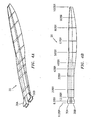
- pitch inputs from the upper rotor system 16 and the lower rotor system 18 are transmitted to the respective rotor blade assembly 20 by the pitch shaft 32 channeled between the beams 30A, 30B and rigidly attached at an outboard rotor blade station which is preferably the 0.46R station ( Figure 4B ). It should be understood that the pitch shaft 32 may be attached at other radial stations.
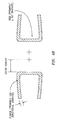
- the beams 30A, 30B are preferably torsional-soft structures having a C-section ( Figure 4C ).
- the C-section of the beams 30A, 30B allow for an elegant solution to high flapping stiffness requirements. This arrangement results in a structure with high stiffness without resorting to thick laminates, which may be of relatively significant weight.
- the material of the beams 30A, 30B are preferably tailored across the cross-section to achieve the desired behavior with the flanges being soft in torsion (mainly uni-directional plies) and the shear web being stiffer to react the shears that develop in that region ( Figure 4D ). It should be understood that other cross-sections such as rectangular beams and I-beams may be utilized depending on a desired flap-softness and torsional stiffness.
- the beams 30A, 30B are spread apart to recover the pitch shaft 32 therebetween. This spacing also serves the purpose of moving the shear centers of the two beams closer to each other thus resulting in the softest option of the combined beams (see Figure 4D ).
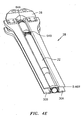
- the pitch shaft 32 provides a direct pitch input into the flexbeam assembly 28 at a relative soft section and replaces the heretofore required bulky torque tube with an efficient aerodynamic blade skin 68 ( Figure 4F ) which need not be much larger than the flexbeam assembly 28 itself.
- This is especially advantageous in a high-speed rotary-wing aircraft in which the inboard sections of the retreating blade is in reverse flow as having a non-pitching airfoil results in a low-drag inboard section which is readily received in a sealed relationship with the respective upper hub fairing Fu and the lower hub fairing Fl ( Figure 2 ).
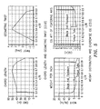
- the blade characteristics provided by the blade skin 68 may take various forms other than that which is preferred ( Figure 5 ).
- the pitch shaft 32 is preferably a composite hollow tubular structure, which in one example is approximately 21 ft in length with an outer diameter of 10 inches and an average wall thickness of 0.5 inches. Due to the length and the function of the pitch shaft 32, the main design constraint is torsional stiffness. Shaft windup is preferably limited to one degree under the loads corresponding to 245 Kts cruise. For one embodiment of the flexbeam assembly 28, the pitch shaft 32 may be subjected to a maximum moment of 220,000 1b-in. This stiffness requirement is readily met by high modulus graphite (M60J) arranged in a ⁇ 45° orientation providing a stiffness comparable to steel at 1/6 its weight. The lower strain allowable of MJ70 as compared to IM7 is not a concern since the stiffness requirement results in low-strained structure.
- M60J modulus graphite
- the pitch shaft 32 is preferably constrained by two self-lubricating bearings 64A, 64B (also illustrated in Figure 4G ).
- One bearing 64A is housed within the blade attachment 26 and the other bearing 64B is attached to the beams 30A, 30B.
- These bearings 64A, 64B serve a purpose similar to a snubber in a conventional torque-tube configuration and maintain the pitch shaft 32 coaxial with the blade pitch control coupling 42.
- Self-lubricating liners are well suited for this application due to the relatively low loads and small radius involved. With a spacing of 50 inches between the two bearings the maximum load required to react the combined flapping and chordwise moments and shears originating from the pitch shaft 32 is approximately 5,622 lb ( Figure 4G ).
- the PV (effectively, power per unit area) is 7,028 psi-ft/min, which is well within the operating range of KAtherm T87S liners manufactured by Kamatics Corporation (a subsidiary of Kaman Corporation of Bloomfield, CT USA).
- Kamatics Corporation a subsidiary of Kaman Corporation of Bloomfield, CT USA.
- the heat generated at each bearing is estimated at 450 BTU/hr, which is comparable with the heat generation of typical pitch rod bearings (about 174 BTU/hr).
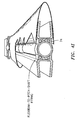
- the rotor blade assembly 20 preferably defines the flexbeam assembly 28 inboard of 0.46R and an outboard rotor blade section 66 outboard of 0.46R. That is, outboard of the 0.46R region, the beams 30A, 30B function as a forward and an aft web of a tubular spar ( Figure 4C ). It should be understood that although the flexbeam to spar transition is illustrated at approximately 0.46R in the disclosed embodiment, other outboard rotor blade stations will likewise be usable with the present invention.
- the flexbeam assembly 28 and the outboard rotor blade section 66 are surrounded by the essentially contiguous outer aerodynamic blade skin 68.
- the outer aerodynamic blade skin 68 may include one or more sections to define a particular and changing airfoil at various span-wise sections ( Figure 4C ).
- the outer aerodynamic blade skin 68 is attached to the flexbeam assembly 28, so the pitch motion of the rotor blade assembly 20 received at any rotor blade station is generally equal to the elastic angle of the flexbeam assembly 28 at that rotor blade station.
- the outer aerodynamic blade skin 68 is preferably elastically mounted to the flexbeam assembly 28 to provide minimum torsional stiffness to the flexbeam assembly 28 and preferably may include a multiple or resilient joints 70 to minimize any torsional stiffness effect ( Figure 4H ).
- a shell laminate 72 forms an upper plate and a lower plate between the beams 30A, 30B to form a tubular torque box.
- 0° and 45° plies are gradually added to the shell laminate 72 as they begin to carry more of the bending and torsion loads.
- the beams 30A, 30B are preferably bonded to the outer aerodynamic blade skin 68 to transfer the flatwise bending stresses from the flanges of the beams 30A, 30B into a thickened region of the shell laminate 72 between the beams 30A, 30B to pitch the outboard rotor blade section 66.
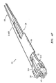
- the pitch tube 32 preferably terminates at 0.46R, and is locally attached through a pitch shaft fitting 74 ( Figure 4I ) outboard of the two self-lubricating bearings 64A, 64B, to the beams 30A, 30B to transfer the torsion therefrom.
- the shell laminate 72 thickness is preferably increased at in the 0.46R region to support the loads from the pitch shaft fitting 74 which transfers the torsional forces from the pitch tube 32 to the beams 30A, 30B.
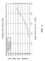
- the outboard section of the flexbeam assembly 28 receives the full pitch input from the pitch shaft 32 while the most inboard section of the flexbeam assembly 28 is essentially fixed in pitch by the blade attachment 26 to the rotor hub assembly 22, 24. That is, the flexbeam assembly 28 twist versus span is essentially linear from 0.0R to 0.46R ( Figure 6 ).
- the outboard rotor blade section 66 thereby also defines the pitch input from the 0.46R station to the rotor blade tip equivalent to that at the 0.46R station. In other words, the entire outboard rotor blade section is at the same pitch as the outermost station of the flexbeam assembly 28 where the pitch shaft 32 is attached through the pitch shaft fitting 74.
- the beams 30A, 30B and pitch tube 32 arrangement allows the innermost sections of the flexbeam assembly 28 to avoid the pitch interference relationship and resultant thicker airfoil of a conventional flexbeam rotor blade such that a relatively thinner inboard airfoil may be utilized to provide a significant performance improvement for high speed bearingless rotors. Furthermore, as the innermost sections of the flexbeam assembly 28 is essentially fixed in pitch, the present invention facilitates rotor hub fairing sealing with the rotor control system, the rotor blade assembly and the rotor blade fold mechanism to minimizing critical hub drag and maximize aircraft high speed performance.
Landscapes
- Engineering & Computer Science (AREA)
- Mechanical Engineering (AREA)
- Aviation & Aerospace Engineering (AREA)
- Wind Motors (AREA)
- Structures Of Non-Positive Displacement Pumps (AREA)
- Turbine Rotor Nozzle Sealing (AREA)
- Tires In General (AREA)
Claims (8)
- Rotorblattanordnung umfassend:einen ersten Holm (30A);einen zweiten Holm (30B);eine Anstellwinkelwelle (32), die rotationsmäßig zwischen dem ersten Holm (30A) und dem zweiten Holm (30B) angebracht ist, wobei die Anstellwinkelwelle (32) einen Anstellwinkelwellen-Außenbereich aufweist, der direkt an dem ersten Holm (30A) und dem zweiten Holm (30B) an einer Rotorblatt-Au-βenposition angebracht ist, so dass eine Anstellwinkeleingabe in einen Innenbereich der Anstellwinkelwelle (32) den ersten Holm (30A) und den zweiten Holm (30B) an der Rotorblatt-Außenposition verdreht;gekennzeichnet durcheine Blattanbringung (26), die dazu ausgebildet ist, die Rotorblattanordnung an einer Rotornabenanordnung anzubringen, und die mit dem ersten Holm (30A) und dem zweiten Holm (30B) verbunden ist, wobei sich die Anstellwinkelwelle (32) durch die Blattanbringung erstreckt.
- Anordnung nach Anspruch 1, wobei die Anstellwinkelwelle (32) innerhalb zumindest eines Lagers (64A, 64B) zwischen dem ersten Holm (30A) und dem zweiten Holm (30B) angebracht ist.
- Anordnung nach Anspruch 1 oder 2, des Weiteren umfassend einen Rotorblatt-Außenbereich (66) außerhalb des Anstellwinkelwellen-Außenbereichs (32).
- Anordnung nach einem der Ansprüche 1 bis 3, wobei der erste Holm (30A) in den ersten Rotorblattspannten und der zweite Holm (30B) in den zweiten Rotorblattspannten übergeht in einen Bereich benachbart zu der Rotorblatt-Au-βenposition.
- Anordnung nach einem der Ansprüche 1 bis 4, des Weiteren umfassend eine aerodynamische Außenhaut, die an dem ersten Holm (30A) und dem zweiten Holm (30B) angebracht ist, wobei die aerodynamische Außenhaut eine Vielzahl von elastischen Verbindungen beinhaltet, um eine Torsionssteifheit von dieser zu minimieren.
- Verfahren zum Anstellen einer Rotorblattanordnung eines Drehflügel-Flugzeugs, umfassend:(A) Eingeben einer Torsionseingabe in eine Anstellwinkelwelle (32) an einem Anstellwinkelwellen-Innenbereich (32) an einer Wurzel der Rotorblattanordnung, wobei die Anstellwinkelwelle (32) direkt an einer Rotorblatt-Außenposition an einem ersten Holm (30A) und einem zweiten Holm (30B) angebracht ist; und(B) Verdrehen des ersten Holms (30A) und des zweiten Holms (30B) an der Rotorblatt-Außenposition in Erwiderung auf Schritt (A), wobei sich die Anstellwinkelwelle (32) durch eine Blattanbringung (26) erstreckt, die die Rotorblattanordnung an eine Rotornabenanordnung anbringt und mit dem ersten Holm (30A) und dem zweiten Holm (30B) verbunden ist.
- Verfahren nach Anspruch 6, wobei der Schritt (B) des Weiteren umfasst:(a) Verdrehen des ersten Holms (30A) und des zweiten Holms auf eine im Wesentlichen lineare Weise von einer Rotorblatt-Innenposition zu einer Rotorblatt-Außenposition.
- Verfahren nach Anspruch 6 oder 7, wobei der Schritt (A) des Weiteren umfasst:Eingeben der Torsionseingabe durch eine Anstellwinkelsteuerungs/Regelungs-Anordnung der Rotornabenanordnung.
Applications Claiming Priority (2)
| Application Number | Priority Date | Filing Date | Title |
|---|---|---|---|
| US11/565,669 US7695249B2 (en) | 2006-12-01 | 2006-12-01 | Bearingless rotor blade assembly for a high speed rotary-wing aircraft |
| PCT/US2007/084394 WO2008147449A2 (en) | 2006-12-01 | 2007-11-12 | Bearingless rotor blade assembly for a high speed rotary-wing aircraft |
Publications (2)
| Publication Number | Publication Date |
|---|---|
| EP2099676A2 EP2099676A2 (de) | 2009-09-16 |
| EP2099676B1 true EP2099676B1 (de) | 2011-12-21 |
Family
ID=39514130
Family Applications (1)
| Application Number | Title | Priority Date | Filing Date |
|---|---|---|---|
| EP07875043A Not-in-force EP2099676B1 (de) | 2006-12-01 | 2007-11-12 | Lagerlose rotorblattanordnung für ein hochgeschwindigkeits-drehflügelflugzeug |
Country Status (4)
| Country | Link |
|---|---|
| US (1) | US7695249B2 (de) |
| EP (1) | EP2099676B1 (de) |
| AT (1) | ATE538028T1 (de) |
| WO (1) | WO2008147449A2 (de) |
Cited By (1)
| Publication number | Priority date | Publication date | Assignee | Title |
|---|---|---|---|---|
| US9457889B2 (en) | 2013-09-24 | 2016-10-04 | The Boeing Company | Rotorcraft rotor including primary pitch horns and secondary horns |
Families Citing this family (28)
| Publication number | Priority date | Publication date | Assignee | Title |
|---|---|---|---|---|
| US8608441B2 (en) | 2006-06-12 | 2013-12-17 | Energyield Llc | Rotatable blade apparatus with individually adjustable blades |
| US9169011B2 (en) | 2011-09-13 | 2015-10-27 | Sikorsky Aircraft Corporation | Rotor with blades including outer blade shell and inner structural member |
| CN102887222A (zh) * | 2012-09-18 | 2013-01-23 | 北京理工大学 | 一种扭角分布可变的桨叶 |
| US9051047B2 (en) * | 2012-11-12 | 2015-06-09 | Sikorsky Aircraft Corporation | Flexbeam rotor attachment to rotor blade |
| US9487291B2 (en) * | 2012-12-05 | 2016-11-08 | The Boeing Company | Apparatus, system, and method for pitching and twisting a blade of a rotorcraft |
| US20140308123A1 (en) * | 2013-04-11 | 2014-10-16 | Sikorsky Aircraft Corporation | Bearing for rotor blade |
| GB201307066D0 (en) * | 2013-04-18 | 2013-05-29 | Airbus Operations Ltd | Winglet and braided composite spar |
| US9428268B2 (en) | 2013-07-02 | 2016-08-30 | Sikorsky Aircraft Corporation | Flexbeam hinge for helicopter blade active trailing edge flap |
| US9315265B2 (en) * | 2013-07-29 | 2016-04-19 | Sikorsky Aircraft Corporation | Adjustable scissor control link |
| US9533754B2 (en) | 2014-04-19 | 2017-01-03 | The Boeing Company | Wing aerial refueling system |
| US10793264B2 (en) * | 2014-06-27 | 2020-10-06 | Sikorsky Aircraft Corporation | Flex beam clamp for rotor assembly |
| EP3177525B1 (de) | 2014-08-08 | 2020-03-11 | Sikorsky Aircraft Corporation | Flexibler träger für rotoranordnung |
| WO2016057255A1 (en) * | 2014-09-29 | 2016-04-14 | Sikorsky Aircraft Corporation | Integrated main rotor hub and shaft |
| US10336447B2 (en) * | 2014-12-02 | 2019-07-02 | Bell Helicopter Textron Inc. | Folding proprotor gimbal lock and blade lock mechanism |
| US11235858B2 (en) | 2014-12-02 | 2022-02-01 | Textron Innovations Inc. | Blade fold mechanism |
| US10160540B2 (en) * | 2015-01-09 | 2018-12-25 | Rohr, Inc. | Rotor head for a vertical takeoff and landing aircraft |
| US9758242B2 (en) | 2015-02-04 | 2017-09-12 | Sikorsky Aircraft Corporation | Lift offset management and control systems for coaxial rotorcraft |
| US10145244B2 (en) * | 2015-07-06 | 2018-12-04 | Bell Helicopter Textron Inc. | Rotorcraft rotor blade assembly |
| US10899438B2 (en) | 2015-11-12 | 2021-01-26 | Sikorsky Aircraft Corporation | Seals for rotor system fairings |
| EP3225542B1 (de) | 2016-03-30 | 2018-05-09 | AIRBUS HELICOPTERS DEUTSCHLAND GmbH | Verfahren zur herstellung einer kontrollmanschette für ein rotorblatt eines scharnier- und lagerlosen rotors |
| US10618632B2 (en) * | 2017-02-13 | 2020-04-14 | Bell Helicopter Textron Inc. | Foldable rotor blade assembly |
| US11225324B2 (en) | 2019-05-17 | 2022-01-18 | Lockheed Martin Corporation | Dual flex-beam assembly for folding rotor blade |
| US10858096B1 (en) * | 2019-05-29 | 2020-12-08 | Lockheed Martin Corporation | Folding horn concept for rigid rotor blade fold |
| US11299265B2 (en) * | 2019-05-30 | 2022-04-12 | Lockheed Martin Corporation | Rotor blade folding system |
| CN111434582A (zh) * | 2020-04-01 | 2020-07-21 | 深圳市科卫泰实业发展有限公司 | 一种共轴双桨八旋翼大载重无人机 |
| US11753156B2 (en) * | 2020-07-15 | 2023-09-12 | Lockheed Martin Corporation | Main rotor blade using integral metallic center block strap assembly |
| US11498669B1 (en) * | 2021-04-27 | 2022-11-15 | Lockheed Martin Corporation | Rotor system |
| US11884387B2 (en) | 2021-12-21 | 2024-01-30 | Lockheed Martin Corporation | Rotor assembly connectable to rotor hub and having pitch control |
Family Cites Families (12)
| Publication number | Priority date | Publication date | Assignee | Title |
|---|---|---|---|---|
| FR1084706A (fr) | 1953-06-11 | 1955-01-24 | Sncaso | Voilure tournante, en particulier pour hélicoptère |
| FR1305631A (fr) | 1961-09-12 | 1962-10-05 | Dornier Werke Gmbh | Dispositif de suspension pour pales d'hélice commandées par réaction |
| DE1169306B (de) | 1962-10-06 | 1964-04-30 | Dornier Werke Gmbh | Einrichtung zum Aufhaengen von Luftschrauben-blaettern unter Verwendung von Federpaketen |
| DE1275871B (de) | 1965-09-08 | 1968-08-22 | Dornier Gmbh | Hubschrauberrotor mit zwei an laminierten Federpaketen aufgehaengten Rotorblaettern |
| GB1189136A (en) | 1969-10-17 | 1970-04-22 | Agusta Aeronaut Costr | Rotor Head for a Mechanically Driven Helicopter |
| US4111605A (en) | 1976-12-16 | 1978-09-05 | The Boeing Company | Composite hingeless rotor hub for rotary wing aircraft |
| US4316700A (en) | 1979-04-03 | 1982-02-23 | Schramm Burford J | Unitary, bonded-together helicopter rotorblade |
| US4403918A (en) * | 1979-04-03 | 1983-09-13 | Schramm Buford J | Hubless, hingeless and bearingless helicopter rotor system |
| US4419051A (en) | 1982-02-16 | 1983-12-06 | The Boeing Company | Twin tension/torsion beam rotor system |
| DE3332417C2 (de) | 1983-09-08 | 1986-04-03 | Messerschmitt-Bölkow-Blohm GmbH, 8012 Ottobrunn | Rotor, insbesondere für Drehflügelflugzeuge |
| US4580945A (en) | 1984-09-27 | 1986-04-08 | United Technologies Corporation | Helicopter gimbal rotor |
| US4792280A (en) | 1987-04-27 | 1988-12-20 | United Technologies Corporation | Helicopter rotor flexbeam |
-
2006
- 2006-12-01 US US11/565,669 patent/US7695249B2/en active Active
-
2007
- 2007-11-12 EP EP07875043A patent/EP2099676B1/de not_active Not-in-force
- 2007-11-12 AT AT07875043T patent/ATE538028T1/de active
- 2007-11-12 WO PCT/US2007/084394 patent/WO2008147449A2/en not_active Ceased
Cited By (1)
| Publication number | Priority date | Publication date | Assignee | Title |
|---|---|---|---|---|
| US9457889B2 (en) | 2013-09-24 | 2016-10-04 | The Boeing Company | Rotorcraft rotor including primary pitch horns and secondary horns |
Also Published As
| Publication number | Publication date |
|---|---|
| WO2008147449A2 (en) | 2008-12-04 |
| EP2099676A2 (de) | 2009-09-16 |
| US7695249B2 (en) | 2010-04-13 |
| ATE538028T1 (de) | 2012-01-15 |
| US20080131280A1 (en) | 2008-06-05 |
| WO2008147449A3 (en) | 2009-04-16 |
Similar Documents
| Publication | Publication Date | Title |
|---|---|---|
| US7695249B2 (en) | Bearingless rotor blade assembly for a high speed rotary-wing aircraft | |
| US8864062B2 (en) | Aircraft with integrated lift and propulsion system | |
| US8939393B2 (en) | Aircraft with integrated lift and propulsion system | |
| US10850833B2 (en) | Tiltrotor aircraft having rotatable wing extensions with winglets | |
| US10710712B2 (en) | Rotor blade afterbody | |
| US9499262B2 (en) | Composite flexure for tiltrotor rotor system | |
| EP1585665B1 (de) | Propellerblatt mit führungskantennut | |
| US7972114B2 (en) | Composite blade root structure | |
| EP3323720B1 (de) | Proprotorsysteme für kipprotorflugzeug | |
| WO2008085195A2 (en) | Improved wing efficiency for tilt-rotor aircraft | |
| EP3421361A1 (de) | Gelenkige rotorsysteme mit pitchunabhängiger dämpfung | |
| US10654558B2 (en) | Rotor hub with enforced collective coning | |
| JPH06509767A (ja) | トルク反作用および片揺れ姿勢制御を成す回転翼型航空機のダクト尾部回転翼 | |
| EP4331982B1 (de) | Verfahren zur stabilisierung eines gelenkigen rotorblatts | |
| JP7781449B2 (ja) | 回転翼航空機及びその可変負ねじれブレード | |
| US12221207B2 (en) | Inner member for main rotor centrifugal force bearing | |
| Carter et al. | Impact of new structural concepts on system capabilities [J] | |
| WO2004045948A1 (en) | Rotary blade |
Legal Events
| Date | Code | Title | Description |
|---|---|---|---|
| PUAI | Public reference made under article 153(3) epc to a published international application that has entered the european phase |
Free format text: ORIGINAL CODE: 0009012 |
|
| 17P | Request for examination filed |
Effective date: 20090701 |
|
| AK | Designated contracting states |
Kind code of ref document: A2 Designated state(s): AT BE BG CH CY CZ DE DK EE ES FI FR GB GR HU IE IS IT LI LT LU LV MC MT NL PL PT RO SE SI SK TR |
|
| 17Q | First examination report despatched |
Effective date: 20100512 |
|
| GRAP | Despatch of communication of intention to grant a patent |
Free format text: ORIGINAL CODE: EPIDOSNIGR1 |
|
| DAX | Request for extension of the european patent (deleted) | ||
| GRAS | Grant fee paid |
Free format text: ORIGINAL CODE: EPIDOSNIGR3 |
|
| GRAA | (expected) grant |
Free format text: ORIGINAL CODE: 0009210 |
|
| AK | Designated contracting states |
Kind code of ref document: B1 Designated state(s): AT BE BG CH CY CZ DE DK EE ES FI FR GB GR HU IE IS IT LI LT LU LV MC MT NL PL PT RO SE SI SK TR |
|
| REG | Reference to a national code |
Ref country code: GB Ref legal event code: FG4D |
|
| REG | Reference to a national code |
Ref country code: CH Ref legal event code: EP |
|
| REG | Reference to a national code |
Ref country code: AT Ref legal event code: REF Ref document number: 538028 Country of ref document: AT Kind code of ref document: T Effective date: 20120115 |
|
| REG | Reference to a national code |
Ref country code: IE Ref legal event code: FG4D |
|
| REG | Reference to a national code |
Ref country code: DE Ref legal event code: R096 Ref document number: 602007019596 Country of ref document: DE Effective date: 20120223 |
|
| REG | Reference to a national code |
Ref country code: NL Ref legal event code: VDEP Effective date: 20111221 |
|
| PG25 | Lapsed in a contracting state [announced via postgrant information from national office to epo] |
Ref country code: LT Free format text: LAPSE BECAUSE OF FAILURE TO SUBMIT A TRANSLATION OF THE DESCRIPTION OR TO PAY THE FEE WITHIN THE PRESCRIBED TIME-LIMIT Effective date: 20111221 |
|
| LTIE | Lt: invalidation of european patent or patent extension |
Effective date: 20111221 |
|
| PG25 | Lapsed in a contracting state [announced via postgrant information from national office to epo] |
Ref country code: GR Free format text: LAPSE BECAUSE OF FAILURE TO SUBMIT A TRANSLATION OF THE DESCRIPTION OR TO PAY THE FEE WITHIN THE PRESCRIBED TIME-LIMIT Effective date: 20120322 Ref country code: SI Free format text: LAPSE BECAUSE OF FAILURE TO SUBMIT A TRANSLATION OF THE DESCRIPTION OR TO PAY THE FEE WITHIN THE PRESCRIBED TIME-LIMIT Effective date: 20111221 Ref country code: NL Free format text: LAPSE BECAUSE OF FAILURE TO SUBMIT A TRANSLATION OF THE DESCRIPTION OR TO PAY THE FEE WITHIN THE PRESCRIBED TIME-LIMIT Effective date: 20111221 Ref country code: LV Free format text: LAPSE BECAUSE OF FAILURE TO SUBMIT A TRANSLATION OF THE DESCRIPTION OR TO PAY THE FEE WITHIN THE PRESCRIBED TIME-LIMIT Effective date: 20111221 Ref country code: SE Free format text: LAPSE BECAUSE OF FAILURE TO SUBMIT A TRANSLATION OF THE DESCRIPTION OR TO PAY THE FEE WITHIN THE PRESCRIBED TIME-LIMIT Effective date: 20111221 |
|
| PG25 | Lapsed in a contracting state [announced via postgrant information from national office to epo] |
Ref country code: BE Free format text: LAPSE BECAUSE OF FAILURE TO SUBMIT A TRANSLATION OF THE DESCRIPTION OR TO PAY THE FEE WITHIN THE PRESCRIBED TIME-LIMIT Effective date: 20111221 Ref country code: CY Free format text: LAPSE BECAUSE OF FAILURE TO SUBMIT A TRANSLATION OF THE DESCRIPTION OR TO PAY THE FEE WITHIN THE PRESCRIBED TIME-LIMIT Effective date: 20111221 |
|
| PG25 | Lapsed in a contracting state [announced via postgrant information from national office to epo] |
Ref country code: EE Free format text: LAPSE BECAUSE OF FAILURE TO SUBMIT A TRANSLATION OF THE DESCRIPTION OR TO PAY THE FEE WITHIN THE PRESCRIBED TIME-LIMIT Effective date: 20111221 Ref country code: BG Free format text: LAPSE BECAUSE OF FAILURE TO SUBMIT A TRANSLATION OF THE DESCRIPTION OR TO PAY THE FEE WITHIN THE PRESCRIBED TIME-LIMIT Effective date: 20120321 Ref country code: CZ Free format text: LAPSE BECAUSE OF FAILURE TO SUBMIT A TRANSLATION OF THE DESCRIPTION OR TO PAY THE FEE WITHIN THE PRESCRIBED TIME-LIMIT Effective date: 20111221 Ref country code: IS Free format text: LAPSE BECAUSE OF FAILURE TO SUBMIT A TRANSLATION OF THE DESCRIPTION OR TO PAY THE FEE WITHIN THE PRESCRIBED TIME-LIMIT Effective date: 20120421 Ref country code: SK Free format text: LAPSE BECAUSE OF FAILURE TO SUBMIT A TRANSLATION OF THE DESCRIPTION OR TO PAY THE FEE WITHIN THE PRESCRIBED TIME-LIMIT Effective date: 20111221 |
|
| PG25 | Lapsed in a contracting state [announced via postgrant information from national office to epo] |
Ref country code: RO Free format text: LAPSE BECAUSE OF FAILURE TO SUBMIT A TRANSLATION OF THE DESCRIPTION OR TO PAY THE FEE WITHIN THE PRESCRIBED TIME-LIMIT Effective date: 20111221 Ref country code: PT Free format text: LAPSE BECAUSE OF FAILURE TO SUBMIT A TRANSLATION OF THE DESCRIPTION OR TO PAY THE FEE WITHIN THE PRESCRIBED TIME-LIMIT Effective date: 20120423 Ref country code: PL Free format text: LAPSE BECAUSE OF FAILURE TO SUBMIT A TRANSLATION OF THE DESCRIPTION OR TO PAY THE FEE WITHIN THE PRESCRIBED TIME-LIMIT Effective date: 20111221 |
|
| REG | Reference to a national code |
Ref country code: AT Ref legal event code: MK05 Ref document number: 538028 Country of ref document: AT Kind code of ref document: T Effective date: 20111221 |
|
| PLBE | No opposition filed within time limit |
Free format text: ORIGINAL CODE: 0009261 |
|
| STAA | Information on the status of an ep patent application or granted ep patent |
Free format text: STATUS: NO OPPOSITION FILED WITHIN TIME LIMIT |
|
| PG25 | Lapsed in a contracting state [announced via postgrant information from national office to epo] |
Ref country code: DK Free format text: LAPSE BECAUSE OF FAILURE TO SUBMIT A TRANSLATION OF THE DESCRIPTION OR TO PAY THE FEE WITHIN THE PRESCRIBED TIME-LIMIT Effective date: 20111221 |
|
| 26N | No opposition filed |
Effective date: 20120924 |
|
| PG25 | Lapsed in a contracting state [announced via postgrant information from national office to epo] |
Ref country code: IT Free format text: LAPSE BECAUSE OF FAILURE TO SUBMIT A TRANSLATION OF THE DESCRIPTION OR TO PAY THE FEE WITHIN THE PRESCRIBED TIME-LIMIT Effective date: 20111221 |
|
| REG | Reference to a national code |
Ref country code: DE Ref legal event code: R097 Ref document number: 602007019596 Country of ref document: DE Effective date: 20120924 |
|
| PG25 | Lapsed in a contracting state [announced via postgrant information from national office to epo] |
Ref country code: AT Free format text: LAPSE BECAUSE OF FAILURE TO SUBMIT A TRANSLATION OF THE DESCRIPTION OR TO PAY THE FEE WITHIN THE PRESCRIBED TIME-LIMIT Effective date: 20111221 |
|
| PG25 | Lapsed in a contracting state [announced via postgrant information from national office to epo] |
Ref country code: ES Free format text: LAPSE BECAUSE OF FAILURE TO SUBMIT A TRANSLATION OF THE DESCRIPTION OR TO PAY THE FEE WITHIN THE PRESCRIBED TIME-LIMIT Effective date: 20120401 |
|
| PG25 | Lapsed in a contracting state [announced via postgrant information from national office to epo] |
Ref country code: FI Free format text: LAPSE BECAUSE OF FAILURE TO SUBMIT A TRANSLATION OF THE DESCRIPTION OR TO PAY THE FEE WITHIN THE PRESCRIBED TIME-LIMIT Effective date: 20111221 |
|
| REG | Reference to a national code |
Ref country code: CH Ref legal event code: PL |
|
| PG25 | Lapsed in a contracting state [announced via postgrant information from national office to epo] |
Ref country code: LI Free format text: LAPSE BECAUSE OF NON-PAYMENT OF DUE FEES Effective date: 20121130 Ref country code: CH Free format text: LAPSE BECAUSE OF NON-PAYMENT OF DUE FEES Effective date: 20121130 |
|
| REG | Reference to a national code |
Ref country code: IE Ref legal event code: MM4A |
|
| PG25 | Lapsed in a contracting state [announced via postgrant information from national office to epo] |
Ref country code: IE Free format text: LAPSE BECAUSE OF NON-PAYMENT OF DUE FEES Effective date: 20121112 |
|
| PG25 | Lapsed in a contracting state [announced via postgrant information from national office to epo] |
Ref country code: MT Free format text: LAPSE BECAUSE OF FAILURE TO SUBMIT A TRANSLATION OF THE DESCRIPTION OR TO PAY THE FEE WITHIN THE PRESCRIBED TIME-LIMIT Effective date: 20111221 |
|
| PG25 | Lapsed in a contracting state [announced via postgrant information from national office to epo] |
Ref country code: MC Free format text: LAPSE BECAUSE OF NON-PAYMENT OF DUE FEES Effective date: 20121130 Ref country code: TR Free format text: LAPSE BECAUSE OF FAILURE TO SUBMIT A TRANSLATION OF THE DESCRIPTION OR TO PAY THE FEE WITHIN THE PRESCRIBED TIME-LIMIT Effective date: 20111221 |
|
| PG25 | Lapsed in a contracting state [announced via postgrant information from national office to epo] |
Ref country code: LU Free format text: LAPSE BECAUSE OF NON-PAYMENT OF DUE FEES Effective date: 20121112 |
|
| PG25 | Lapsed in a contracting state [announced via postgrant information from national office to epo] |
Ref country code: HU Free format text: LAPSE BECAUSE OF FAILURE TO SUBMIT A TRANSLATION OF THE DESCRIPTION OR TO PAY THE FEE WITHIN THE PRESCRIBED TIME-LIMIT Effective date: 20071112 |
|
| REG | Reference to a national code |
Ref country code: FR Ref legal event code: PLFP Year of fee payment: 9 |
|
| REG | Reference to a national code |
Ref country code: FR Ref legal event code: PLFP Year of fee payment: 10 |
|
| REG | Reference to a national code |
Ref country code: DE Ref legal event code: R082 Ref document number: 602007019596 Country of ref document: DE Representative=s name: SCHMITT-NILSON SCHRAUD WAIBEL WOHLFROM PATENTA, DE |
|
| REG | Reference to a national code |
Ref country code: FR Ref legal event code: PLFP Year of fee payment: 11 |
|
| PGFP | Annual fee paid to national office [announced via postgrant information from national office to epo] |
Ref country code: GB Payment date: 20211129 Year of fee payment: 15 Ref country code: FR Payment date: 20211124 Year of fee payment: 15 Ref country code: DE Payment date: 20211126 Year of fee payment: 15 |
|
| REG | Reference to a national code |
Ref country code: DE Ref legal event code: R119 Ref document number: 602007019596 Country of ref document: DE |
|
| P01 | Opt-out of the competence of the unified patent court (upc) registered |
Effective date: 20230520 |
|
| GBPC | Gb: european patent ceased through non-payment of renewal fee |
Effective date: 20221112 |
|
| PG25 | Lapsed in a contracting state [announced via postgrant information from national office to epo] |
Ref country code: GB Free format text: LAPSE BECAUSE OF NON-PAYMENT OF DUE FEES Effective date: 20221112 Ref country code: DE Free format text: LAPSE BECAUSE OF NON-PAYMENT OF DUE FEES Effective date: 20230601 |
|
| PG25 | Lapsed in a contracting state [announced via postgrant information from national office to epo] |
Ref country code: FR Free format text: LAPSE BECAUSE OF NON-PAYMENT OF DUE FEES Effective date: 20221130 |