EP2099699B1 - Dispositif et procede de vidage de jarres - Google Patents
Dispositif et procede de vidage de jarres Download PDFInfo
- Publication number
- EP2099699B1 EP2099699B1 EP08701288A EP08701288A EP2099699B1 EP 2099699 B1 EP2099699 B1 EP 2099699B1 EP 08701288 A EP08701288 A EP 08701288A EP 08701288 A EP08701288 A EP 08701288A EP 2099699 B1 EP2099699 B1 EP 2099699B1
- Authority
- EP
- European Patent Office
- Prior art keywords
- jar
- neck
- mandrel
- vibration
- emptying
- Prior art date
- Legal status (The legal status is an assumption and is not a legal conclusion. Google has not performed a legal analysis and makes no representation as to the accuracy of the status listed.)
- Active
Links
Images


Classifications
-
- B—PERFORMING OPERATIONS; TRANSPORTING
- B65—CONVEYING; PACKING; STORING; HANDLING THIN OR FILAMENTARY MATERIAL
- B65D—CONTAINERS FOR STORAGE OR TRANSPORT OF ARTICLES OR MATERIALS, e.g. BAGS, BARRELS, BOTTLES, BOXES, CANS, CARTONS, CRATES, DRUMS, JARS, TANKS, HOPPERS, FORWARDING CONTAINERS; ACCESSORIES, CLOSURES, OR FITTINGS THEREFOR; PACKAGING ELEMENTS; PACKAGES
- B65D88/00—Large containers
- B65D88/54—Large containers characterised by means facilitating filling or emptying
- B65D88/64—Large containers characterised by means facilitating filling or emptying preventing bridge formation
- B65D88/66—Large containers characterised by means facilitating filling or emptying preventing bridge formation using vibrating or knocking devices
- B65D88/665—Large containers characterised by means facilitating filling or emptying preventing bridge formation using vibrating or knocking devices using a resonator, e.g. supersonic generator
-
- B—PERFORMING OPERATIONS; TRANSPORTING
- B65—CONVEYING; PACKING; STORING; HANDLING THIN OR FILAMENTARY MATERIAL
- B65D—CONTAINERS FOR STORAGE OR TRANSPORT OF ARTICLES OR MATERIALS, e.g. BAGS, BARRELS, BOTTLES, BOXES, CANS, CARTONS, CRATES, DRUMS, JARS, TANKS, HOPPERS, FORWARDING CONTAINERS; ACCESSORIES, CLOSURES, OR FITTINGS THEREFOR; PACKAGING ELEMENTS; PACKAGES
- B65D88/00—Large containers
- B65D88/54—Large containers characterised by means facilitating filling or emptying
- B65D88/56—Large containers characterised by means facilitating filling or emptying by tilting
-
- G—PHYSICS
- G21—NUCLEAR PHYSICS; NUCLEAR ENGINEERING
- G21C—NUCLEAR REACTORS
- G21C21/00—Apparatus or processes specially adapted to the manufacture of reactors or parts thereof
- G21C21/02—Manufacture of fuel elements or breeder elements contained in non-active casings
-
- Y—GENERAL TAGGING OF NEW TECHNOLOGICAL DEVELOPMENTS; GENERAL TAGGING OF CROSS-SECTIONAL TECHNOLOGIES SPANNING OVER SEVERAL SECTIONS OF THE IPC; TECHNICAL SUBJECTS COVERED BY FORMER USPC CROSS-REFERENCE ART COLLECTIONS [XRACs] AND DIGESTS
- Y02—TECHNOLOGIES OR APPLICATIONS FOR MITIGATION OR ADAPTATION AGAINST CLIMATE CHANGE
- Y02E—REDUCTION OF GREENHOUSE GAS [GHG] EMISSIONS, RELATED TO ENERGY GENERATION, TRANSMISSION OR DISTRIBUTION
- Y02E30/00—Energy generation of nuclear origin
- Y02E30/30—Nuclear fission reactors
Definitions
- the subject of this invention is a device as well as a method of emptying jars by turning, according to the preambles of claims 1 and 6 respectively.
- Such a device as well as such a method are described by the document US A 4,569,623 .
- This invention has been conceived for a nuclear fuel production line, but it may also find use in other applications when similar conditions are met, especially for emptying containers containing difficult-flow powders.
- the powders mentioned in the first application envisaged are derived from nuclear fuel pellets which have been discarded and then crushed and must be reused in the manufacture of new pellets.
- This powder called chamotte has the peculiarity of taluter and stick to the walls of containers for storage and transfer use called jars.
- the figure 1 represents a jar 1 of this kind. It comprises a cylindrical main body 2, an upper conical body 3 and, at the top, a neck 4 ending on a neck 5.
- the jar 1 can be closed by a plug 6 which is however removed before it reaches the device of the invention.
- the center of the main body 2 is hollowed out to form a blowing well 7 (so called because it is the seat of a ventilation external to the storage of the jar 1 in order to promote its cooling) whose range extends into the upper body 3; and the volume annular included between the main body 2 and the blowing shaft 7 carries a radiator 9 in the form of a vertical and circular rib, also for evacuation of the heat naturally produced by the fuel filling the jar 1.
- the blowing well 7 and the radiator 9 are both united to the rest of the jar 1 by the bottom 8 of the main body 2.
- a bandage 10 forming an extra thickness on a portion of the height of the upper body 3.
- the vibration generators are located on the portions of contact with the neck and are in direct contact with the neck; they are located in a circular support plate on a flat end face of the neck of the jar located at an extreme portion of the neck; and they are distributed on a circumference of the circular plate occupying at least one half of the circumference.
- Another aspect of the invention is a method of emptying jars, by inversion, according to claim 6.
- One reason for the improved efficiency of the invention is probably the possibility of exciting over a wide range of vibration frequencies, possibly by a frequency sweep, so as to awaken a greater number of eigen modes.
- the apparatus used to dock, hold and return the jars 1 is represented mainly at Figures 2 and 3 .
- It is a mandrel 11 in the general shape of a crown.
- the mandrel 11 comprises a fixed part 12 and a mobile part 13 circular, coaxial.
- the movable portion 13 is rotated relative to the fixed portion 12 by a pinion 14 driven itself by a motor 15 fixed to the top of the fixed portion 12.
- the pinion 14 meshes for this with a toothed sector 16 screwed on the movable part 13.
- the angular travel of the movable portion 13 is limited by two stops 17 on which the toothed sector 16 abuts and which are mounted on the fixed portion 12.
- the movable portion 13 is an inner ring gear toothed on its inner face and meshes with four gears 18 distributed on a square in the crown.
- the fixed part 12 comprises an outer rolling ring 38, associated with the moving part 13 by a layer of balls 39.
- the rolling rings are established on a main portion 40 of the fixed part 12.
- the pinions 18, turned by the part mobile 13 to the actuation of the motor 15, make they themselves turn as many pins 19 mounted in the fixed part 12 and which are coaxial, and which have locking fingers 20 extending radially with an inclination relative to the axes 19.
- the fingers 20 can pass under the neck 5 of the jar 1 when it is placed under the mandrel 11, and rollers 21 which are installed at their free end roll on the lower surface of the neck 5 and press against a docking face 22 at the bottom of the crown. A reverse movement of the mechanism spreads the fingers 20 from each other and allows the jar 1 to be removed.
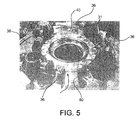
- centering jaws 36 opposite two by two (visible to the figure 5 ) between the fingers 20 and can be controlled by a radial movement in the mandrel 11 to move closer to each other and grip the neck 5 of the jar 1 by exerting a centering. They are therefore provided with a V-shaped footprint 37 in which part of the periphery of the neck 5 rests.
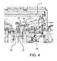
- the mandrel 11 is mounted on a turning machine 24 shown in FIG. figure 4 , by taking reliefs 23 which have not been completely represented.
- the turning machine 24 essentially comprises a frame 25, a motor 26 and a horizontal axis 27 rotating in the frame 25 under the effect of the motor 26.
- the horizontal axis 27 oscillates between a position where the mandrel 11 overhangs a well 28 of arrival jars 1 and is in the position shown in the figure 2 , with the docking face 22 below and a position where the mandrel 11 has tilted by almost a half-turn, the jar 1 is on it and its contents can then flow into a hopper 29 to which the mandrel 11 has mated, through a recess 33 formed through the mandrel 11 and on which is bottled the neck 4.
- the flow is not easy to accomplish, as already mentioned.
- the bottom (not shown) of the well 28 is occupied by a transport conveyor of the jars 1, and that an elevator 30 can convey the jars 1 and lift them in the well 28 towards the turning machine 24.
- the mandrel 11 is carrying vibration generators 31, here sixteen in number and distributed in an exciter plate 34 occupying at least half of its range according to the figures 2 and 5 .
- These are piezoelectric vibration generators which have the advantage of having a small footprint and can thus be placed without difficulty on a mandrel 11 of small dimensions.
- the docking face 22 is the bottom of the plate 34, which rests on the neck 5 of the jar 1 seized thereby establishing the seal.
- the vibrations are therefore communicated to vibration generators 31 at the neck 5 of the jar 1 by a direct contact, the vibration generators 31 flush with the docking face 22. It is advantageous if they have a sufficient intensity, which explains the use of a large number of vibration generators 31. They are operated alternately in groups (for example two groups of eight in one embodiment particular). These control means, two in number too, are subject to the fixed part 12 and have the reference 40.
Landscapes
- Engineering & Computer Science (AREA)
- Physics & Mathematics (AREA)
- Mechanical Engineering (AREA)
- High Energy & Nuclear Physics (AREA)
- Plasma & Fusion (AREA)
- General Engineering & Computer Science (AREA)
- Manufacturing & Machinery (AREA)
- Crushing And Grinding (AREA)
- Basic Packing Technique (AREA)
- Furnace Charging Or Discharging (AREA)
- Supplying Of Containers To The Packaging Station (AREA)
- Container Filling Or Packaging Operations (AREA)
- Eyeglasses (AREA)
- Application Of Or Painting With Fluid Materials (AREA)
- Apparatuses For Generation Of Mechanical Vibrations (AREA)
Description
- Le sujet de cette invention est un dispositif ainsi qu'un procédé de vidage de jarres par retournement, selon les préambules des revendications 1 et 6 respectivement. Un tel dispositif ainsi qu'un tel procédé sont décrits par le document
US A 4 569 623 . - Cette invention a été conçue pour une chaîne de production de combustibles nucléaires, mais elle pourra aussi trouver emploi dans d'autres applications quand des conditions analogues seront réunies, notamment pour vider des récipients contenant des poudres à écoulement difficile.
- Les poudres dont il est question dans l'application d'abord envisagée sont issues de pastilles de combustibles nucléaires qui ont été rebutées puis broyées et doivent resservir à la fabrication de nouvelles pastilles. Cette poudre appelée chamotte possède la particularité de taluter et de coller aux parois des récipients à usage d'entreposage et de transfert appelés jarres.
- La
figure 1 représente une jarre 1 de ce genre. Elle comprend un corps principal 2 cylindrique, un corps supérieur 3 conique et, au sommet, un goulot 4 finissant sur un col 5. La jarre 1 peut être close par un bouchon 6 qui est cependant retiré avant qu'elle n'arrive au dispositif de l'invention. Le centre du corps principal 2 est évidé pour constituer un puits de soufflage 7 (appelé ainsi parce qu'il est le siège d'une ventilation extérieure au stockage de la jarre 1 afin de favoriser son refroidissement) dont la portée s'étend jusque dans le corps supérieur 3 ; et le volume annulaire inclus entre le corps principal 2 et le puits de soufflage 7 porte un radiateur 9 en forme de nervure verticale et circulaire, destiné aussi à l'évacuation de la chaleur produite naturellement par le combustible emplissant la jarre 1. Le puits de soufflage 7 et le radiateur 9 sont tous deux unis au reste de la jarre 1 par le fond 8 du corps principal 2. On remarque enfin un bandage 10 formant une surépaisseur sur une partie de la hauteur du corps supérieur 3. - Quand, le bouchon 6 retiré, la jarre 1 est retournée, c'est sur le bandage 10 qu'on applique des chocs d'après le procédé connu afin de faire couler la poudre hors de la jarre. On utilise un percuteur à électro-aimant. Les résultats ne sont pourtant pas suffisants en raison du caractère collant de la poudre, et c'est pourquoi il est arrivé qu'on cherchât à compléter le vidage de la jarre 1 en appliquant à la main des coups de maillet sur différentes parties de sa surface. Les résultats n'étaient encore pas satisfaisants, même avec des chocs assez forts pour bosseler la jarre 1. Il faut admettre que la conicité forte du corps supérieur 3 et la présence des parois intérieures délimitant le puits d'évacuation de chaleur 7 et formant le radiateur 9 contribuent fortement au collage de la poudre.
- On cherche à éliminer cet inconvénient de mauvais vidage avec l'invention ; elle concerne d'abord un dispositif de vidage de jarres par retournement, selon la revendication 1. L'application de vibrations s'est révélée plus efficace que l'application de chocs bien que l'application d'énergie fût plus faible et dût se faire par les endroits où la couronne avait saisi la jarre, à l'extrémité supérieure et près du goulot, loin de ceux, au fond de la jarre, où la poudre séjourne et adhère.
- D'après certains détails de réalisation avantageux, les générateurs de vibrations sont situés sur les portions de mise en contact avec le goulot et sont en contact direct avec le goulot ; ils sont situés dans une plaque circulaire d'appui sur une face plane d'extrémité du col de la jarre située à une portion extrême du goulot ; et ils sont répartis sur une circonférence de la plaque circulaire occupant au moins une moitié de la circonférence.
- Un autre aspect de l'invention est un procédé de vidage de jarres , par retournement, selon la revendication 6.
- Une raison de l'efficacité meilleure de l'invention tient probablement à la possibilité d'exciter sur une plage large de fréquences de vibrations, éventuellement par un balayage de fréquences, de façon à éveiller un plus grand nombre de modes propres.
- L'invention sera maintenant décrite en liaison aux figures suivantes :
- la
figure 1 , déjà décrite, représente une jarre et son bouchon, - la
figure 2 illustre le mandrin d'accostage de la jarre en coupe diamétrale, - la
figure 3 illustre la couronne en vue partielle en direction de l'axe, - la
figure 4 illustre en partie le dispositif de retournement et de vidage, - et la
figure 5 représente la disposition des générateurs de vibrations. - L'appareil utilisé pour accoster, tenir et retourner les jarres 1 est représenté surtout aux
figures 2 et 3 . Il s'agit d'un mandrin 11 en forme générale de couronne. Le mandrin 11 comprend une partie fixe 12 et une partie mobile 13 circulaires, coaxiales. La partie mobile 13 est tournée par rapport à la partie fixe 12 par un pignon 14 entraîné lui-même par un moteur 15 fixé au sommet de la partie fixe 12. Le pignon 14 engrène pour cela avec un secteur denté 16 vissé sur la partie mobile 13. La course angulaire de la partie mobile 13 est limitée par deux butées 17 sur lesquelles le secteur denté 16 bute et qui sont montées sur la partie fixe 12. La partie mobile 13 est une couronne interne de roulement dentée à sa face interne et qui engrène avec quatre pignons 18 répartis sur un carré dans la couronne. La partie fixe 12 comprend une couronne externe de roulement 38, associée à la partie mobile 13 par une couche de billes 39. Les couronnes de roulement sont établies sur une portion principale 40 de la partie fixe 12. Les pignons 18, tournés par la partie mobile 13 à l'actionnement du moteur 15, font eux-mêmes tourner autant d'axes 19 montés dans la partie fixe 12 et qui leur sont coaxiaux, et qui portent des doigts 20 de verrouillage s'étendant radialement avec une inclinaison par rapport aux axes 19. Les doigts 20 peuvent passer sous le col 5 de la jarre 1 quand elle est placée sous le mandrin 11, et des galets 21 qui sont installés à leur extrémité libre roulent à la surface inférieure du col 5 et le pressent contre une face d'accostage 22 au fond de la couronne. Un mouvement inverse du mécanisme écarte les doigts 20 les uns des autres et permet de retirer la jarre 1. - De plus, il existe quatre mors de centrage 36 opposés deux à deux (visibles à la
figure 5 ) entre les doigts 20 et pouvant être commandés d'un mouvement radial dans le mandrin 11 pour se rapprocher l'un de l'autre et enserrer le col 5 de la jarre 1 en exerçant un centrage. Ils sont pour cela munis d'une empreinte en vé 37 dans laquelle une partie de la périphérie du col 5 repose. - Le mandrin 11 est monté sur une machine de retournement 24 représentée à la
figure 4 , par des reliefs de prise 23 qui n'ont pas été représentés complètement. La machine de retournement 24 comprend essentiellement un bâti 25, un moteur 26 et un axe horizontal 27 tournant dans le bâti 25 sous l'effet du moteur 26. - L'axe horizontal 27 oscille entre une position où le mandrin 11 surplombe un puits 28 d'arrivée des jarres 1 et se trouve dans la position représentée à la
figure 2 , avec la face d'accostage 22 au dessous et une position où le mandrin 11 a basculé de près d'un demi-tour, la jarre 1 se trouve sur elle et son contenu peut alors s'écouler dans une trémie 29 à laquelle le mandrin 11 s'est accolé, en traversant un évidement 33 ménagé à travers le mandrin 11 et sur lequel est abouché le goulot 4. Toutefois, l'écoulement n'est pas facile à accomplir, comme on l'a déjà mentionné. - Par souci d'être complet, on signale que le fond (non représenté) du puits 28 est occupé par un convoyeur de transport des jarres 1, et qu'un élévateur 30 peut convoyer les jarres 1 et les soulever dans le puits 28 vers la machine de retournement 24.
- Conformément à l'invention, le mandrin 11 est porteur de générateurs de vibrations 31, ici au nombre de seize et répartis dans une plaque excitatrice 34 en occupant au moins sa moitié de son étendue d'après les
figures 2 et5 . Ce sont des générateurs de vibrations piézoélectriques qui ont l'avantage d'avoir un encombrement faible et de pouvoir ainsi être placés sans difficulté sur un mandrin 11 de petites dimensions. La face d'accostage 22 est le fond de la plaque 34, qui repose sur le col 5 de la jarre 1 saisie en établissant ainsi l'étanchéité. Les vibrations sont donc communiquées à des générateurs de vibrations 31 au col 5 de la jarre 1 par un contact direct, les générateurs de vibrations 31 affleurant à la face d'accostage 22. Il est avantageux qu'elles aient une intensité suffisante, ce qui explique l'emploi d'un nombre important des générateurs de vibrations 31. Ils sont mis en service alternativement par groupes (par exemple deux groupes de huit dans une réalisation particulière). Ces moyens de commande, au nombre de deux aussi, sont assujettis à la partie fixe 12 et portent la référence 40. - L'expérience et l'analyse modale des jarres 1 ont montré que le col 5 était l'endroit d'application des vibrations où la jarre 1 vibrait le mieux, alors que les vibrations et les chocs infligés ailleurs, et notamment sur le bandage 10, avaient un effet bien inférieur. De plus, les générateurs de vibrations 31 permettent d'effectuer des balayages en fréquence qui viennent à exciter les parois de la jarre 1 selon des modes propres bien différents et qui permettent donc beaucoup mieux de décoller partout la poudre en faisant de chaque parcelle la jarre 1 tour à tour un ventre des vibrations. On cherche à exciter aux modes de résonance donnant un fort coefficient d'amplification entre la zone sollicitée où les générateurs de vibrations 31 sont placés, ici le col 5, et les endroits où se colle la poudre, ici près du fond de la jarre 1. On a trouvé, pour un cas particulier d'un modèle de jarres nommé J60, que de balayer autour de 326 Hertz et de 726 Hertz pendant plusieurs minutes, puis de recommencer dans l'autre sens, donnait de très bons résultats ; ces fréquences correspondent aux deux premiers modes propres de vibrations longitudinales des jarres 1 si bien que les vibrations se répandent sur toute leur hauteur et atteignent toutes les portions où la poudre adhère.
Claims (11)
- Dispositif de vidage de jarres contenant des poudres à l'écoulement difficile, par retournement, comprenant un mandrin (11) monté sur une machine de retournement (24) laquelle comprend essentiellement un bâti (25), un moteur (26) et un axe horizontal (27) tournant dans le bâti (25) sous l'effet du moteur (26), le mandrin (11) venant entourer un goulot (4) de la jarre (1) et comprenant des portions de mise en contact du goulot (4) de la jarre (1), caractérisé en ce que le mandrin comprend des générateurs de vibrations (31).
- Dispositif de vidage de jarres selon la revendication 1, caractérisé en ce que les générateurs de vibrations sont situés sur les portions de mise en contact du goulot et sont en contact direct avec le goulot.
- Dispositif de vidage de jarres selon la revendication 2, caractérisé en ce que les générateurs de vibrations (31) sont situés dans une plaque circulaire (34) d'appui sur une face plane d'extrémité d'un col (5) de la jarre (1) à une portion extrême du goulot (4).
- Dispositif de vidage de jarres selon la revendication 3, caractérisé en ce que les générateurs de vibrations (31) sont répartis sur une circonférence de la plaque circulaire (34) en occupant au moins une moitié de la circonférence.
- Dispositif de vidage de jarres selon l'une quelconque des revendications précédentes, caractérisé en ce que les générateurs de vibrations sont piézoélectriques.
- Procédé de vidage de jarres, par retournement selon la revendication 1, comprenant une étape de saisie d'un goulot de la jarre par un mandrin d'accostage, une étape de retournement de la jarre en faisant basculer le mandrin, et une étape de mise en vibration de la jarre, caractérisé en ce que la mise en vibration de la jarre est assurée par le mandrin.
- Procédé de vidage de jarres selon la revendication 6, caractérisé en ce que la mise en vibration de la jarre est effectuée par un balayage d'au moins une plage de fréquences de vibrations.
- Procédé de vidage de jarres selon la revendication 7, caractérisé en ce qu'il comprend deux plages de fréquences de vibrations s'étendant autour de 326 Hz et 726 Hz.
- Procédé de vidage de jarres selon la revendication 7 ou 8, caractérisé en ce que chaque plage de fréquences de vibrations est placée autour d'un mode propre de vibration longitudinale de la jarre (1).
- Procédé de vidage de jarres selon l'une quelconque des revendications 6 à 9, caractérisé en ce que la jarre est mise en vibration par un goulot (4).
- Procédé de vidage de jarres selon l'une quelconque des revendications 6 à 10, caractérisé en ce que les vibrations sont d'origine piézoélectrique.
Applications Claiming Priority (2)
| Application Number | Priority Date | Filing Date | Title |
|---|---|---|---|
| FR0752611A FR2911128B1 (fr) | 2007-01-10 | 2007-01-10 | Dispositif et procede de vidage de jarres |
| PCT/EP2008/050113 WO2008084032A1 (fr) | 2007-01-10 | 2008-01-08 | Dispositif et procede de vidage de jarres |
Publications (2)
| Publication Number | Publication Date |
|---|---|
| EP2099699A1 EP2099699A1 (fr) | 2009-09-16 |
| EP2099699B1 true EP2099699B1 (fr) | 2011-03-30 |
Family
ID=38420588
Family Applications (1)
| Application Number | Title | Priority Date | Filing Date |
|---|---|---|---|
| EP08701288A Active EP2099699B1 (fr) | 2007-01-10 | 2008-01-08 | Dispositif et procede de vidage de jarres |
Country Status (10)
| Country | Link |
|---|---|
| US (1) | US20100038377A1 (fr) |
| EP (1) | EP2099699B1 (fr) |
| JP (1) | JP2010515629A (fr) |
| CN (1) | CN101610959B (fr) |
| AT (1) | ATE503708T1 (fr) |
| DE (1) | DE602008005840D1 (fr) |
| FR (1) | FR2911128B1 (fr) |
| RU (1) | RU2464215C2 (fr) |
| WO (1) | WO2008084032A1 (fr) |
| ZA (1) | ZA200904348B (fr) |
Families Citing this family (4)
| Publication number | Priority date | Publication date | Assignee | Title |
|---|---|---|---|---|
| RU2458837C1 (ru) * | 2011-05-19 | 2012-08-20 | Константин Владимирович Гайдуков | Бункерное устройство |
| FR2984790B1 (fr) | 2011-12-22 | 2014-02-21 | Areva Nc | Dispositif de manipulation d'objets en boites a gants |
| FR2990933B1 (fr) | 2012-05-22 | 2014-07-04 | Areva Nc | Dispositif de stockage indexe en position |
| EP3453459A1 (fr) | 2017-09-06 | 2019-03-13 | Siemens Aktiengesellschaft | Procédé de fonctionnement d'une installation, installation et produit-programme informatique |
Family Cites Families (25)
| Publication number | Priority date | Publication date | Assignee | Title |
|---|---|---|---|---|
| US4069930A (en) * | 1976-04-12 | 1978-01-24 | Philip Morris Incorporated | Apparatus for handling rod-shaped articles |
| US4472091A (en) * | 1983-04-25 | 1984-09-18 | Pennwalt Corporation | Dry powder metering apparatus |
| US4569623A (en) * | 1984-12-06 | 1986-02-11 | The United States Of America As Represented By The United States Department Of Energy | Dump assembly |
| JPS6264768A (ja) * | 1985-09-11 | 1987-03-23 | 加藤 真彦 | 油タンク |
| JPS62259983A (ja) * | 1986-05-06 | 1987-11-12 | 日清製粉株式会社 | フレキシブルコンテナの充填出荷方法 |
| JPH01240483A (ja) * | 1988-03-14 | 1989-09-26 | Agency Of Ind Science & Technol | 微粉末微量取出装置 |
| US4836417A (en) * | 1988-08-29 | 1989-06-06 | Agency Of Industrial Science And Technology | Apparatus for continuous supply of fine powder, viscous fluid or the like at a constant rate |
| DE4023163C2 (de) * | 1990-07-20 | 1998-07-09 | Siemens Ag | Trockenstation sowie Einrichtung zur Behandlung von flüssigen radioaktiven Abfällen |
| JP3391490B2 (ja) * | 1992-12-18 | 2003-03-31 | 株式会社湯山製作所 | 粉体搬送装置 |
| US5472117A (en) * | 1993-10-05 | 1995-12-05 | Ctb, Inc. | Flow facilitation and control system and related method |
| JP3437332B2 (ja) * | 1995-07-10 | 2003-08-18 | キヤノン株式会社 | 粉体供給用容器と該粉体供給用容器の製造方法及び粉体供給方法 |
| US5702225A (en) * | 1996-06-05 | 1997-12-30 | Amrep, Inc. | Boomless automated side loader for refuse collection vehicle having lift arm with non-extendable upper end |
| JPH1017076A (ja) * | 1996-07-03 | 1998-01-20 | Minolta Co Ltd | 粉体収容タンク |
| FR2751311B1 (fr) * | 1996-07-22 | 1998-09-25 | Technilab | Dispositif de secouage de conteneur rigide et procede de vidage |
| JP3577177B2 (ja) * | 1996-10-11 | 2004-10-13 | 愛三工業株式会社 | アクチュエータの制御装置及び粉体フィーダ |
| US5960990A (en) * | 1997-09-06 | 1999-10-05 | Radosevich; Paul T. | Product discharge activator and method of use |
| GB2329178B (en) * | 1997-09-12 | 2001-07-25 | Process Link Ltd | Apparatus for discharging particulate material |
| JP3678900B2 (ja) * | 1998-01-29 | 2005-08-03 | 電気化学工業株式会社 | 粉粒体の排出方法、排出装置および供給装置 |
| JP2000255789A (ja) * | 1999-03-04 | 2000-09-19 | Nippon Flour Mills Co Ltd | 振動ホッパ |
| US20020191869A1 (en) * | 1999-12-23 | 2002-12-19 | Stewart Gregory Roy | Bag assembly |
| BE1013367A3 (nl) * | 2000-03-31 | 2001-12-04 | J Tec Service Nv | Doseerinrichting. |
| US20050269364A1 (en) * | 2004-04-30 | 2005-12-08 | Gibson Rayce D | Inflatable seal for bin discharge system |
| JP4585412B2 (ja) * | 2004-09-16 | 2010-11-24 | 株式会社日清製粉グループ本社 | 振動式粉粒体排出装置 |
| CN1757582A (zh) * | 2005-10-21 | 2006-04-12 | 长春吉大科学仪器设备有限公司 | 新型微振动送料装置 |
| CN1757579A (zh) * | 2005-10-21 | 2006-04-12 | 长春吉大科学仪器设备有限公司 | 新型悬挂式压电振动料斗 |
-
2007
- 2007-01-10 FR FR0752611A patent/FR2911128B1/fr not_active Expired - Fee Related
-
2008
- 2008-01-08 CN CN2008800019369A patent/CN101610959B/zh active Active
- 2008-01-08 DE DE602008005840T patent/DE602008005840D1/de active Active
- 2008-01-08 RU RU2009130361/12A patent/RU2464215C2/ru not_active IP Right Cessation
- 2008-01-08 WO PCT/EP2008/050113 patent/WO2008084032A1/fr not_active Ceased
- 2008-01-08 JP JP2009545164A patent/JP2010515629A/ja active Pending
- 2008-01-08 US US12/522,906 patent/US20100038377A1/en not_active Abandoned
- 2008-01-08 EP EP08701288A patent/EP2099699B1/fr active Active
- 2008-01-08 AT AT08701288T patent/ATE503708T1/de not_active IP Right Cessation
-
2009
- 2009-06-22 ZA ZA200904348A patent/ZA200904348B/xx unknown
Also Published As
| Publication number | Publication date |
|---|---|
| DE602008005840D1 (de) | 2011-05-12 |
| WO2008084032A1 (fr) | 2008-07-17 |
| JP2010515629A (ja) | 2010-05-13 |
| ZA200904348B (en) | 2010-04-28 |
| FR2911128B1 (fr) | 2009-04-03 |
| RU2464215C2 (ru) | 2012-10-20 |
| CN101610959B (zh) | 2012-05-23 |
| EP2099699A1 (fr) | 2009-09-16 |
| FR2911128A1 (fr) | 2008-07-11 |
| US20100038377A1 (en) | 2010-02-18 |
| ATE503708T1 (de) | 2011-04-15 |
| RU2009130361A (ru) | 2011-02-20 |
| CN101610959A (zh) | 2009-12-23 |
Similar Documents
| Publication | Publication Date | Title |
|---|---|---|
| EP0553190B1 (fr) | Godet melangeur pour un malaxeur centrifuge planetaire, et malaxeur recevant de tels godets | |
| EP2821146B1 (fr) | Dispositif et procédé de secouage et de centrifugation. | |
| WO2008084032A1 (fr) | Dispositif et procede de vidage de jarres | |
| WO2010007273A1 (fr) | Mélange dans un conteneur d'un contenu ayant un composant de base et un composant à mélanger | |
| EP3781490B1 (fr) | Dispositif de protection contre les chocs apte à équiper une bouteille et récipient antichocs | |
| WO1992013663A1 (fr) | Procede et dispositifs de debourrage de noyaux de coulee de pieces de fonderie | |
| FR2611469A1 (fr) | Tasse a cafe ou pour boissons similaires, en matiere synthetique thermoplastique | |
| EP2522598B1 (fr) | Dispositif de déformation de la paroi périphérique de gobelets carton empilables | |
| CH391577A (fr) | Procédé de transfert de corps creux et dispositif pour sa mise en oeuvre | |
| FR2802176A1 (fr) | Procede et dispositif pour conditionner un solide, notamment alimentaire, dans un recipient tel que flacon | |
| EP2204322B1 (fr) | Dispositif et procédé de remplissage de pots alimentaires | |
| FR2899067A1 (fr) | Casseuse a noix | |
| FR2669012A1 (fr) | Systeme d'extraction des matieres granuleuses ou pulverulentes contenues dans un silo. | |
| WO2021001490A1 (fr) | Dispositif de fourniture d'elements de bouchage tries | |
| FR2998466A1 (fr) | Appareil de traitement d'aliments a outil equilibre | |
| EP0425323A1 (fr) | Procédé et dispositif pour l'orientation axiale et unidirectionnelle de pièces en forme de douille avec une paroi d'extrémitÀ© transversale | |
| FR3068572A1 (fr) | Casse-noix ameliore. | |
| FR2513230A1 (fr) | Appareil pour l'evacuation de matieres en vrac | |
| WO2012168269A1 (fr) | Bouteille a coque | |
| EP4403479A1 (fr) | Dispositif de retournement de fond de récipient | |
| FR2663312A1 (fr) | Procede et installation de chargement des conteneurs de remuage de bouteilles de vin de champagne. | |
| WO1998010892A1 (fr) | Dispositif de traitement de pieces par grenaillage, plus particulierement au moyen de billes d'acier mises en mouvement par un champ ultrasonore | |
| FR2751311A1 (fr) | Dispositif de secouage de conteneur rigide et procede de vidage | |
| CH715670B1 (fr) | Module de séparation de pièces mécaniques agglomérées. | |
| FR2716161A1 (fr) | Bouteille axialement écrasable en matière plastique et moule de fabrication de cette bouteille. |
Legal Events
| Date | Code | Title | Description |
|---|---|---|---|
| PUAI | Public reference made under article 153(3) epc to a published international application that has entered the european phase |
Free format text: ORIGINAL CODE: 0009012 |
|
| 17P | Request for examination filed |
Effective date: 20090703 |
|
| AK | Designated contracting states |
Kind code of ref document: A1 Designated state(s): AT BE BG CH CY CZ DE DK EE ES FI FR GB GR HR HU IE IS IT LI LT LU LV MC MT NL NO PL PT RO SE SI SK TR |
|
| DAX | Request for extension of the european patent (deleted) | ||
| GRAP | Despatch of communication of intention to grant a patent |
Free format text: ORIGINAL CODE: EPIDOSNIGR1 |
|
| GRAS | Grant fee paid |
Free format text: ORIGINAL CODE: EPIDOSNIGR3 |
|
| GRAA | (expected) grant |
Free format text: ORIGINAL CODE: 0009210 |
|
| AK | Designated contracting states |
Kind code of ref document: B1 Designated state(s): AT BE BG CH CY CZ DE DK EE ES FI FR GB GR HR HU IE IS IT LI LT LU LV MC MT NL NO PL PT RO SE SI SK TR |
|
| REG | Reference to a national code |
Ref country code: GB Ref legal event code: FG4D Free format text: NOT ENGLISH |
|
| REG | Reference to a national code |
Ref country code: CH Ref legal event code: EP |
|
| REG | Reference to a national code |
Ref country code: IE Ref legal event code: FG4D |
|
| REF | Corresponds to: |
Ref document number: 602008005840 Country of ref document: DE Date of ref document: 20110512 Kind code of ref document: P |
|
| REG | Reference to a national code |
Ref country code: DE Ref legal event code: R096 Ref document number: 602008005840 Country of ref document: DE Effective date: 20110512 |
|
| REG | Reference to a national code |
Ref country code: NL Ref legal event code: VDEP Effective date: 20110330 |
|
| REG | Reference to a national code |
Ref country code: SE Ref legal event code: TRGR |
|
| PG25 | Lapsed in a contracting state [announced via postgrant information from national office to epo] |
Ref country code: LT Free format text: LAPSE BECAUSE OF FAILURE TO SUBMIT A TRANSLATION OF THE DESCRIPTION OR TO PAY THE FEE WITHIN THE PRESCRIBED TIME-LIMIT Effective date: 20110330 Ref country code: HR Free format text: LAPSE BECAUSE OF FAILURE TO SUBMIT A TRANSLATION OF THE DESCRIPTION OR TO PAY THE FEE WITHIN THE PRESCRIBED TIME-LIMIT Effective date: 20110330 Ref country code: GR Free format text: LAPSE BECAUSE OF FAILURE TO SUBMIT A TRANSLATION OF THE DESCRIPTION OR TO PAY THE FEE WITHIN THE PRESCRIBED TIME-LIMIT Effective date: 20110701 Ref country code: LV Free format text: LAPSE BECAUSE OF FAILURE TO SUBMIT A TRANSLATION OF THE DESCRIPTION OR TO PAY THE FEE WITHIN THE PRESCRIBED TIME-LIMIT Effective date: 20110330 |
|
| LTIE | Lt: invalidation of european patent or patent extension |
Effective date: 20110330 |
|
| PG25 | Lapsed in a contracting state [announced via postgrant information from national office to epo] |
Ref country code: AT Free format text: LAPSE BECAUSE OF FAILURE TO SUBMIT A TRANSLATION OF THE DESCRIPTION OR TO PAY THE FEE WITHIN THE PRESCRIBED TIME-LIMIT Effective date: 20110330 Ref country code: SI Free format text: LAPSE BECAUSE OF FAILURE TO SUBMIT A TRANSLATION OF THE DESCRIPTION OR TO PAY THE FEE WITHIN THE PRESCRIBED TIME-LIMIT Effective date: 20110330 Ref country code: CY Free format text: LAPSE BECAUSE OF FAILURE TO SUBMIT A TRANSLATION OF THE DESCRIPTION OR TO PAY THE FEE WITHIN THE PRESCRIBED TIME-LIMIT Effective date: 20110330 Ref country code: FI Free format text: LAPSE BECAUSE OF FAILURE TO SUBMIT A TRANSLATION OF THE DESCRIPTION OR TO PAY THE FEE WITHIN THE PRESCRIBED TIME-LIMIT Effective date: 20110330 Ref country code: NO Free format text: LAPSE BECAUSE OF FAILURE TO SUBMIT A TRANSLATION OF THE DESCRIPTION OR TO PAY THE FEE WITHIN THE PRESCRIBED TIME-LIMIT Effective date: 20110630 |
|
| REG | Reference to a national code |
Ref country code: IE Ref legal event code: FD4D |
|
| PG25 | Lapsed in a contracting state [announced via postgrant information from national office to epo] |
Ref country code: EE Free format text: LAPSE BECAUSE OF FAILURE TO SUBMIT A TRANSLATION OF THE DESCRIPTION OR TO PAY THE FEE WITHIN THE PRESCRIBED TIME-LIMIT Effective date: 20110330 Ref country code: PT Free format text: LAPSE BECAUSE OF FAILURE TO SUBMIT A TRANSLATION OF THE DESCRIPTION OR TO PAY THE FEE WITHIN THE PRESCRIBED TIME-LIMIT Effective date: 20110801 |
|
| PG25 | Lapsed in a contracting state [announced via postgrant information from national office to epo] |
Ref country code: CZ Free format text: LAPSE BECAUSE OF FAILURE TO SUBMIT A TRANSLATION OF THE DESCRIPTION OR TO PAY THE FEE WITHIN THE PRESCRIBED TIME-LIMIT Effective date: 20110330 Ref country code: RO Free format text: LAPSE BECAUSE OF FAILURE TO SUBMIT A TRANSLATION OF THE DESCRIPTION OR TO PAY THE FEE WITHIN THE PRESCRIBED TIME-LIMIT Effective date: 20110330 Ref country code: SK Free format text: LAPSE BECAUSE OF FAILURE TO SUBMIT A TRANSLATION OF THE DESCRIPTION OR TO PAY THE FEE WITHIN THE PRESCRIBED TIME-LIMIT Effective date: 20110330 Ref country code: ES Free format text: LAPSE BECAUSE OF FAILURE TO SUBMIT A TRANSLATION OF THE DESCRIPTION OR TO PAY THE FEE WITHIN THE PRESCRIBED TIME-LIMIT Effective date: 20110711 Ref country code: IS Free format text: LAPSE BECAUSE OF FAILURE TO SUBMIT A TRANSLATION OF THE DESCRIPTION OR TO PAY THE FEE WITHIN THE PRESCRIBED TIME-LIMIT Effective date: 20110730 |
|
| PG25 | Lapsed in a contracting state [announced via postgrant information from national office to epo] |
Ref country code: NL Free format text: LAPSE BECAUSE OF FAILURE TO SUBMIT A TRANSLATION OF THE DESCRIPTION OR TO PAY THE FEE WITHIN THE PRESCRIBED TIME-LIMIT Effective date: 20110330 |
|
| PG25 | Lapsed in a contracting state [announced via postgrant information from national office to epo] |
Ref country code: IE Free format text: LAPSE BECAUSE OF FAILURE TO SUBMIT A TRANSLATION OF THE DESCRIPTION OR TO PAY THE FEE WITHIN THE PRESCRIBED TIME-LIMIT Effective date: 20110330 |
|
| PLBE | No opposition filed within time limit |
Free format text: ORIGINAL CODE: 0009261 |
|
| STAA | Information on the status of an ep patent application or granted ep patent |
Free format text: STATUS: NO OPPOSITION FILED WITHIN TIME LIMIT |
|
| PG25 | Lapsed in a contracting state [announced via postgrant information from national office to epo] |
Ref country code: PL Free format text: LAPSE BECAUSE OF FAILURE TO SUBMIT A TRANSLATION OF THE DESCRIPTION OR TO PAY THE FEE WITHIN THE PRESCRIBED TIME-LIMIT Effective date: 20110330 Ref country code: DK Free format text: LAPSE BECAUSE OF FAILURE TO SUBMIT A TRANSLATION OF THE DESCRIPTION OR TO PAY THE FEE WITHIN THE PRESCRIBED TIME-LIMIT Effective date: 20110330 |
|
| 26N | No opposition filed |
Effective date: 20120102 |
|
| REG | Reference to a national code |
Ref country code: DE Ref legal event code: R097 Ref document number: 602008005840 Country of ref document: DE Effective date: 20120102 |
|
| PG25 | Lapsed in a contracting state [announced via postgrant information from national office to epo] |
Ref country code: IT Free format text: LAPSE BECAUSE OF FAILURE TO SUBMIT A TRANSLATION OF THE DESCRIPTION OR TO PAY THE FEE WITHIN THE PRESCRIBED TIME-LIMIT Effective date: 20110330 |
|
| PG25 | Lapsed in a contracting state [announced via postgrant information from national office to epo] |
Ref country code: MC Free format text: LAPSE BECAUSE OF NON-PAYMENT OF DUE FEES Effective date: 20120131 |
|
| REG | Reference to a national code |
Ref country code: CH Ref legal event code: PL |
|
| PG25 | Lapsed in a contracting state [announced via postgrant information from national office to epo] |
Ref country code: CH Free format text: LAPSE BECAUSE OF NON-PAYMENT OF DUE FEES Effective date: 20120131 Ref country code: LI Free format text: LAPSE BECAUSE OF NON-PAYMENT OF DUE FEES Effective date: 20120131 |
|
| PGFP | Annual fee paid to national office [announced via postgrant information from national office to epo] |
Ref country code: DE Payment date: 20130110 Year of fee payment: 6 Ref country code: SE Payment date: 20130114 Year of fee payment: 6 |
|
| PGFP | Annual fee paid to national office [announced via postgrant information from national office to epo] |
Ref country code: BE Payment date: 20130130 Year of fee payment: 6 |
|
| PG25 | Lapsed in a contracting state [announced via postgrant information from national office to epo] |
Ref country code: BG Free format text: LAPSE BECAUSE OF FAILURE TO SUBMIT A TRANSLATION OF THE DESCRIPTION OR TO PAY THE FEE WITHIN THE PRESCRIBED TIME-LIMIT Effective date: 20110630 |
|
| PG25 | Lapsed in a contracting state [announced via postgrant information from national office to epo] |
Ref country code: MT Free format text: LAPSE BECAUSE OF FAILURE TO SUBMIT A TRANSLATION OF THE DESCRIPTION OR TO PAY THE FEE WITHIN THE PRESCRIBED TIME-LIMIT Effective date: 20110330 |
|
| PG25 | Lapsed in a contracting state [announced via postgrant information from national office to epo] |
Ref country code: TR Free format text: LAPSE BECAUSE OF FAILURE TO SUBMIT A TRANSLATION OF THE DESCRIPTION OR TO PAY THE FEE WITHIN THE PRESCRIBED TIME-LIMIT Effective date: 20110330 |
|
| PG25 | Lapsed in a contracting state [announced via postgrant information from national office to epo] |
Ref country code: LU Free format text: LAPSE BECAUSE OF NON-PAYMENT OF DUE FEES Effective date: 20120108 |
|
| BERE | Be: lapsed |
Owner name: AREVA NC Effective date: 20140131 |
|
| PG25 | Lapsed in a contracting state [announced via postgrant information from national office to epo] |
Ref country code: HU Free format text: LAPSE BECAUSE OF FAILURE TO SUBMIT A TRANSLATION OF THE DESCRIPTION OR TO PAY THE FEE WITHIN THE PRESCRIBED TIME-LIMIT Effective date: 20080108 |
|
| REG | Reference to a national code |
Ref country code: DE Ref legal event code: R119 Ref document number: 602008005840 Country of ref document: DE |
|
| REG | Reference to a national code |
Ref country code: SE Ref legal event code: EUG |
|
| REG | Reference to a national code |
Ref country code: DE Ref legal event code: R119 Ref document number: 602008005840 Country of ref document: DE Effective date: 20140801 |
|
| PG25 | Lapsed in a contracting state [announced via postgrant information from national office to epo] |
Ref country code: DE Free format text: LAPSE BECAUSE OF NON-PAYMENT OF DUE FEES Effective date: 20140801 |
|
| PG25 | Lapsed in a contracting state [announced via postgrant information from national office to epo] |
Ref country code: SE Free format text: LAPSE BECAUSE OF NON-PAYMENT OF DUE FEES Effective date: 20140109 |
|
| PG25 | Lapsed in a contracting state [announced via postgrant information from national office to epo] |
Ref country code: BE Free format text: LAPSE BECAUSE OF NON-PAYMENT OF DUE FEES Effective date: 20140131 |
|
| REG | Reference to a national code |
Ref country code: FR Ref legal event code: PLFP Year of fee payment: 9 |
|
| REG | Reference to a national code |
Ref country code: FR Ref legal event code: PLFP Year of fee payment: 10 |
|
| REG | Reference to a national code |
Ref country code: FR Ref legal event code: PLFP Year of fee payment: 11 |
|
| REG | Reference to a national code |
Ref country code: GB Ref legal event code: 732E Free format text: REGISTERED BETWEEN 20220217 AND 20220223 |
|
| PGFP | Annual fee paid to national office [announced via postgrant information from national office to epo] |
Ref country code: FR Payment date: 20250122 Year of fee payment: 18 |
|
| PGFP | Annual fee paid to national office [announced via postgrant information from national office to epo] |
Ref country code: GB Payment date: 20250122 Year of fee payment: 18 |