EP2100158B1 - Procédé d'obtention des courbes d'amplitude et de phase d'impulsions hf en vue d'une excitation spatiale sélective - Google Patents
Procédé d'obtention des courbes d'amplitude et de phase d'impulsions hf en vue d'une excitation spatiale sélective Download PDFInfo
- Publication number
- EP2100158B1 EP2100158B1 EP07846386.6A EP07846386A EP2100158B1 EP 2100158 B1 EP2100158 B1 EP 2100158B1 EP 07846386 A EP07846386 A EP 07846386A EP 2100158 B1 EP2100158 B1 EP 2100158B1
- Authority
- EP
- European Patent Office
- Prior art keywords
- basic
- basic patterns
- patterns
- pulse
- pulses
- Prior art date
- Legal status (The legal status is an assumption and is not a legal conclusion. Google has not performed a legal analysis and makes no representation as to the accuracy of the status listed.)
- Not-in-force
Links
Images




Classifications
-
- G—PHYSICS
- G01—MEASURING; TESTING
- G01R—MEASURING ELECTRIC VARIABLES; MEASURING MAGNETIC VARIABLES
- G01R33/00—Arrangements or instruments for measuring magnetic variables
- G01R33/20—Arrangements or instruments for measuring magnetic variables involving magnetic resonance
- G01R33/44—Arrangements or instruments for measuring magnetic variables involving magnetic resonance using nuclear magnetic resonance [NMR]
- G01R33/48—NMR imaging systems
- G01R33/58—Calibration of imaging systems, e.g. using test probes, Phantoms; Calibration objects or fiducial markers such as active or passive RF coils surrounding an MR active material
- G01R33/583—Calibration of signal excitation or detection systems, e.g. for optimal RF excitation power or frequency
-
- G—PHYSICS
- G01—MEASURING; TESTING
- G01R—MEASURING ELECTRIC VARIABLES; MEASURING MAGNETIC VARIABLES
- G01R33/00—Arrangements or instruments for measuring magnetic variables
- G01R33/20—Arrangements or instruments for measuring magnetic variables involving magnetic resonance
- G01R33/44—Arrangements or instruments for measuring magnetic variables involving magnetic resonance using nuclear magnetic resonance [NMR]
- G01R33/48—NMR imaging systems
- G01R33/483—NMR imaging systems with selection of signals or spectra from particular regions of the volume, e.g. in vivo spectroscopy
- G01R33/4833—NMR imaging systems with selection of signals or spectra from particular regions of the volume, e.g. in vivo spectroscopy using spatially selective excitation of the volume of interest, e.g. selecting non-orthogonal or inclined slices
- G01R33/4836—NMR imaging systems with selection of signals or spectra from particular regions of the volume, e.g. in vivo spectroscopy using spatially selective excitation of the volume of interest, e.g. selecting non-orthogonal or inclined slices using an RF pulse being spatially selective in more than one spatial dimension, e.g. a 2D pencil-beam excitation pulse
-
- G—PHYSICS
- G01—MEASURING; TESTING
- G01R—MEASURING ELECTRIC VARIABLES; MEASURING MAGNETIC VARIABLES
- G01R33/00—Arrangements or instruments for measuring magnetic variables
- G01R33/20—Arrangements or instruments for measuring magnetic variables involving magnetic resonance
- G01R33/44—Arrangements or instruments for measuring magnetic variables involving magnetic resonance using nuclear magnetic resonance [NMR]
- G01R33/48—NMR imaging systems
- G01R33/54—Signal processing systems, e.g. using pulse sequences ; Generation or control of pulse sequences; Operator console
- G01R33/56—Image enhancement or correction, e.g. subtraction or averaging techniques, e.g. improvement of signal-to-noise ratio and resolution
- G01R33/561—Image enhancement or correction, e.g. subtraction or averaging techniques, e.g. improvement of signal-to-noise ratio and resolution by reduction of the scanning time, i.e. fast acquiring systems, e.g. using echo-planar pulse sequences
- G01R33/5611—Parallel magnetic resonance imaging, e.g. sensitivity encoding [SENSE], simultaneous acquisition of spatial harmonics [SMASH], unaliasing by Fourier encoding of the overlaps using the temporal dimension [UNFOLD], k-t-broad-use linear acquisition speed-up technique [k-t-BLAST], k-t-SENSE
- G01R33/5612—Parallel RF transmission, i.e. RF pulse transmission using a plurality of independent transmission channels
-
- G—PHYSICS
- G01—MEASURING; TESTING
- G01R—MEASURING ELECTRIC VARIABLES; MEASURING MAGNETIC VARIABLES
- G01R33/00—Arrangements or instruments for measuring magnetic variables
- G01R33/20—Arrangements or instruments for measuring magnetic variables involving magnetic resonance
- G01R33/44—Arrangements or instruments for measuring magnetic variables involving magnetic resonance using nuclear magnetic resonance [NMR]
- G01R33/48—NMR imaging systems
- G01R33/54—Signal processing systems, e.g. using pulse sequences ; Generation or control of pulse sequences; Operator console
- G01R33/56—Image enhancement or correction, e.g. subtraction or averaging techniques, e.g. improvement of signal-to-noise ratio and resolution
- G01R33/561—Image enhancement or correction, e.g. subtraction or averaging techniques, e.g. improvement of signal-to-noise ratio and resolution by reduction of the scanning time, i.e. fast acquiring systems, e.g. using echo-planar pulse sequences
- G01R33/5611—Parallel magnetic resonance imaging, e.g. sensitivity encoding [SENSE], simultaneous acquisition of spatial harmonics [SMASH], unaliasing by Fourier encoding of the overlaps using the temporal dimension [UNFOLD], k-t-broad-use linear acquisition speed-up technique [k-t-BLAST], k-t-SENSE
-
- G—PHYSICS
- G01—MEASURING; TESTING
- G01R—MEASURING ELECTRIC VARIABLES; MEASURING MAGNETIC VARIABLES
- G01R33/00—Arrangements or instruments for measuring magnetic variables
- G01R33/20—Arrangements or instruments for measuring magnetic variables involving magnetic resonance
- G01R33/44—Arrangements or instruments for measuring magnetic variables involving magnetic resonance using nuclear magnetic resonance [NMR]
- G01R33/48—NMR imaging systems
- G01R33/58—Calibration of imaging systems, e.g. using test probes, Phantoms; Calibration objects or fiducial markers such as active or passive RF coils surrounding an MR active material
- G01R33/583—Calibration of signal excitation or detection systems, e.g. for optimal RF excitation power or frequency
- G01R33/586—Calibration of signal excitation or detection systems, e.g. for optimal RF excitation power or frequency for optimal flip angle of RF pulses
Definitions
- MR measuring system magnetic resonance measuring system
- Such a method is known for example from [6].
- Magnetic resonance imaging also known as magnetic resonance imaging (MRI)
- MRI Magnetic resonance imaging
- MRI Magnetic resonance imaging
- MRI Magnetic resonance imaging
- core spins contained in it are oriented with respect to the direction of the basic field, as a rule chosen as the z direction of a magnetically bonded coordinate system.
- MR examination by irradiation of electromagnetic RF pulses by means of one or more RF transmitting antennas, the thus oriented nuclear spins of the examination subject are excited to precession movements whose frequencies are proportional to the local magnetic field strengths.
- the precession movements of the nuclear spins are impressed by time-varying superpositions of gradient fields G x , G y and G z , which are generated with a gradient system, for all three spatial directions, a spatial coding, generally referred to as spatial encoding .
- This spatial coding is usually described by a scheme in a space conjugated to the spatial space via a Fourier transformation, the so-called k-space.
- the transversal component of the magnetization associated with the precessing nuclear spins induces voltage signals in one or more RF receiving antennas surrounding the examination subject.
- pulse sequences which contain specially selected sequences of RF pulses and gradient pulses
- temporally variable magnetic resonance signals are generated such that they can be converted into corresponding spatial images. This is done according to one of many well-known reconstruction techniques, after the RF signals have been recorded, amplified and digitized by means of an electronic receiving system and processed by means of an electronic computer system and stored in two- or three-dimensional data sets.
- the pulse sequence used contains a sequence of measurement sequences in which the gradient pulses are varied according to the selected localization method.
- An essential prerequisite for a true-to-life mapping of the nuclear spins of the examination object is that the technical imperfections of the MR measurement system are negligible or the deviations from the ideal behavior are known and can be corrected accordingly.
- Spatially selective excitation is a widely used technique in magnetic resonance imaging, which is used to spatially restrict the transverse magnetization generated during the excitation and / or to spatially vary its amplitude and phase in the excitation volume.
- slice selection the most common case of selective excitation, the excitation volume is reduced to a given layer.
- the multidimensional selective excitation in which the excitation volume is restricted in more than one direction or the excitation is modulated in more than one direction, has also produced numerous applications.
- the spatially selective excitation in the past has been carried out by means of a single RF transmitting antenna with a substantially homogeneous transmission field ( B 1 field) in combination with the gradient system.
- B 1 field substantially homogeneous transmission field
- a k-space trajectory adapted to the problem is chosen, i. the trajectory must adequately scan the k-space in all dimensions in which a spatial modulation of the transverse magnetization is to take place.
- a certain degree of undersampling may be permissible, which is limited upwards by the number of array elements and the nature of their spatial transmission profiles.
- a set of base pulses suitable for the k-space trajectory is selected, the term "pulse” in the following always being the entirety of all, possibly over several RF transmit channels and antennas, output in a specific time interval RF waves should denote.
- This set of basic pulses does not necessarily have to be complete, as explained in more detail below.
- these base pulses are then applied successively in combination with the selected k-space trajectory as excitation pulses from the RF transmitting antenna (s), the k-space trajectory, regardless of which base pulse is currently being used is played back completely in the same way, wherein the k-space trajectory during each base pulse at least from the time at which the pulse amplitude of the base pulse is different from zero for the first time, is completely identical.
- the k-space trajectory can also be used shortly before this time. However, this is only indicated if it can be ensured that the course of the k-space trajectory before this time does not have a significant effect on the trajectory after this point in time.
- the result of each of these MR experiments will be for a single base pulse each hereinafter referred to as a basic pattern.
- the basic patterns can be, for example, one-dimensional courses (eg slice profiles) or two- or three-dimensional magnetic resonance images.
- M xy (x) is the generated transverse magnetization pattern
- x is the location coordinate
- y is the gyromagnetic ratio of the spins studied
- M 0 is the equilibrium magnetization (the basic magnetic field is oriented in the z-direction)
- B 1 n is the complex RF waveform in Array element n
- S n is the spatial variation of the array element of array element n
- k is the k- space trajectory
- ⁇ off is the off- resonance frequency
- T 2 * is the effective transverse relaxation time
- T is the duration of the pulse M xy and B 1.
- n are complex Quantities whose real and imaginary parts describe the respective x or y component in the coordinate system rotating with the HF (vector values are in bold).
- the set of basic patterns obtained by the experiments described now serves as a basis for the calculation of the pulse required for a specific, desired excitation.
- the calculation is carried out in such a way that, in a fit method, the linear combination of the basic patterns which best corresponds to a given optimization criterion is determined.
- Such an optimization criterion may be the approximation of a given target pattern with the base patterns.
- the quality of the approximation can be defined by any cost function. It is also possible to choose a functional of the basic patterns as a cost function, via which the linear pattern of the basic patterns, which minimizes the functional, is indirectly defined as the target pattern.
- the desired pulse can be calculated as a corresponding linear combination of the basic pulses.
- a suitable linear or nonlinear optimization method must be selected. Such methods are known in the art.
- Such optimization can take many forms in practice.
- the simplest case would be to receive the MR signal with a single homogeneous RF receive antenna and to obtain a single MR image as a basic pattern to a single base pulse.
- the basic pattern is proportional to the transverse magnetization generated by the pulse (generally not to the flip angle, since the object may still have different spin densities), apart from relaxation effects.
- the optimization process determines the pulse which generates a pattern of the transverse magnetization which comes closest to the target pattern in terms of the cost function.
- the flip angle one must correct the basic patterns around the spin density in the object to obtain basic patterns that are proportional to the flip angle.
- a somewhat more complex case is when the signal is acquired with an array of m RF receive antennas. For each base pulse, a single antenna base pattern is received by each RF receive antenna. In this way, one obtains m sets of basic patterns to the one set of basic pulses. One can now combine the m sets of basic patterns before the pulse determination by linear combination of the single antenna base pattern into a single set of Bäsismustern, wherein in each of these linear combinations only Einzelantennen basic patterns of a particular base pulse are combined. Alternatively, in the course of the pulse determination, the identical linear combination can first be formed with the basic patterns within each sentence, and the m intermediate patterns thus obtained can subsequently be combined with an arbitrary, even non-linear combination to form a final pattern which is then to approximate a target pattern. Identical linear combination in this case means that the coefficient with which a certain base pattern is weighted is the same for all base patterns belonging to a specific base pulse, irrespective of their membership in a specific basic pattern.
- the method described offers the great advantage that interference effects which are such that the linear relationship between the pulse and the excitation pattern persists, such as the previously described imperfections of the MRI system, are taken into account intrinsically in the calculation method of the pulses and thus compensated for in a simple manner , It eliminates an elaborate and often difficult experimental conditions unstable measurement of parameter cards. Since the in situ calibration already takes place with the measurement sequence used later, additional disturbances which are usually to be expected in the event of changes in measurement conditions are avoided.
- the calibration step in the method described is more or less complicated.
- the exemplary embodiment is the correction of B 1 inhomogeneities in a slice-selective 2D MRI scan.
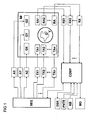
- Fig. 1 schematically an MR measuring system is shown, which is suitable for carrying out the method according to the invention.
- the system includes a main magnet M with which the examination volume is produced in a V substantially homogenous and static basic magnetic field.
- three sets of gradient coils GX, GY and GZ are introduced into the bore of the main magnet M , with which additional magnetic fields of controllable duration and intensity with constant gradients can be superimposed on the basic field.
- gradient amplifiers AX, AY and AZ which are controlled by a sequence control unit SEQ for the time-correct generation of gradient pulses, the gradient coils GX, GY, GZ are supplied with electric current for generating substantially linear gradient fields.
- RF transmission antennas TA1 to TA n which in their entirety are also referred to as transmit arrays consisting of n elements. They surround a subject O and are fed by several independent RF power transmitters TX1 to TX n . The RF pulses generated by these transmitters are determined by the sequence control unit SEQ and triggered in the correct time. RF pulses are n connected to the RF transmitting antennas TA1 to TA irradiated on the left in the examination volume V examination object O, see also Fig. 2 . and cause an excitation of nuclear spins there.
- the magnetic resonance signals produced thereby are also located within the gradient coils GX, GY, GZ with one or more RF receiving antennas RA1,..., RA m , which in their entirety are also referred to as receiving array, consisting of m elements, and the examination subject O, converted into electrical voltage signals, which are then fed to a corresponding number of receiving units RX1 to RX m .
- the antenna system can be designed and connected such that one or more of the RF transmission antennas TA1 to TAn are also used to receive the magnetic resonance signals. In such a case, in Fig.
- control computer system COMP serves to operate the entire MR measurement system and to initiate the execution of the pulse sequences by corresponding communication with the sequence control unit SEQ.
- the user-guided or automatic execution of programs for adjusting the measuring system properties and / or for generating magnetic resonance images also takes place on this control computer system COMP, such as the representation of the reconstructed images and the storage and management of the measurement and image data and the control programs.
- this computer system is at least with a processor, a random access memory, a computer keyboard KB, a pointing instrument PNTR, z. B. a computer mouse, a screen MON and an external digital storage unit DSK equipped.
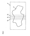
- FIG. 2 To clarify the imaging situation is in Fig. 2 within an examination volume V of the magnetic resonance system, an object O to be examined is shown.
- recordings in one or more layers S 1 , S 2 , S 3 , etc. are to be generated.
- the most homogeneous possible image profile is to be achieved by selective excitation.
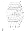
- Fig. 3 is a possible measurement sequence shown? The measurement process begins first with selecting a k-space trajectory adapted to the problem. Since, in the present example, a slice-selective excitation is to take place, wherein a correction of spatially slowly varying inhomogeneities of the B 1 field is to be carried out within the slice, a k-space trajectory, as proposed in US Pat Fig. 4 is shown (the trajectory is traversed as indicated by the ascending numbering 0 - 17). Trajectories of this type have been described by Saekho et al. [7] proposed.
- slice-selective subpulses are irradiated, preferably only while the z-direction oriented trajectories, also called spokes, are passed through (2-3, 4-5, 6-7, 8-9, 10-11 , 12-13, 14-16).
- These subpulses have identical shape but may vary in global amplitude and phase depending on the xy position on the trajectory.
- a slice selection is achieved in the z-direction, but at the same time a modulation of the transverse magnetization profile within the slice is achieved in the xy-plane.
- the k-space trajectory has seven spokes in the z-direction, during which the slice-selective subpulses can be applied.
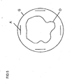
- excitation with a four-element transmit array is assumed, which of four independent transmission channels is driven.
- a scheme of this transmit array is in Fig. 5 displayed. It consists of a housing G, in which four array elements A are mounted, which are arranged in the present case rotationally symmetrical about the examination object O.
- the calculation of the RF pulse for a particular target pattern is to determine the amplitude and phase of the subpulse for all seven positions in k-space and all four array elements, which mathematically means finding 28 complex coefficients. Therefore, a set of 28 complex base pulses has been selected for calibration.
- each base pulse contains a subpulse with a unit amplitude and phase 0 exactly during one of the seven spokes in exactly one array element. But this is only one of basically infinite many possible basis sets.
- Basic pulses can also be selected in which non-vanishing subpulses occur at several k-space locations and in several array elements. It is only important that the base is linearly independent, ie no base pulse may be represented as a linear superposition of other base pulses.
- the measurements of the basic patterns are now carried out.
- the position of the layers must first be selected, which are then later used in the actual investigation.
- a standard gradient echo sequence was used in the present case, in which the excitation pulse was replaced by the described slice-selective pulse with B 1 correction.
- Data acquisition was done with the same array as sending.
- the data from the four receiving channels were combined in the image space as if the array had been operated as a birdcage receiving resonator with a phase difference of 90 ° between adjacent elements. So you get a complex image per calibration experiment and layer.
- the excitation flip angle in the base pulses is selected to be in Dependence of the repetition time of the gradient echo sequence is significantly smaller than the Ernst angle.
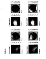
- Fig. 6b is exemplified, which basic patterns were generated in the present case by some selected basic pulses in an axial section plane of a water bottle. In the present example, without restriction of generality, only one layer was used.
- Fig. 6a First, four different basic pulses, which were played during the calibration experiments in the transmission array, are shown. In each diagram, a base pulse is shown in each case with its components played back in the respective array elements, wherein only the amplitude is always shown, since the phase was identical to zero in each case.
- Fig. 6b shows the magnitude images of the generated basic patterns - the intensity is normalized to the maximum of the four magnitude images - and the graphical representation of the phase curve (in radians).
- the target pattern is a homogeneous image with a phase progression that is constantly equal to 0.
- the amount of this picture is in Fig. 7 shown.
- a simple approximation criterion in this case is the smallest quadratic deviation of the linear combination of the basic patterns of the target pattern.
- Fig. 8 the amplitudes and phase curves of the thus determined pulse for the excitation of the target pattern are shown.
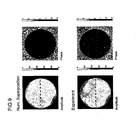
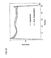
- Fig. 9 which pattern is obtained by superimposing the basic patterns numerically with the calculated coefficients. Furthermore, the result of an MR experiment using the determined pulse is shown, which shows a very good agreement with the numerical superposition. This is also going through again Fig. 10 affirms, in which two cuts out through the amount images Fig. 9 along the dashed lines drawn there are compared.
- the exemplary embodiment as described above leads primarily to a picture with a homogeneous amount if the received signals are combined as described. This is not necessarily identical to a homogeneous distribution of the generated transverse magnetization, since the signal reception or the combination of the received signals need not be spatially homogeneous, which is the case in the present example. So if you want to achieve a homogeneous distribution of the transverse magnetization, you would have to first correct the basic patterns with the spatial sensitivity profile of the reception mode used. If one wants to achieve even a homogeneous flip angle, one would additionally have to consider the spin density profile of the object to be imaged.
- a more direct way to achieve a homogeneous flip angle distribution in the present case is to record a map of the absolute value of its transmission field for each array element in addition to the basic pattern and the amount of the basic pattern with a different for each Sendearrayemia, but for all k-space -Positions of the same element identical spatial function to multiply, so that the belonging to the individual elements basic pattern in the k-space center in terms of amount equal to the respective transmit field map. If one applies the resulting pattern to a homogeneous pattern, one obtains a pulse which generates a homogeneous flip angle distribution.
- An important point in the method described in this invention is also the duration of the calibration step. As indicated above, it may not always be necessary to experimentally determine all basic patterns. Possibly. It is also possible to determine part of the basic patterns by means of symmetry considerations and known system properties from the others. In the present example, if one neglects effects of transverse relaxation, the basic patterns may be obtained as the product of a magnitude and phase distribution determined by the transmission profile of the array element and an additional spatially varying phase given by the position of the spoke in the k-space trajectory. but which is constant for all elements. Thus, it would be sufficient to experimentally determine those basic patterns which are among the basic pulses that apply a sub-pulse in the various array elements, respectively, during the central spoke.
- the method according to the invention makes it possible to determine RF pulses suitable for single-channel or multi-channel spatially selective excitation, whereby experimental imperfections are taken into account and intrinsically compensated.
- the searched pulses are determined by a linear combination corresponding to the linear combination of the basic patterns.
Landscapes
- Physics & Mathematics (AREA)
- General Physics & Mathematics (AREA)
- High Energy & Nuclear Physics (AREA)
- Condensed Matter Physics & Semiconductors (AREA)
- Nuclear Medicine, Radiotherapy & Molecular Imaging (AREA)
- Radiology & Medical Imaging (AREA)
- Engineering & Computer Science (AREA)
- Signal Processing (AREA)
- General Health & Medical Sciences (AREA)
- Health & Medical Sciences (AREA)
- Optics & Photonics (AREA)
- Spectroscopy & Molecular Physics (AREA)
- Magnetic Resonance Imaging Apparatus (AREA)
Claims (11)
- Procédé d'obtention des courbes d'amplitude et de phase d'impulsions à haute fréquence qui sont émises au moyen d'au moins une antenne émettrice HF d'un système de mesure par résonance magnétique pendant qu'elles parcourent une trajectoire prédéfinie dans l'espace k pour former un motif spatial n-dimensionnel avec n >= 1 de magnétisation transversale dans un objet dans le cadre d'une expérience de résonance magnétique à résolution spatiale,
caractérisé en ce
que dans une étape d'étalonnage- un jeu d'impulsions de base est prédéfini, une impulsion désignant la totalité des formes d'onde HF à reproduire pendant un processus d'émission dans la ou les antenne(s) émettrice(s) HF utilisée(s),- les impulsions de base du jeu sont émises individuellement et parcourent ce faisant chacune la trajectoire prédéfinie dans l'espace k, et par détection des signaux RM excités par l'injection de ces impulsions de base au moyen d'un dispositif de réception, au moins un jeu de motifs de base est produit, chaque motif de base étant proportionnel à la magnétisation transversale complexe produite par une impulsion de base au moins dans une zone à étudier de l'objet, la trajectoire dans l'espace k étant parcourue pendant chaque impulsion de base de manière complètement identique au moins à partir de l'instant auquel l'amplitude d'impulsion de l'impulsion de base est pour la première fois différente de zéro, et
qu'un motif cible prédéfini est approximé dans une étape de calcul- par une combinaison linéaire des motifs de base d'un seul jeu de motifs de base ou- par une combinaison mathématique de motifs intermédiaires qui sont produits par des combinaisons linéaires au sein de plusieurs jeux de motifs de base, les combinaisons linéaires au sein de chaque jeu de motifs de base étant effectuées de manière identique, une combinaison linéaire étant identique lorsque le coefficient avec lequel un motif de base défini est pondéré est le même pour tous les motifs de base appartenant à une impulsion de base définie, indépendamment de son appartenance à un jeu défini de motifs de base,et que les courbes d'amplitude et de phase à obtenir des impulsions à haute fréquence sont obtenues sous la forme d'une combinaison linéaire correspondante des impulsions de base. - Procédé selon la revendication 1, caractérisé en ce que plusieurs antennes réceptrices HF sont utilisées pour la production des motifs de base, un jeu séparé de motifs de base étant capté par chaque antenne réceptrice HF du dispositif de réception.
- Procédé selon une des revendications précédentes, caractérisé en ce que le motif cible dans l'étape de calcul est approximé par combinaison linéaire des motifs de base au sein d'un seul jeu combiné de motifs de base qui est produit en formant des combinaisons linéaires de motifs de base de plusieurs jeux séparés de motifs de base, seuls des motifs de base d'une impulsion de base définie étant combinés dans chacune de ces combinaisons linéaires.
- Procédé selon une des revendications précédentes, caractérisé en ce qu'avant l'étape de calcul, un seul jeu de motifs de base est produit à partir de plusieurs jeux de motifs de base par combinaison linéaire de différents motifs de base produits chaque fois par une impulsion de base défini.
- Procédé selon une des revendications précédentes, caractérisé en ce que les combinaisons linéaires avec lesquelles les motifs de base sont combinés de manière identique au sein de chaque jeu, sont combinées mathématiquement de manière non linéaire, en particulier par sommation des carrés du module.
- Procédé selon une des revendications précédentes, caractérisé en ce que les jeux d'impulsions de base prédéfinies et les motifs de base associés sont incomplets et complétés par exploitation de propriétés connues du système, en particulier des symétries.
- Procédé selon une des revendications précédentes, caractérisé en ce que dans l'étape de calcul, les jeux de motifs de base mesurés sont modifiés par exploitation de propriétés connues du système et/ou de l'objet.
- Procédé selon une des revendications précédentes, caractérisé en ce que le motif cible est une image RM.
- Procédé selon la revendication 7, caractérisé en ce que le motif cible est une distribution spatiale de la magnétisation transversale, la caractéristique de réception du dispositif de réception étant prise en compte dans l'étape de calcul.
- Procédé selon la revendication 7, caractérisé en ce que le motif cible est une distribution cible d'angles de bascule, la caractéristique de réception du dispositif de réception ainsi que la distribution de densité de spin dans l'objet étant prises en compte dans l'étape de calcul.
- Procédé selon une des revendications précédentes, caractérisé en ce que le motif cible est défini indirectement par le fait qu'il minimise une fonctionnelle définie sur les combinaisons linéaires des motifs de base.
Applications Claiming Priority (2)
| Application Number | Priority Date | Filing Date | Title |
|---|---|---|---|
| DE102006058162A DE102006058162B3 (de) | 2006-12-09 | 2006-12-09 | Verfahren zur Gewinnung von Amplituden- und Phasenverläufen von HF-Pulsen für die räumlich-selektive Anregung |
| PCT/DE2007/002183 WO2008071155A1 (fr) | 2006-12-09 | 2007-12-05 | Procédé d'obtention des courbes d'amplitude et de phase d'impulsions hf en vue d'une excitation spatiale sélective |
Publications (2)
| Publication Number | Publication Date |
|---|---|
| EP2100158A1 EP2100158A1 (fr) | 2009-09-16 |
| EP2100158B1 true EP2100158B1 (fr) | 2013-09-04 |
Family
ID=39247242
Family Applications (1)
| Application Number | Title | Priority Date | Filing Date |
|---|---|---|---|
| EP07846386.6A Not-in-force EP2100158B1 (fr) | 2006-12-09 | 2007-12-05 | Procédé d'obtention des courbes d'amplitude et de phase d'impulsions hf en vue d'une excitation spatiale sélective |
Country Status (4)
| Country | Link |
|---|---|
| US (1) | US7999545B2 (fr) |
| EP (1) | EP2100158B1 (fr) |
| DE (1) | DE102006058162B3 (fr) |
| WO (1) | WO2008071155A1 (fr) |
Families Citing this family (19)
| Publication number | Priority date | Publication date | Assignee | Title |
|---|---|---|---|---|
| DE102008029175B4 (de) * | 2008-06-19 | 2010-09-30 | Siemens Aktiengesellschaft | Verfahren zur Ermittlung einer Pulssequenz zur Ansteuerung einer Hochfrequenz-Sendespule |
| US8085046B2 (en) * | 2008-08-28 | 2011-12-27 | The General Hospital Corporation | Coil array mode compression for parallel transmission magnetic resonance imaging |
| DE102008061455B4 (de) * | 2008-12-10 | 2011-03-17 | Siemens Aktiengesellschaft | Verfahren und Vorrichtung zur Bestimmung einer vorbestimmten Signalamplitude bei MR-Messungen |
| DE102009002112B3 (de) * | 2009-04-01 | 2010-08-19 | Bruker Biospin Mri Gmbh | Verfahren zur Gewinnung von Amplituden- und Phasenverläufen von HF-Pulsen für die räumlich-selektive Anregung |
| JP2013503677A (ja) * | 2009-09-08 | 2013-02-04 | コーニンクレッカ フィリップス エレクトロニクス エヌ ヴィ | 湾曲スポークのk空間軌道に沿ったRFシミングMRIスライス励起 |
| DE102010004514A1 (de) * | 2010-01-13 | 2011-07-14 | Siemens Aktiengesellschaft, 80333 | Dynamische Nachführung der HF-Justage bei parallelem Senden |
| DE102010015066B4 (de) | 2010-04-15 | 2014-12-11 | Siemens Aktiengesellschaft | Verfahren und Einrichtung zur Ermittlung einer Magnetresonanzsystem-Ansteuersequenz und Verfahren zum Betrieb eines Magnetresonanzsystems |
| EP2378307A1 (fr) * | 2010-04-15 | 2011-10-19 | Commissariat à l'Énergie Atomique et aux Énergies Alternatives | Procédé et appareil pour compenser un défaut d'homogénéité B1 dans une imagerie par résonance magnétique par impulsions RF personnalisées tridimensionnelles non sélectives |
| US9588203B2 (en) * | 2010-12-07 | 2017-03-07 | New York University | Apparatus, method and computer-accessible medium for determination of electrical properties of tissues and materials using multiple radio frequency measurements |
| DE102010063565B4 (de) | 2010-12-20 | 2014-09-04 | Siemens Aktiengesellschaft | Verfahren und Einrichtung zur Ermittlung einer Magnetresonanzsystem-Ansteuersequenz |
| DE102011004432A1 (de) * | 2011-02-20 | 2012-08-23 | Forschungszentrum Jülich GmbH | Magnetresonanzverfahren und Kernspintomograph zur Durchführung des Magnetresonanzverfahrens |
| DE102011005174A1 (de) * | 2011-03-07 | 2012-09-13 | Friedrich-Alexander-Universität Erlangen-Nürnberg | Verfahren und Einrichtung zur Ermittlung einer Magnetresonanzsystem-Ansteuersequenz |
| DE102011007825B4 (de) * | 2011-04-20 | 2012-11-22 | Bruker Biospin Mri Gmbh | Verfahren zur Bestimmung der räumlichen Verteilung von Magnetresonanzsignalen in Subvolumen eines Untersuchungsobjektes |
| US8866478B2 (en) | 2011-07-13 | 2014-10-21 | Siemens Aktiengesellschaft | Method and processor and magnetic resonance apparatus for designing RF pulses to mitigate off-resonance effects |
| DE102012206493B3 (de) * | 2012-04-19 | 2013-09-19 | Bruker Biospin Mri Gmbh | Magnetresonanz-Bildgebungsverfahren mit optimierter Hintergrundphasenverteilung |
| US10684337B2 (en) * | 2013-01-25 | 2020-06-16 | Regents Of The University Of Minnesota | Multiband RF/MRI pulse design for multichannel transmitter |
| DE102013218279A1 (de) * | 2013-09-12 | 2015-03-12 | Siemens Aktiengesellschaft | Verfahren zur Erzeugung einer räumlich selektiven Anregung in einer Magnetresonanzeinrichtung und Magnetresonanzeinrichtung |
| DE102014203057B4 (de) | 2014-02-20 | 2018-12-27 | Siemens Healthcare Gmbh | Verfahren zum Bestimmen eines Hochfrequenzpulses mittels Vektordarstellung von Abtastpunkten |
| DE102018212481B4 (de) * | 2018-07-26 | 2021-01-21 | Siemens Healthcare Gmbh | Linear phasenkorrigiertes lokales Mitteln von MR-Bilddaten |
Family Cites Families (9)
| Publication number | Priority date | Publication date | Assignee | Title |
|---|---|---|---|---|
| US5758646A (en) * | 1994-09-12 | 1998-06-02 | U.S. Philips Corporation | Magnetic resonance imaging method with pulse sequence optimization and device for such method |
| US5821752A (en) * | 1996-07-15 | 1998-10-13 | General Electric Company | Real-time RF pulse construction for NMR measurement sequences |
| US6472870B1 (en) * | 1999-02-23 | 2002-10-29 | M. Robin Bendall | Radiofrequency irradiation schemes and methods of design and display for use in performing nuclear magnetic resonance spectroscopy |
| US6307368B1 (en) * | 1999-05-14 | 2001-10-23 | Board Of Trustees Of The Leland Stanford Junior University | Linear combination steady-state free precession MRI |
| US7078899B2 (en) * | 2003-05-15 | 2006-07-18 | Case Western Reserve University | Pareto-optimal magnetic resonance data acquisition |
| US7053618B2 (en) | 2003-11-26 | 2006-05-30 | General Electric Company | Method and apparatus to generate an RF excitation consistent with a desired excitation profile using a transmit coil array |
| US6965234B1 (en) * | 2004-10-06 | 2005-11-15 | The Board Of Trustees Of The Leland Stanford Junior University | RF pulses with built-in saturation sidebands for MRI applications |
| DE102007044463B4 (de) * | 2007-09-18 | 2009-05-14 | Bruker Biospin Mri Gmbh | Verfahren zur Bestimmung der räumlichen Verteilung von Magnetresonanzsignalen durch mehrdimensionale HF-Anregungspulse |
| DE102009002112B3 (de) * | 2009-04-01 | 2010-08-19 | Bruker Biospin Mri Gmbh | Verfahren zur Gewinnung von Amplituden- und Phasenverläufen von HF-Pulsen für die räumlich-selektive Anregung |
-
2006
- 2006-12-09 DE DE102006058162A patent/DE102006058162B3/de not_active Expired - Fee Related
-
2007
- 2007-12-05 WO PCT/DE2007/002183 patent/WO2008071155A1/fr not_active Ceased
- 2007-12-05 EP EP07846386.6A patent/EP2100158B1/fr not_active Not-in-force
- 2007-12-05 US US12/517,573 patent/US7999545B2/en active Active
Also Published As
| Publication number | Publication date |
|---|---|
| DE102006058162B3 (de) | 2008-06-12 |
| WO2008071155A1 (fr) | 2008-06-19 |
| US20100066362A1 (en) | 2010-03-18 |
| EP2100158A1 (fr) | 2009-09-16 |
| US7999545B2 (en) | 2011-08-16 |
Similar Documents
| Publication | Publication Date | Title |
|---|---|---|
| EP2100158B1 (fr) | Procédé d'obtention des courbes d'amplitude et de phase d'impulsions hf en vue d'une excitation spatiale sélective | |
| EP2237060B1 (fr) | Procédé de production de déroulements d'amplitudes et de phases d'impulsions HF pour l'excitation spatiale sélective | |
| EP0074022B1 (fr) | Dispositif de tomographie à spin nucléaire | |
| EP3078978B1 (fr) | Procede d'imagerie par resonance magnetique | |
| DE102007044463B4 (de) | Verfahren zur Bestimmung der räumlichen Verteilung von Magnetresonanzsignalen durch mehrdimensionale HF-Anregungspulse | |
| DE102008021736B3 (de) | Verfahren zur Bestimmung der räumlichen Verteilung von Magnetresonanzsignalen beim Einsatz von lokalen ortskodierenden Magnetfeldern | |
| DE102013214867B4 (de) | Ermittlung einer Magnetresonanz-Ansteuersequenz mit konzentrischen, kreisförmigen Sendetrajektorien | |
| DE102011078680B3 (de) | Magnetfeldunempfindliche CEST-Bildgebung | |
| DE102012212983B3 (de) | Vermeidung von Einfaltungsartefakten bei der Aufnahme von Magnetresonanzdaten | |
| EP2325669B1 (fr) | Procédé de modification en fonction de la position de la magnétisation dans un objet dans le cadre d'une expérience de résonance magnétique | |
| DE19635019B4 (de) | Virtuelle Frequenzkodierung von erfaßten kernmagnetischen Resonanz-Bilddaten | |
| DE10354941B4 (de) | Bestimmung der B1-Feldstärke bei MR-Messungen | |
| EP3709040B1 (fr) | Procédé de fonctionnement d'une caméra à champ magnétique | |
| DE102015221888A1 (de) | Gleichzeitige MRT-Mehrschichtmessung | |
| DE10338074B4 (de) | Verfahren zur Kompensation von Kontrastinhomogenitäten in Magnetresonanzbildern sowie Magnetresonanz-Messsystem und Computerprogrammprodukt | |
| DE102005049229B3 (de) | Verfahren zur Ermittlung von Flipwinkelverteilungen in einer Magnetresonanzanlage, Magnetresonanzanlage und Computerprogrammprodukt | |
| EP3460501B1 (fr) | Procédé rm de multiplexage de couche | |
| DE102012213018A1 (de) | Aufnahme von Magnetresonanzdaten unter Vermeidung von Signalinhomogenitäten | |
| DE102012206493B3 (de) | Magnetresonanz-Bildgebungsverfahren mit optimierter Hintergrundphasenverteilung | |
| DE102013221347B4 (de) | Ermittlung einer Magnetresonanz-Pulssequenz unter Verwendung einer Kombination von verschiedenen Trajektorienverlaufs-Funktionen unter Berücksichtigung eines Trajektorien-Fehlermodells | |
| DE102011007825B4 (de) | Verfahren zur Bestimmung der räumlichen Verteilung von Magnetresonanzsignalen in Subvolumen eines Untersuchungsobjektes | |
| DE102005018937A1 (de) | Verfahren und Gerät zur verbesserten sendeseitig beschleunigten PPA-basierten Volumen-selektiven Magnet-Resonanz-Bildgebung | |
| DE102012209295B4 (de) | Bestimmung einer objektspezifischen B1-Verteilung eines Untersuchungsobjekts im Messvolumen in der Magnetresonanztechnik | |
| DE102010041659B4 (de) | Erzeugung eines optimierten MR-Bildes eines Untersuchungsobjekts durch Einstrahlen einer mindestens zwei HF-Pulse umfassenden Pulsfolge | |
| DE102005015069B4 (de) | Verfahren zur Vermeidung linearer Phasenfehler in der Magnetresonanz-Spektroskopie |
Legal Events
| Date | Code | Title | Description |
|---|---|---|---|
| PUAI | Public reference made under article 153(3) epc to a published international application that has entered the european phase |
Free format text: ORIGINAL CODE: 0009012 |
|
| 17P | Request for examination filed |
Effective date: 20090709 |
|
| AK | Designated contracting states |
Kind code of ref document: A1 Designated state(s): AT BE BG CH CY CZ DE DK EE ES FI FR GB GR HU IE IS IT LI LT LU LV MC MT NL PL PT RO SE SI SK TR |
|
| DAX | Request for extension of the european patent (deleted) | ||
| REG | Reference to a national code |
Ref country code: DE Ref legal event code: R079 Ref document number: 502007012245 Country of ref document: DE Free format text: PREVIOUS MAIN CLASS: G01R0033540000 Ipc: G01R0033483000 |
|
| RIC1 | Information provided on ipc code assigned before grant |
Ipc: G01R 33/561 20060101ALI20120523BHEP Ipc: G01R 33/483 20060101AFI20120523BHEP Ipc: G01R 33/58 20060101ALI20120523BHEP |
|
| 17Q | First examination report despatched |
Effective date: 20120611 |
|
| GRAJ | Information related to disapproval of communication of intention to grant by the applicant or resumption of examination proceedings by the epo deleted |
Free format text: ORIGINAL CODE: EPIDOSDIGR1 |
|
| GRAP | Despatch of communication of intention to grant a patent |
Free format text: ORIGINAL CODE: EPIDOSNIGR1 |
|
| GRAJ | Information related to disapproval of communication of intention to grant by the applicant or resumption of examination proceedings by the epo deleted |
Free format text: ORIGINAL CODE: EPIDOSDIGR1 |
|
| GRAP | Despatch of communication of intention to grant a patent |
Free format text: ORIGINAL CODE: EPIDOSNIGR1 |
|
| GRAP | Despatch of communication of intention to grant a patent |
Free format text: ORIGINAL CODE: EPIDOSNIGR1 |
|
| INTG | Intention to grant announced |
Effective date: 20130405 |
|
| RAP1 | Party data changed (applicant data changed or rights of an application transferred) |
Owner name: BRUKER BIOSPIN MRI GMBH Owner name: UNIVERSITAETSKLINIKUM FREIBURG |
|
| GRAS | Grant fee paid |
Free format text: ORIGINAL CODE: EPIDOSNIGR3 |
|
| GRAA | (expected) grant |
Free format text: ORIGINAL CODE: 0009210 |
|
| AK | Designated contracting states |
Kind code of ref document: B1 Designated state(s): AT BE BG CH CY CZ DE DK EE ES FI FR GB GR HU IE IS IT LI LT LU LV MC MT NL PL PT RO SE SI SK TR |
|
| REG | Reference to a national code |
Ref country code: GB Ref legal event code: FG4D Free format text: NOT ENGLISH |
|
| REG | Reference to a national code |
Ref country code: CH Ref legal event code: EP |
|
| REG | Reference to a national code |
Ref country code: AT Ref legal event code: REF Ref document number: 630799 Country of ref document: AT Kind code of ref document: T Effective date: 20130915 |
|
| REG | Reference to a national code |
Ref country code: IE Ref legal event code: FG4D Free format text: LANGUAGE OF EP DOCUMENT: GERMAN |
|
| REG | Reference to a national code |
Ref country code: DE Ref legal event code: R096 Ref document number: 502007012245 Country of ref document: DE Effective date: 20131031 |
|
| REG | Reference to a national code |
Ref country code: NL Ref legal event code: VDEP Effective date: 20130904 |
|
| PG25 | Lapsed in a contracting state [announced via postgrant information from national office to epo] |
Ref country code: CY Free format text: LAPSE BECAUSE OF FAILURE TO SUBMIT A TRANSLATION OF THE DESCRIPTION OR TO PAY THE FEE WITHIN THE PRESCRIBED TIME-LIMIT Effective date: 20130807 Ref country code: SE Free format text: LAPSE BECAUSE OF FAILURE TO SUBMIT A TRANSLATION OF THE DESCRIPTION OR TO PAY THE FEE WITHIN THE PRESCRIBED TIME-LIMIT Effective date: 20130904 Ref country code: LT Free format text: LAPSE BECAUSE OF FAILURE TO SUBMIT A TRANSLATION OF THE DESCRIPTION OR TO PAY THE FEE WITHIN THE PRESCRIBED TIME-LIMIT Effective date: 20130904 |
|
| REG | Reference to a national code |
Ref country code: NL Ref legal event code: VDEP Effective date: 20130904 |
|
| REG | Reference to a national code |
Ref country code: LT Ref legal event code: MG4D |
|
| PG25 | Lapsed in a contracting state [announced via postgrant information from national office to epo] |
Ref country code: LV Free format text: LAPSE BECAUSE OF FAILURE TO SUBMIT A TRANSLATION OF THE DESCRIPTION OR TO PAY THE FEE WITHIN THE PRESCRIBED TIME-LIMIT Effective date: 20130904 Ref country code: GR Free format text: LAPSE BECAUSE OF FAILURE TO SUBMIT A TRANSLATION OF THE DESCRIPTION OR TO PAY THE FEE WITHIN THE PRESCRIBED TIME-LIMIT Effective date: 20131205 Ref country code: SI Free format text: LAPSE BECAUSE OF FAILURE TO SUBMIT A TRANSLATION OF THE DESCRIPTION OR TO PAY THE FEE WITHIN THE PRESCRIBED TIME-LIMIT Effective date: 20130904 Ref country code: FI Free format text: LAPSE BECAUSE OF FAILURE TO SUBMIT A TRANSLATION OF THE DESCRIPTION OR TO PAY THE FEE WITHIN THE PRESCRIBED TIME-LIMIT Effective date: 20130904 Ref country code: PL Free format text: LAPSE BECAUSE OF FAILURE TO SUBMIT A TRANSLATION OF THE DESCRIPTION OR TO PAY THE FEE WITHIN THE PRESCRIBED TIME-LIMIT Effective date: 20130904 |
|
| PG25 | Lapsed in a contracting state [announced via postgrant information from national office to epo] |
Ref country code: CY Free format text: LAPSE BECAUSE OF FAILURE TO SUBMIT A TRANSLATION OF THE DESCRIPTION OR TO PAY THE FEE WITHIN THE PRESCRIBED TIME-LIMIT Effective date: 20130904 |
|
| PG25 | Lapsed in a contracting state [announced via postgrant information from national office to epo] |
Ref country code: SK Free format text: LAPSE BECAUSE OF FAILURE TO SUBMIT A TRANSLATION OF THE DESCRIPTION OR TO PAY THE FEE WITHIN THE PRESCRIBED TIME-LIMIT Effective date: 20130904 Ref country code: CZ Free format text: LAPSE BECAUSE OF FAILURE TO SUBMIT A TRANSLATION OF THE DESCRIPTION OR TO PAY THE FEE WITHIN THE PRESCRIBED TIME-LIMIT Effective date: 20130904 Ref country code: NL Free format text: LAPSE BECAUSE OF FAILURE TO SUBMIT A TRANSLATION OF THE DESCRIPTION OR TO PAY THE FEE WITHIN THE PRESCRIBED TIME-LIMIT Effective date: 20130904 Ref country code: EE Free format text: LAPSE BECAUSE OF FAILURE TO SUBMIT A TRANSLATION OF THE DESCRIPTION OR TO PAY THE FEE WITHIN THE PRESCRIBED TIME-LIMIT Effective date: 20130904 Ref country code: IS Free format text: LAPSE BECAUSE OF FAILURE TO SUBMIT A TRANSLATION OF THE DESCRIPTION OR TO PAY THE FEE WITHIN THE PRESCRIBED TIME-LIMIT Effective date: 20140104 Ref country code: RO Free format text: LAPSE BECAUSE OF FAILURE TO SUBMIT A TRANSLATION OF THE DESCRIPTION OR TO PAY THE FEE WITHIN THE PRESCRIBED TIME-LIMIT Effective date: 20130904 |
|
| PG25 | Lapsed in a contracting state [announced via postgrant information from national office to epo] |
Ref country code: ES Free format text: LAPSE BECAUSE OF FAILURE TO SUBMIT A TRANSLATION OF THE DESCRIPTION OR TO PAY THE FEE WITHIN THE PRESCRIBED TIME-LIMIT Effective date: 20130904 |
|
| REG | Reference to a national code |
Ref country code: DE Ref legal event code: R097 Ref document number: 502007012245 Country of ref document: DE |
|
| BERE | Be: lapsed |
Owner name: UNIVERSITATSKLINIKUM FREIBURG Effective date: 20131231 Owner name: BRUKER BIOSPIN MRI G.M.B.H. Effective date: 20131231 |
|
| PLBE | No opposition filed within time limit |
Free format text: ORIGINAL CODE: 0009261 |
|
| STAA | Information on the status of an ep patent application or granted ep patent |
Free format text: STATUS: NO OPPOSITION FILED WITHIN TIME LIMIT |
|
| REG | Reference to a national code |
Ref country code: CH Ref legal event code: PL |
|
| 26N | No opposition filed |
Effective date: 20140605 |
|
| PG25 | Lapsed in a contracting state [announced via postgrant information from national office to epo] |
Ref country code: LU Free format text: LAPSE BECAUSE OF FAILURE TO SUBMIT A TRANSLATION OF THE DESCRIPTION OR TO PAY THE FEE WITHIN THE PRESCRIBED TIME-LIMIT Effective date: 20131205 Ref country code: MC Free format text: LAPSE BECAUSE OF FAILURE TO SUBMIT A TRANSLATION OF THE DESCRIPTION OR TO PAY THE FEE WITHIN THE PRESCRIBED TIME-LIMIT Effective date: 20130904 Ref country code: IT Free format text: LAPSE BECAUSE OF FAILURE TO SUBMIT A TRANSLATION OF THE DESCRIPTION OR TO PAY THE FEE WITHIN THE PRESCRIBED TIME-LIMIT Effective date: 20130904 |
|
| REG | Reference to a national code |
Ref country code: DE Ref legal event code: R097 Ref document number: 502007012245 Country of ref document: DE Effective date: 20140605 |
|
| REG | Reference to a national code |
Ref country code: IE Ref legal event code: MM4A |
|
| PG25 | Lapsed in a contracting state [announced via postgrant information from national office to epo] |
Ref country code: DK Free format text: LAPSE BECAUSE OF FAILURE TO SUBMIT A TRANSLATION OF THE DESCRIPTION OR TO PAY THE FEE WITHIN THE PRESCRIBED TIME-LIMIT Effective date: 20130904 |
|
| PG25 | Lapsed in a contracting state [announced via postgrant information from national office to epo] |
Ref country code: BE Free format text: LAPSE BECAUSE OF NON-PAYMENT OF DUE FEES Effective date: 20131231 Ref country code: IE Free format text: LAPSE BECAUSE OF NON-PAYMENT OF DUE FEES Effective date: 20131205 Ref country code: CH Free format text: LAPSE BECAUSE OF NON-PAYMENT OF DUE FEES Effective date: 20131231 Ref country code: LI Free format text: LAPSE BECAUSE OF NON-PAYMENT OF DUE FEES Effective date: 20131231 |
|
| REG | Reference to a national code |
Ref country code: AT Ref legal event code: MM01 Ref document number: 630799 Country of ref document: AT Kind code of ref document: T Effective date: 20131205 |
|
| PG25 | Lapsed in a contracting state [announced via postgrant information from national office to epo] |
Ref country code: AT Free format text: LAPSE BECAUSE OF NON-PAYMENT OF DUE FEES Effective date: 20131205 |
|
| PG25 | Lapsed in a contracting state [announced via postgrant information from national office to epo] |
Ref country code: TR Free format text: LAPSE BECAUSE OF FAILURE TO SUBMIT A TRANSLATION OF THE DESCRIPTION OR TO PAY THE FEE WITHIN THE PRESCRIBED TIME-LIMIT Effective date: 20130904 |
|
| PG25 | Lapsed in a contracting state [announced via postgrant information from national office to epo] |
Ref country code: HU Free format text: LAPSE BECAUSE OF FAILURE TO SUBMIT A TRANSLATION OF THE DESCRIPTION OR TO PAY THE FEE WITHIN THE PRESCRIBED TIME-LIMIT; INVALID AB INITIO Effective date: 20071205 Ref country code: BG Free format text: LAPSE BECAUSE OF FAILURE TO SUBMIT A TRANSLATION OF THE DESCRIPTION OR TO PAY THE FEE WITHIN THE PRESCRIBED TIME-LIMIT Effective date: 20130904 |
|
| PG25 | Lapsed in a contracting state [announced via postgrant information from national office to epo] |
Ref country code: MT Free format text: LAPSE BECAUSE OF FAILURE TO SUBMIT A TRANSLATION OF THE DESCRIPTION OR TO PAY THE FEE WITHIN THE PRESCRIBED TIME-LIMIT Effective date: 20130904 |
|
| REG | Reference to a national code |
Ref country code: FR Ref legal event code: PLFP Year of fee payment: 9 |
|
| PG25 | Lapsed in a contracting state [announced via postgrant information from national office to epo] |
Ref country code: PT Free format text: LAPSE BECAUSE OF FAILURE TO SUBMIT A TRANSLATION OF THE DESCRIPTION OR TO PAY THE FEE WITHIN THE PRESCRIBED TIME-LIMIT Effective date: 20130904 |
|
| REG | Reference to a national code |
Ref country code: FR Ref legal event code: PLFP Year of fee payment: 10 |
|
| REG | Reference to a national code |
Ref country code: FR Ref legal event code: PLFP Year of fee payment: 11 |
|
| P01 | Opt-out of the competence of the unified patent court (upc) registered |
Effective date: 20231027 |
|
| PGFP | Annual fee paid to national office [announced via postgrant information from national office to epo] |
Ref country code: GB Payment date: 20231220 Year of fee payment: 17 |
|
| PGFP | Annual fee paid to national office [announced via postgrant information from national office to epo] |
Ref country code: FR Payment date: 20231219 Year of fee payment: 17 Ref country code: DE Payment date: 20231214 Year of fee payment: 17 |
|
| REG | Reference to a national code |
Ref country code: GB Ref legal event code: 732E Free format text: REGISTERED BETWEEN 20240822 AND 20240828 |
|
| REG | Reference to a national code |
Ref country code: DE Ref legal event code: R081 Ref document number: 502007012245 Country of ref document: DE Owner name: UNIVERSITAETSKLINIKUM FREIBURG, DE Free format text: FORMER OWNERS: BRUKER BIOSPIN MRI GMBH, 76275 ETTLINGEN, DE; UNIVERSITAETSKLINIKUM FREIBURG, 79106 FREIBURG, DE Ref country code: DE Ref legal event code: R081 Ref document number: 502007012245 Country of ref document: DE Owner name: BRUKER BIOSPIN GMBH & CO. KG, DE Free format text: FORMER OWNERS: BRUKER BIOSPIN MRI GMBH, 76275 ETTLINGEN, DE; UNIVERSITAETSKLINIKUM FREIBURG, 79106 FREIBURG, DE |
|
| REG | Reference to a national code |
Ref country code: DE Ref legal event code: R119 Ref document number: 502007012245 Country of ref document: DE |
|
| GBPC | Gb: european patent ceased through non-payment of renewal fee |
Effective date: 20241205 |
|
| PG25 | Lapsed in a contracting state [announced via postgrant information from national office to epo] |
Ref country code: DE Free format text: LAPSE BECAUSE OF NON-PAYMENT OF DUE FEES Effective date: 20250701 |
|
| PG25 | Lapsed in a contracting state [announced via postgrant information from national office to epo] |
Ref country code: GB Free format text: LAPSE BECAUSE OF NON-PAYMENT OF DUE FEES Effective date: 20241205 |
|
| PG25 | Lapsed in a contracting state [announced via postgrant information from national office to epo] |
Ref country code: FR Free format text: LAPSE BECAUSE OF NON-PAYMENT OF DUE FEES Effective date: 20241231 |