EP3709040B1 - Procédé de fonctionnement d'une caméra à champ magnétique - Google Patents
Procédé de fonctionnement d'une caméra à champ magnétique Download PDFInfo
- Publication number
- EP3709040B1 EP3709040B1 EP19162536.7A EP19162536A EP3709040B1 EP 3709040 B1 EP3709040 B1 EP 3709040B1 EP 19162536 A EP19162536 A EP 19162536A EP 3709040 B1 EP3709040 B1 EP 3709040B1
- Authority
- EP
- European Patent Office
- Prior art keywords
- samples
- magnetic resonance
- sample
- resonant circuit
- field
- Prior art date
- Legal status (The legal status is an assumption and is not a legal conclusion. Google has not performed a legal analysis and makes no representation as to the accuracy of the status listed.)
- Active
Links
Images


Classifications
-
- G—PHYSICS
- G01—MEASURING; TESTING
- G01R—MEASURING ELECTRIC VARIABLES; MEASURING MAGNETIC VARIABLES
- G01R33/00—Arrangements or instruments for measuring magnetic variables
- G01R33/20—Arrangements or instruments for measuring magnetic variables involving magnetic resonance
- G01R33/24—Arrangements or instruments for measuring magnetic variables involving magnetic resonance for measuring direction or magnitude of magnetic fields or magnetic flux
-
- G—PHYSICS
- G01—MEASURING; TESTING
- G01R—MEASURING ELECTRIC VARIABLES; MEASURING MAGNETIC VARIABLES
- G01R33/00—Arrangements or instruments for measuring magnetic variables
- G01R33/20—Arrangements or instruments for measuring magnetic variables involving magnetic resonance
- G01R33/24—Arrangements or instruments for measuring magnetic variables involving magnetic resonance for measuring direction or magnitude of magnetic fields or magnetic flux
- G01R33/243—Spatial mapping of the polarizing magnetic field
-
- G—PHYSICS
- G01—MEASURING; TESTING
- G01R—MEASURING ELECTRIC VARIABLES; MEASURING MAGNETIC VARIABLES
- G01R33/00—Arrangements or instruments for measuring magnetic variables
- G01R33/20—Arrangements or instruments for measuring magnetic variables involving magnetic resonance
- G01R33/28—Details of apparatus provided for in groups G01R33/44 - G01R33/64
- G01R33/32—Excitation or detection systems, e.g. using radio frequency signals
- G01R33/36—Electrical details, e.g. matching or coupling of the coil to the receiver
-
- G—PHYSICS
- G01—MEASURING; TESTING
- G01R—MEASURING ELECTRIC VARIABLES; MEASURING MAGNETIC VARIABLES
- G01R33/00—Arrangements or instruments for measuring magnetic variables
- G01R33/20—Arrangements or instruments for measuring magnetic variables involving magnetic resonance
- G01R33/28—Details of apparatus provided for in groups G01R33/44 - G01R33/64
- G01R33/32—Excitation or detection systems, e.g. using radio frequency signals
- G01R33/34—Constructional details, e.g. resonators, specially adapted to MR
- G01R33/34046—Volume type coils, e.g. bird-cage coils; Quadrature bird-cage coils; Circularly polarised coils
-
- G—PHYSICS
- G01—MEASURING; TESTING
- G01R—MEASURING ELECTRIC VARIABLES; MEASURING MAGNETIC VARIABLES
- G01R33/00—Arrangements or instruments for measuring magnetic variables
- G01R33/20—Arrangements or instruments for measuring magnetic variables involving magnetic resonance
- G01R33/28—Details of apparatus provided for in groups G01R33/44 - G01R33/64
- G01R33/32—Excitation or detection systems, e.g. using radio frequency signals
- G01R33/36—Electrical details, e.g. matching or coupling of the coil to the receiver
- G01R33/3628—Tuning/matching of the transmit/receive coil
- G01R33/3635—Multi-frequency operation
-
- G—PHYSICS
- G01—MEASURING; TESTING
- G01R—MEASURING ELECTRIC VARIABLES; MEASURING MAGNETIC VARIABLES
- G01R33/00—Arrangements or instruments for measuring magnetic variables
- G01R33/20—Arrangements or instruments for measuring magnetic variables involving magnetic resonance
- G01R33/28—Details of apparatus provided for in groups G01R33/44 - G01R33/64
- G01R33/38—Systems for generation, homogenisation or stabilisation of the main or gradient magnetic field
- G01R33/385—Systems for generation, homogenisation or stabilisation of the main or gradient magnetic field using gradient magnetic field coils
- G01R33/3852—Gradient amplifiers; means for controlling the application of a gradient magnetic field to the sample, e.g. a gradient signal synthesizer
-
- G—PHYSICS
- G01—MEASURING; TESTING
- G01R—MEASURING ELECTRIC VARIABLES; MEASURING MAGNETIC VARIABLES
- G01R33/00—Arrangements or instruments for measuring magnetic variables
- G01R33/20—Arrangements or instruments for measuring magnetic variables involving magnetic resonance
- G01R33/44—Arrangements or instruments for measuring magnetic variables involving magnetic resonance using nuclear magnetic resonance [NMR]
- G01R33/48—NMR imaging systems
-
- G—PHYSICS
- G01—MEASURING; TESTING
- G01R—MEASURING ELECTRIC VARIABLES; MEASURING MAGNETIC VARIABLES
- G01R33/00—Arrangements or instruments for measuring magnetic variables
- G01R33/20—Arrangements or instruments for measuring magnetic variables involving magnetic resonance
- G01R33/44—Arrangements or instruments for measuring magnetic variables involving magnetic resonance using nuclear magnetic resonance [NMR]
- G01R33/48—NMR imaging systems
- G01R33/54—Signal processing systems, e.g. using pulse sequences ; Generation or control of pulse sequences; Operator console
- G01R33/56—Image enhancement or correction, e.g. subtraction or averaging techniques, e.g. improvement of signal-to-noise ratio and resolution
- G01R33/5608—Data processing and visualization specially adapted for MR, e.g. for feature analysis and pattern recognition on the basis of measured MR data, segmentation of measured MR data, edge contour detection on the basis of measured MR data, for enhancing measured MR data in terms of signal-to-noise ratio by means of noise filtering or apodization, for enhancing measured MR data in terms of resolution by means for deblurring, windowing, zero filling, or generation of gray-scaled images, colour-coded images or images displaying vectors instead of pixels
-
- G—PHYSICS
- G01—MEASURING; TESTING
- G01R—MEASURING ELECTRIC VARIABLES; MEASURING MAGNETIC VARIABLES
- G01R33/00—Arrangements or instruments for measuring magnetic variables
- G01R33/20—Arrangements or instruments for measuring magnetic variables involving magnetic resonance
- G01R33/44—Arrangements or instruments for measuring magnetic variables involving magnetic resonance using nuclear magnetic resonance [NMR]
- G01R33/48—NMR imaging systems
- G01R33/54—Signal processing systems, e.g. using pulse sequences ; Generation or control of pulse sequences; Operator console
- G01R33/56—Image enhancement or correction, e.g. subtraction or averaging techniques, e.g. improvement of signal-to-noise ratio and resolution
- G01R33/565—Correction of image distortions, e.g. due to magnetic field inhomogeneities
- G01R33/56518—Correction of image distortions, e.g. due to magnetic field inhomogeneities due to eddy currents, e.g. caused by switching of the gradient magnetic field
-
- G—PHYSICS
- G01—MEASURING; TESTING
- G01R—MEASURING ELECTRIC VARIABLES; MEASURING MAGNETIC VARIABLES
- G01R33/00—Arrangements or instruments for measuring magnetic variables
- G01R33/20—Arrangements or instruments for measuring magnetic variables involving magnetic resonance
- G01R33/44—Arrangements or instruments for measuring magnetic variables involving magnetic resonance using nuclear magnetic resonance [NMR]
- G01R33/48—NMR imaging systems
- G01R33/54—Signal processing systems, e.g. using pulse sequences ; Generation or control of pulse sequences; Operator console
- G01R33/56—Image enhancement or correction, e.g. subtraction or averaging techniques, e.g. improvement of signal-to-noise ratio and resolution
- G01R33/565—Correction of image distortions, e.g. due to magnetic field inhomogeneities
- G01R33/56563—Correction of image distortions, e.g. due to magnetic field inhomogeneities caused by a distortion of the main magnetic field B0, e.g. temporal variation of the magnitude or spatial inhomogeneity of B0
-
- G—PHYSICS
- G01—MEASURING; TESTING
- G01R—MEASURING ELECTRIC VARIABLES; MEASURING MAGNETIC VARIABLES
- G01R33/00—Arrangements or instruments for measuring magnetic variables
- G01R33/20—Arrangements or instruments for measuring magnetic variables involving magnetic resonance
- G01R33/44—Arrangements or instruments for measuring magnetic variables involving magnetic resonance using nuclear magnetic resonance [NMR]
- G01R33/48—NMR imaging systems
- G01R33/54—Signal processing systems, e.g. using pulse sequences ; Generation or control of pulse sequences; Operator console
- G01R33/56—Image enhancement or correction, e.g. subtraction or averaging techniques, e.g. improvement of signal-to-noise ratio and resolution
- G01R33/565—Correction of image distortions, e.g. due to magnetic field inhomogeneities
- G01R33/56572—Correction of image distortions, e.g. due to magnetic field inhomogeneities caused by a distortion of a gradient magnetic field, e.g. non-linearity of a gradient magnetic field
Definitions
- the invention relates to a method for measuring a magnetic field distribution in a spatial volume to be measured using a magnetic resonance tomograph and a field camera for detecting a magnetic field distribution by means of a magnetic resonance measurement with a plurality of samples distributed over a spatial volume according to claim 1.
- Magnetic resonance imaging scanners are imaging devices that, to create images of a subject, align the nuclear spins of the subject with a strong external magnetic field and then excite them to precess around this alignment using an alternating magnetic field. The precession, or return, of the spins from this excited state to a lower-energy state, in turn generates a response alternating magnetic field, which is received via antennas.
- a spatial coding is imprinted on the signals, which subsequently allows the received signal to be assigned to a volume element.
- the received signal is then evaluated, providing a three-dimensional imaging representation of the object under examination.
- the quality of the generated images depends heavily on both the homogeneity of the static magnetic field and the linearity of the gradient fields used for spatial encoding. These are also influenced by dynamic effects such as eddy currents caused by rapidly changing gradient fields.
- Devices for spatially recording magnetic fields are also referred to as field cameras.
- a method and a device for measuring a magnetic field in a magnetic resonance imaging device with at least a field probe to which at least one generated erasure signal can be applied to reduce a residual magnetization in the at least one field probe (FS).
- the existing field cameras have individual antenna coils on the field probes and separate receivers for evaluating the signals from the field probes, which, when a large number of field probes are used, represent a considerable effort to increase the spatial resolution.
- the task therefore arises to make magnetic field measurement in a magnetic resonance imaging scanner simpler and more cost-effective.
- the field camera used in the method according to the invention has a number M of samples.
- Samples are defined as volumes containing a medium whose nuclear spins exhibit magnetic resonance. In the simplest case, these can be, for example, cuvettes filled with water.
- the material of the cuvettes preferably has no or only slight diamagnetic or paramagnetic properties, such as Styrofoam, and is furthermore shaped as a spherical shell or ellipsoid in order to minimize field distortions of the magnetic field.
- the samples preferably have a small volume compared to the spatial volume to be measured, for example, smaller by a factor of 10, 50, 100, or 1000 than the spatial volume to be measured.
- the samples are distributed over the spatial volume to be measured. This means, for example, that the spatial volume is divided into M equally sized disjoint sub-volumes, and only one sample is arranged in each of the sub-volumes. It is also conceivable that the distance between two adjacent samples is not less than a predetermined minimum distance. The minimum distance is preferably greater than the greatest extent of the sample in one spatial direction by a factor of more than 5, 10, 20, or 100. It can also be considered distributed if only one sample is arranged in each of the receiving volumes described below. It is also conceivable that the samples are arranged on one or more concentric shells, for example spherical shells, around or within the spatial volume.
- the measured values of the dish allow inferences to be made about the magnetic field inside, and the arrangement in a dish facilitates the determination of an inverse matrix described below to infer the magnetic resonance signals of the individual samples from the signals of the receiving antennas.
- the field camera has N receiving antennas for a magnetic resonance signal.
- the receiving antennas can, for example, be antenna coils, such as those used in local coils.
- the receiving antennas each have a receiving volume.
- the receiving volume is defined as a volume in which the magnetic resonance signal generated by a sample in the receiving antenna is not attenuated by more than dB compared to the maximum level that the sample can generate. With a circular antenna coil, the maximum magnetic resonance signal is achieved, for example, with a sample in the immediate vicinity of the coil conductor.
- the receiving antennas are arranged relative to the spatial volume to be measured such that two of the M samples are arranged in at least one of the receiving volumes, with the receiving volumes being at least partially disjoint. At least one sample is located in each of the receiving volumes.
- the samples can be arranged in a grid within a cube or cylinder, on the outside of which the receiving antennas are arranged in all three spatial directions.
- a phantom consisting of a structural element with samples distributed within it in a head coil as a field camera.
- the number N of receiving antennas is greater than or equal to the number M of samples.
- the method according to the invention is used to measure a magnetic field distribution using a magnetic resonance imaging scanner and a field camera.
- a sensitivity matrix for the receiving antennas is determined by measuring a sensitivity E mn for each receiving antenna n, with which a signal from the sample m is received by this antenna.
- This sensitivity can be specified relative to the other antennas or absolutely, for example, in microvolts amplitude of the received magnetic resonance signal A n of a receiving antenna n for a predetermined excitation of the sample m.
- the amplitudes are preferably measured using the receivers of the magnetic resonance imaging scanner, which are also used for image reconstruction. However, it would also be conceivable to use separate receivers for this purpose.
- Acceleration can be achieved if a complete 3-dimensional acquisition is not performed, but rather one or more projections in two or even just one dimension are acquired from one or more different directions and their intensity values are evaluated.
- the projections can be achieved by applying no magnetic field gradient or only one magnetic field gradient (e.g., Gx or Gy) during the acquisition of the MR signals. This eliminates the need for complete scanning of k-space. This eliminates the need for phase encoding to scan the entire space.
- the absolute or relative sensitivity with which the N receiving antennas detect the magnetic resonance signals of sample m can be determined for each sample m. In this way, the coefficients of the sensitivity matrix E mn can be measured in parallel or sequentially.
- N antenna signals A n of the M samples are detected in a magnetic field to be measured using the N receiving antennas.
- the detection of the antenna signals is again preferably carried out using the receivers of the magnetic resonance imaging scanner.
- the frequency of the separated magnetic resonance signals from the samples then provides a measure of the local static magnetic field at the sample location.
- the result can then be displayed or used to calibrate subsequent measurements.
- the magnetic resonance imaging scanner has a gradient system, and the field camera is arranged in the magnetic resonance imaging scanner.
- the step of acquiring a sensitivity matrix further includes the step of determining a field gradient that exposes each sample to a different magnetic field. This condition is met if no more than one sample lies on any plane perpendicular to the gradient vector of the field gradient. This can be determined, for example, during the design of the field camera by appropriately arranging the samples in space to form a predetermined gradient vector. However, it is also conceivable to determine the gradient vector for a given distribution of the samples. It is also conceivable to determine different gradient vectors.
- the determined field gradient is output by means of the gradient system during the acquisition of the sensitivity matrix E mn , in particular during the nuclear spin.
- the field camera also makes it possible to use existing local coils as part of the field camera, thus reducing the effort.
- the inventive method with the field camera allows for parallel and thus rapid imaging with a relatively simple arrangement of samples in a structural body and a local coil matrix, for example, a head coil, without the need for additional equipment.
- the structural body is preferably a material without any special electrical or magnetic properties of its own, i.e., a non-conductor with a relative dielectric constant and susceptibility constant close to 1 and a Larmor frequency different from that of the samples, for example, Styrofoam.
- the N receiving antennas at least partially surround the external circumference of the spatial volume to be measured.
- the spatial volume to be measured comprises at least the volume surrounding the samples, in other words, the contiguous space in which the samples are arranged.
- at least partially surrounding the external circumference is considered to mean that the receiving antennas are arranged around the samples in at least three of the six Cartesian spatial coordinates.
- the spatial volume describes a cuboid or a sphere arranged along the z-axis or the direction of the B0 field of a magnetic resonance imaging scanner, with receiving antennas arranged on the outer walls in the +/- x-direction and +/- y-direction.
- the samples are arranged therein, for example, in a grid or preferably on one or two concentric spherical shells. Two concentric spherical shells are also conceivable. A cylinder whose shell is formed by a rolled-up antenna array would also be possible. Receiving antennas, for example, can also be arranged in all 6 directions of space on surfaces of a surrounding prism or cube.
- the outer circumferential arrangement of the receiving antennas advantageously ensures that all samples are detected by the receiving antennas and also weighted differently, so that the sensitivity matrix is not underdetermined.
- At least one sample has an inductively coupled first resonant circuit at the Larmor frequency.
- the term "the sample has a first resonant circuit” means that the first resonant circuit interacts primarily with the one sample on which it is arranged.
- the signal from the associated sample for example, generates a resonant signal in the resonant circuit that is more than 6 dB, 12 dB, or 18 dB higher than a signal induced by a neighboring sample with the same excitation. It is essential that the interaction of the resonant circuit with different samples is different so that differentiation is possible using the sensitivity matrix.
- the first resonant circuit having an inductance in the form of a coil that surrounds the sample at a distance that is smaller than a dimension of the sample in a plane in which the coil lies.
- the Larmor frequency is considered to be the frequency at which the nuclear spins of the sample exhibit a magnetic resonance signal in a static B0 field of a magnetic resonance imaging scanner to be measured, for example, at 1.5 T, 3 T, or 7 T.
- the resonant circuit can have a capacitance in addition to the coil with its own capacitance.
- a first resonant circuit amplifies a signal from the sample by locally increasing the field strength of the excitation pulse as well as resonantly amplifying the magnetic resonance signal upon reception, so that the magnetic field measurement can be carried out faster and more reliably.
- the field camera has a second resonant circuit with the same resonant frequency as that of the first resonant circuit.
- the first resonant circuit is inductively coupled to the second resonant circuit, and the second resonant circuit has a larger induction area than the first resonant circuit.
- Inductive coupling is considered to exist in particular if, with an alternating magnetic field homogeneously penetrating both resonant circuits at the resonant frequency of the two resonant circuits, the amplitude of the currents in the first resonant circuit is 3 dB, 6 dB, 12 dB, or more higher than the amplitude in the first resonant circuit without the second resonant circuit.
- An identical resonant frequency is considered to be a frequency that, in the coupled system, generates an amplitude in the respective resonant circuit that is less than 12 dB, 6 dB, or 3 dB higher than an amplitude with the same alternating field at the free natural resonant frequency of the resonant circuit.
- the first resonant circuit has a different spatial orientation than the second resonant circuit, for example, an angle between a normal vector of an antenna coil of the first resonant circuit and a normal vector of an antenna coil of the second resonant circuit is greater than 10 degrees, 20 degrees, or 30 degrees. It is also conceivable that multiple first resonant circuits inductively couple multiple samples to a common second resonant circuit.
- the second resonant circuit due to its larger area, can improve the coupling between a transmitting antenna for excitation pulses on one side and/or the receiving antennas on the other side with the samples, allowing for improved temporal resolution through shorter measurement times or spatial resolution through smaller samples.
- Different orientations can also improve coupling to the excitation pulses, which in the worst case could approach zero if the field vectors of the excitation field are parallel to the surface of the antenna coil of the first resonant circuit.
- the resonant circuit comprises a coil and a capacitance, wherein the capacitance is formed from twisted, insulated conductor ends of the coil.
- the varnish-insulated, twisted conductor ends form a small capacitance with a high quality factor for the resonant circuit due to the opposing conductors, which are insulated from each other in the capacitance range.
- This capacitance does not require additional mechanically vulnerable solder joints and materials that could potentially distort the magnetic resonance measurement.
- the resonant circuit has two resonant frequencies, for example by having two resonant circuits for different resonant frequencies that are coupled to each other.
- the method according to the invention comprises the step of determining an inverse matrix I nm to the sensitivity matrix E mn ;
- a pseudoinverse matrix I nm can be determined from the sensitivity matrix E mn using self-value decomposition or R modification.
- a solution with a minimum distance and an improved signal-to-noise ratio can be determined using the least squares method.
- the inversion of the matrix can, for example, be carried out in a control unit of the magnetic resonance imaging scanner, but a separate computing unit would also be conceivable.
- the acquired magnetic resonance signals S m of the individual samples are recovered by multiplying the vector A N from the N antenna signals by the inverse matrix I nm .
- the calculation can also be performed by a control unit of the magnetic resonance imaging scanner or an image reconstruction unit.
- a particular advantage is that the inverse matrix can be repeatedly applied to subsequent measurements of the antenna signals, provided the relative arrangement of the receiving antennas to the samples does not change. This allows for magnetic field measurements and evaluations with a high repetition rate.
- a sensitivity matrix by combining multiple projections of the samples along different axes in one or two dimensions. This can be achieved by scanning k-space only along one axis or by recording only the amplitudes.
- the step of detecting a sensitivity matrix further comprises the substep of weighting the antenna signals with a time-dependent window function to sharpen a spectral distribution during the detection of the sensitivity matrix in the time domain.
- a time-dependent window function For example, a declining exponential function or a Hann function are conceivable.
- the field gradient shifts the magnetic resonance signals of the individual samples to different Larmor frequencies, making the signals distinguishable.
- the resolution in Fourier domain may not be sufficient for separation.
- appropriate weighting with a window function that also takes the exponentially decaying signal strength into account achieves better resolution in the frequency domain.
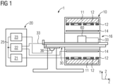
- Fig. 1 shows a schematic representation of an embodiment of a magnetic resonance imaging device 1 with a field camera 60 for the method according to the invention.
- the magnet unit 10 has a field magnet 11 that generates a static magnetic field B0 for aligning nuclear spins of samples or the patient in a recording area.
- the recording area is characterized by an extremely homogeneous static magnetic field B0, whereby the homogeneity particularly affects the magnetic field strength or magnitude.
- the recording area is almost spherical and arranged in a patient tunnel 16 that extends in a longitudinal direction 2 through the magnet unit 10.
- a patient bed 30 is movable in the patient tunnel 16 by the traversing unit 36.
- the field magnet 11 is typically a superconducting magnet that can generate magnetic fields with a magnetic flux density of up to 3T, and even higher in the latest devices. However, permanent magnets or electromagnets with normally conducting coils can also be used for lower field strengths.
- the magnet unit 10 has gradient coils 12, which are designed to superimpose variable magnetic fields in three spatial directions on the magnetic field B0 for spatial differentiation of the acquired imaging regions in the examination volume.
- the gradient coils 12 are typically coils made of normally conducting wires that can generate mutually orthogonal fields in the examination volume.
- the magnet unit 10 also has a body coil 14 which is designed to radiate a high-frequency signal supplied via a signal line into the examination volume and to receive resonance signals emitted by the patient 100 and to emit them via a signal line.
- a control unit 20 supplies the magnet unit 10 with the various signals for the gradient coils 12 and the body coil 14 and evaluates the received signals.
- the control unit 20 has a gradient control 21 which is designed to supply the gradient coils 12 with variable currents via supply lines, which provide the desired gradient fields in the examination volume in a time-coordinated manner.
- control unit 20 has a radio-frequency unit 22, which is designed to generate a radio-frequency pulse with a predetermined temporal profile, amplitude, and spectral power distribution for exciting a magnetic resonance of the nuclear spins in the patient 100.
- Pulse powers in the kilowatt range can be achieved.
- the excitation pulses can be transmitted into the patient 100 via the body coil 14 or via a local transmitting antenna.
- a controller 23 communicates via a signal bus 25 with the gradient controller 21 and the high-frequency unit 22.
- a field camera 60 is arranged instead of the patient in order to measure the magnetic field in the patient tunnel 16.
- the field camera 60 has, as in Fig. 2 and Fig. 3 shown, probes 61 and receiving antennas 62, wherein the receiving antennas 62 are in signal connection with receivers of the radio frequency unit 22 via a connecting line 33.
- the signal connection can also be wireless.
- Fig. 2 the samples 61 of a field camera 60 are shown schematically.
- the field camera 60 has a number M of samples 61, which are preferably distributed on the surface of a spatial volume 70 to be measured.
- the samples 61 comprise a material active with respect to nuclear magnetic resonance. These can be hydrogen-containing samples 61, such as water or hydrocarbon compounds. Liquid samples 61 can be contained in cuvettes or vials.
- the samples 61 can be embedded in a matrix or a structural body that does not itself exhibit nuclear magnetic resonance or is active at a different frequency.
- the size of the samples 61 is a compromise between spatial resolution and sensitivity. The larger the samples 61, the lower the spatial resolution.
- the spatial volume 70 is depicted here as a cube to simplify the representation of the orientation of the spatial axes.
- the spatial volume 70 can also take any other shape; for example, a sphere, ellipsoid, cylinder, prism, or similar arrangements that at least partially fill the recording area are also conceivable.
- One or more concentric spherical shells on which the samples 61 are arranged are also advantageous, since, due to the magnetic field laws, the fields inside a source-free volume can be determined from the fields on the surface.
- the samples 61 are arranged in such a way that only one lies on a plane perpendicular to a gradient vector. This allows the Fig. 4 explained method to distinguish the samples 61 based on the Larmor frequency under the influence of the magnetic gradient.
- interference coils 63 are provided around the individual samples 61, which can be supplied with a direct or high-frequency current in order to allow any existing excitation to decay more quickly so that the next measurement can follow more quickly.
- the relative sensitivity of the individual receiving antennas 62 for the individual samples 61 can also be determined by means of several magnetic resonance images of the samples 61 with projection onto a two-dimensional surface or a one-dimensional line.
- the receiving antennas 62 of the field camera 61 are shown as an example in a separate Fig. 3
- the receiving antennas 62 each have a receiving volume 64 and are arranged relative to the spatial volume to be measured such that two of the M samples are arranged in at least one of the receiving volumes 64 and the receiving volumes 64 are at least partially disjoint and at least one sample is arranged in each receiving volume.
- the number N of Receiving antennas is greater than or equal to the number M of samples.
- FIG. 3 A possible configuration of receiving antennas 62 of the field camera 60 is shown.
- the receiving antennas 62 are shown here as antenna coils.
- the spatial volume 70 is at least partially surrounded by the receiving antennas 62.
- the samples 61 within the spatial volume 70 are in Fig. 3 For the sake of clarity, they are not shown, but are shown as in Fig. 2 shown arranged within the spatial volume 70.
- the receiving antennas 61 are arranged on the outside circumference of a hollow body. As shown, this can also be, for example, a head coil, which, as in a known model with 64 individual receiving coils as receiving antennas 62, receives magnetic resonance signals from the interior, in which the spatial volume 70 with the samples 61 is arranged.
- a field camera can be provided with an existing head coil by using a cost-effective passive matrix with the samples 61.
- the idea of the present invention is that the signals of the individual samples 61 can be recovered from the reception signals of the reception antennas 62 if the signals of the M samples 61 form a solvable linear system of equations with the N antenna reception signals.
- the number N of receiving antennas 62 is greater than or at least equal to the number M of samples. Furthermore, the signals from all samples 61 must be received by at least one receiving antenna 62 each.
- Fig. 3 a receiving volume 64 for a receiving antenna 62 is indicated. The contour indicates the area over which signals from samples 61 are attenuated by a predetermined value compared to a sample in the center of the antenna coil; within the scope of the claimed invention, this value is 40 dB.
- the reception volume 64 is maximally limited by the distance at which the reception signal falls below the noise level.
- the reception volume 64 of the reception antenna 62 is Fig. 3 a club-shaped structure that extends radially inward. The radially outward lobe is not shown for clarity.
- the solvability of the system of equations requires that the reception volumes 64 of two receiving antennas 62 are not identical, in the sense that both receiving antennas 62 deliver the same signal levels, or signal levels scaled by the same factor, for the same samples 61.
- a 1:1 assignment of receiving antennas 62 to samples 61 is not required; rather, some receiving antennas 62 can cover a large reception volume 64, while others detect only a single sample 61.
- a magnetic field gradient is applied, in which each sample 61 is exposed to a different static magnetic field consisting of magnetic field B0 and gradient field. Then, either only a single sample 61 can be excited with a narrowband excitation pulse, and the individual signal of this sample 61 can be evaluated by the receiving antennas 62.
- the signals from all samples 61 could be received with all receiving antennas 62 and separated in the frequency domain based on the different frequencies. Measures for improved frequency separation are described below for the method according to the invention.
- interference coils 63 around the individual samples, to selectively excite one sample at a time with an excitation pulse via this interference coil 63.
- An exemplary head coil with 64 receiving antennas 62 could therefore, in conjunction with up to 64 samples 61, measure a magnetic field inside the head coil. To do so, it is merely necessary to arrange the samples 61 in a matrix or a shaped body as already described and then position this in a predetermined position in the head coil, so that, as already described, individual excitation and different received signals are possible. It is also conceivable to use resonant coils on the samples as a first resonant circuit to improve the coupling of the samples 61 to the excitation pulse and/or the receiving antennas 62, thus improving the signal strength and the SNR. The first resonant circuit can also have two different resonant frequencies, e.g., by coupling two resonant circuits, so that signal amplification is possible even with different static B0 fields.
- Fig. 4 a schematic flow chart of a method according to the invention for measuring a magnetic field distribution with a magnetic resonance imaging device 1 and a field camera 60 is given.
- a sensitivity matrix for the receiving antennas with a sensitivity E mn for each sample m at each receiving antenna n is acquired. For this purpose, it is necessary to determine the signal response for at least M, or better still N, with N > M, for a predetermined excitation of each sample m.
- Receiving antennas 62. For a signal vector with the magnetic resonance signals S m of the M samples 61 and an antenna signal vector with the received signals A n of the N receiving antennas 62, the system of equations results: A n E mn ⁇ S m
- One possible embodiment for determining the matrix elements of the sensitivity matrix is to excite each of the M samples 61 individually one after the other. This can be achieved, for example, by generating a magnetic field gradient in a step S120, in which each of the M samples 61 is exposed to a magnetic field of different magnitude. This can be achieved, as already described, by arranging the samples relative to the magnetic field gradient such that only one sample 61 is arranged in a plane perpendicular to the gradient vector. Either the samples 61 are aligned in the X, Y, or Z direction according to a gradient vector of the individual gradient coils 12, so that it is sufficient to apply current to the respective gradient coil 12. Or, a suitable gradient vector is determined in a step S110, and a gradient vector in a suitable direction relative to the samples 61 is generated in a step S120 by superimposing the fields of the three gradient coils 12.
- each of the M samples is exposed to a different magnetic field composed of the gradient magnetic field and the static magnetic field B0, they also exhibit different Larmor frequencies.
- a narrowband excitation pulse with the respective Larmor frequency can then be used to individually excite a single sample, and the magnetic resonance signal of this single sample 61 can then be received by all N receiving antennas 62 to detect the respective matrix elements of the sensitivity matrix E mn .
- the frequency spacing is insufficient for clean separation, it is also conceivable to increase the selectivity by weighting the received signals of the receiving antennas 62 with a window function such as the Hann or Gaussian function. Furthermore, exponentially increasing weighting can compensate for the natural decay of the magnetic resonance signal and reduce the linewidth.
- an inverse matrix I nm is determined for the sensitivity matrix E mn .
- the sensitivity matrix E mn specifies a system of equations that is reversible under certain conditions, so that the received signals or the amplitude A n of the receiving antennas 62 can be used to determine the magnetic resonance signals of the individual samples 61.
- the system of equations of the sensitivity matrix E mn is not underdetermined. If the system of equations is overdetermined, i.e., the number N of receiving antennas 62 is greater than the number M of samples 61 and the arrangement of the samples 61 relative to the receiving antennas 62 is such that non-identical linear combinations of signals from samples 61 are detected in different receiving antennas 62, a pseudoinverse matrix I nm can be determined from the sensitivity matrix using self-value decomposition or R modification. From this, in turn, a solution with minimal separation and improved signal-to-noise ratio for the magnetic resonance signals S m of the samples 61 can be determined using the least squares method.
- the inversion of the matrix can be carried out, for example, in a control unit 20 of the magnetic resonance imaging device 1, but a separate computing unit or a computing unit used for image reconstruction would also be conceivable.
- N antenna signals A n of the M samples 61 are detected in a magnetic field to be measured by means of the N receiving antennas 62.
- an excitation of the samples 61 by an excitation pulse with the Larmor frequency at an expected magnetic field B0 Since the separation of the magnetic resonance signals of the individual samples 61 is subsequently carried out based on the spatial diversity of the sensitivity matrix E mn or its inverse I nm , it is not necessary to expose the individual samples 61 to a different magnetic field using a gradient.
- the excitation can therefore be carried out with a narrowband common excitation pulse whose frequency is the Larmor frequency of the samples 61 at the expected static magnetic field B0.
- the bandwidth of the excitation pulse only needs to be large enough to compensate for inhomogeneities in the static magnetic field B0.
- the N amplitude values or the vector of the antenna signals A n of the M samples 61 are then recorded using the receiving antennas 62.
- a step S320 the magnetic resonance signals S m of the individual samples 62 are then determined by multiplying the vector AN by the inverse matrix I nm .
- a pseudo-inverse matrix or a system of equations which can be solved, for example, using the least squares method, is used instead of the quadratic inverse matrix.
- the inverse matrix remains unchanged as long as the sensitivity matrix is not altered, for example, by spatial changes.
- the inverse matrix can be used for rapid calculation of the magnetic resonance signals for a large number of rapidly consecutive measurements.
- the evaluation is preferably carried out on the control unit 20 of the magnetic resonance tomograph 1
- the magnetic field value thus determined can be output to a user via a display to evaluate the homogeneity of the magnetic field B0.
- the control unit 20 determines a setting for shim currents through shimming coils of the magnetic resonance imaging device 1 from the B0 values and outputs this setting to improve the homogeneity of the static magnetic field B0.
Landscapes
- Physics & Mathematics (AREA)
- Condensed Matter Physics & Semiconductors (AREA)
- General Physics & Mathematics (AREA)
- High Energy & Nuclear Physics (AREA)
- Engineering & Computer Science (AREA)
- Artificial Intelligence (AREA)
- Computer Vision & Pattern Recognition (AREA)
- Health & Medical Sciences (AREA)
- General Health & Medical Sciences (AREA)
- Nuclear Medicine, Radiotherapy & Molecular Imaging (AREA)
- Radiology & Medical Imaging (AREA)
- Signal Processing (AREA)
- Magnetic Resonance Imaging Apparatus (AREA)
Claims (9)
- Procédé de mesure d'une répartition du champ magnétique dans un volume d'espace à mesurer comprenant un tomodensitomètre (1) par résonnance magnétique et une caméra (60) à champ de détection d'une répartition du champ magnétique au moyen d'une mesure de résonnance magnétique, dans lequel la caméra (60) à champ a :un nombre de M prises (61), qui sont répartis sur le volume (70) d'espace à mesurer ;un nombre de N antennes (62) de réception, dans lequel les antennes (62) de réception ont chacune un volume (64) de réception, dans lequel le signal de résonnance magnétique, provoqué par une prise dans l'antenne de réception, n'est pas amorti de plus de 40 dB par rapport à un signal maximum pouvant être produit par la prise et sont disposées, relativement au volume (70) d'espace à mesurer, de manière à ce que au moins deux des M prises (61) soient disposées dans au moins l'un des volumes (64) de réception et de manière à ce que les volumes (64) de réception soient disjoints au moins en partie et de manière à ce qu'au moins une prise (61) soit disposée dans chaque volume (64) de réception,dans lequel le nombre N des antennes (62) de réception est supérieur ou égal au nombre M des prises (61),dans lequel le procédé comporte les stades :(S100) détection, par le tomodensitomètre (1) par résonnance magnétique, d'une matrice de sensibilité pour les antennes (62) de réception avec une sensibilité Emn pour chaque prise (61) m sur chaque antenne (62) de réception n ;(S200) détection, par le tomodensitomètre (1) par résonnance magnétique au moyen des N antennes (62) de réception, de N signaux An d'entrée des M prises (61) dans un champ magnétique à mesurer ;(S300) détermination, par une commande (23), des M signaux Sm de résonnance magnétique des diverses prises à partir des N signaux An d'antenne en fonction de la matrice Emn de sensibilité,dans lequel le tomodensitomètre (1) par résonnance magnétique a un système de gradient et la caméra (60) à champ est disposée dans le tomodensitomètre (1) par résonnance magnétique,caractérisé en ce quele stade (S100) de la détection d'une matrice de sensibilité comporte en outre des sous-stades :(S110) détermination d'un gradient de champ magnétique sous l'effet duquel chaque prise (61) est soumise à un champ magnétique différent ;(S120) production du gradient de champ déterminé au moyen du système de gradient pendant la détection de la matrice Emn de sensibilité.
- Procédé suivant la revendication 1, dans lequel le procédé comporte en outre le stade :(S310) détermination de la matrice Inm inverse de la matrice Emn de sensibilité ;(S320) détermination des signaux Sm de résonnance magnétique des diverses prises par multiplication d'un vecteur AN composé des N signaux d'antenne par la matrice Inm inverse.
- Procédé suivant la revendication 1, dans lequel le stade (S100) de la détection d'une matrice de sensibilité comporte en outre les sous-stades :
(S130) pondération des signaux d'antenne, par une fonction de fenêtre en fonction du temps, pour affiner une répartition spectrale pendant la détection de la matrice de sensibilité. - Procédé suivant l'une des revendications précédentes, dans lequel les N antennes (62) de réception de la caméra (60) à champ entourent le volume (70) d'espace au moins en partie en en faisant le tour à l'extérieur.
- Procédé suivant l'une des revendications précédentes, dans lequel au moins une prise (61) de la caméra (60) à champ a un premier circuit de résonnance ayant une résonnance à la fréquence de Larmor,
dans lequel la caméra à champ a un deuxième circuit de résonnance, dans lequel le premier circuit de résonnance est en couplage inductif avec le deuxième circuit de résonnance et le deuxième circuit de résonnance a une surface d'induction plus grande que le premier circuit de résonnance. - Procédé suivant la revendication 5, dans lequel le premier circuit de résonnance a une bobine et une capacité, dans lequel la capacité est formée d'extrémités de conducteur isolées torsadées de la bobine.
- Procédé suivant la revendication 5 ou 6, dans lequel le premier circuit de résonnance a deux fréquences de résonnance différentes.
- Produit de programme d'ordinateur, qui peut être chargé directement dans un processeur d'une commande (23) programmable d'un tomodensitomètre (1) par résonnance magnétique ayant une caméra (60) de champ suivant la revendication 1, comprenant des moyens de code de programme, pour exécuter tous les stades d'un procédé suivant l'une des revendications 1 à 7, lorsque le produit de programme est exécuté sur la commande (23).
- Support de mémoire, déchiffrable par ordinateur, ayant des informations de commande, déchiffrables électroniquement, qui y sont mises en mémoire et qui sont conformées de manière à ce qu'elles exécutent, lors de l'utilisation du support de mémoire dans une commande (23) d'un tomodensitomètre (1) par résonnance magnétique ayant une caméra (60) de champ suivant la revendication 1, le procédé suivant l'une des revendications 1 à 7.
Priority Applications (3)
| Application Number | Priority Date | Filing Date | Title |
|---|---|---|---|
| EP19162536.7A EP3709040B1 (fr) | 2019-03-13 | 2019-03-13 | Procédé de fonctionnement d'une caméra à champ magnétique |
| US16/800,199 US11243277B2 (en) | 2019-03-13 | 2020-02-25 | Passive field camera and method for operating the passive field camera |
| CN202010165078.4A CN111693912B (zh) | 2019-03-13 | 2020-03-11 | 利用磁共振断层成像设备和场照相机测量磁场分布的方法 |
Applications Claiming Priority (1)
| Application Number | Priority Date | Filing Date | Title |
|---|---|---|---|
| EP19162536.7A EP3709040B1 (fr) | 2019-03-13 | 2019-03-13 | Procédé de fonctionnement d'une caméra à champ magnétique |
Publications (2)
| Publication Number | Publication Date |
|---|---|
| EP3709040A1 EP3709040A1 (fr) | 2020-09-16 |
| EP3709040B1 true EP3709040B1 (fr) | 2025-04-30 |
Family
ID=65801995
Family Applications (1)
| Application Number | Title | Priority Date | Filing Date |
|---|---|---|---|
| EP19162536.7A Active EP3709040B1 (fr) | 2019-03-13 | 2019-03-13 | Procédé de fonctionnement d'une caméra à champ magnétique |
Country Status (3)
| Country | Link |
|---|---|
| US (1) | US11243277B2 (fr) |
| EP (1) | EP3709040B1 (fr) |
| CN (1) | CN111693912B (fr) |
Families Citing this family (6)
| Publication number | Priority date | Publication date | Assignee | Title |
|---|---|---|---|---|
| CN110381855B (zh) | 2017-01-06 | 2023-07-04 | 因赛普特有限责任公司 | 用于动脉瘤治疗装置的抗血栓涂层 |
| US11471582B2 (en) | 2018-07-06 | 2022-10-18 | Incept, Llc | Vacuum transfer tool for extendable catheter |
| US11766539B2 (en) | 2019-03-29 | 2023-09-26 | Incept, Llc | Enhanced flexibility neurovascular catheter |
| US11638637B2 (en) | 2019-12-18 | 2023-05-02 | Imperative Care, Inc. | Method of removing embolic material with thrombus engagement tool |
| US12201506B2 (en) | 2019-12-18 | 2025-01-21 | Imperative Care, Inc. | Rotatable thrombus engagement tool |
| US12171917B1 (en) | 2024-01-08 | 2024-12-24 | Imperative Care, Inc. | Devices for blood capture and reintroduction during aspiration procedure |
Family Cites Families (46)
| Publication number | Priority date | Publication date | Assignee | Title |
|---|---|---|---|---|
| US4680594A (en) | 1986-04-02 | 1987-07-14 | Optotech, Inc. | Single beam direct read during write and write protect system for use in an optical data storage system |
| US5543711A (en) * | 1994-11-22 | 1996-08-06 | Picker International, Inc. | Multiple quadrature volume coils for magnetic resonance imaging |
| US6029082A (en) * | 1997-11-24 | 2000-02-22 | Picker International, Inc. | Less-claustrophobic, quadrature, radio-frequency head coil for nuclear magnetic resonance |
| CN1111746C (zh) * | 1998-04-17 | 2003-06-18 | 皇家菲利浦电子有限公司 | 磁共振成象方法和装置 |
| DE10106830C2 (de) * | 2001-02-14 | 2003-01-16 | Siemens Ag | Verfahren zur Bilderzeugung mittels magnetischer Resonanz mit mehreren unabhängigen Empfangsantennen |
| AUPS224702A0 (en) * | 2002-05-10 | 2002-06-13 | Thorlock International Limited | Transmit - receive coil system for nuclear quadrupole resonance signal detection in substances |
| US7123012B2 (en) * | 2002-11-29 | 2006-10-17 | Advanced Imaging Research, Inc. | Multiple tuned radio frequency coil for resonance imaging and spectroscopic analysis |
| GB0307116D0 (en) * | 2003-03-27 | 2003-04-30 | Oxford Instr Superconductivity | Nuclear magnetic resonance apparatus |
| JP2006527617A (ja) * | 2003-06-19 | 2006-12-07 | コーニンクレッカ フィリップス エレクトロニクス エヌ ヴィ | 読み出し方向での感度エンコーディングのあるmr撮像 |
| US7366559B2 (en) * | 2003-06-26 | 2008-04-29 | Echo Medical Systems, Llc | Nuclear magnetic resonance apparatus and method for assessing whole body composition |
| US6919723B2 (en) * | 2003-07-09 | 2005-07-19 | General Electric Company | Method and apparatus to automatically maintain loop isolation in position variant MRI coils |
| DE10334170B3 (de) * | 2003-07-26 | 2005-06-02 | Physikalisch-Technische Bundesanstalt Braunschweig Und Berlin | Anordnung zum Erzeugen von Hochfrequenz-B1-Feldern in der NMR mit Flächenstromantennen |
| US7970452B2 (en) * | 2003-09-30 | 2011-06-28 | Hologic, Inc. | Open architecture imaging apparatus and coil system for magnetic resonance imaging |
| WO2005078470A2 (fr) * | 2004-02-10 | 2005-08-25 | Koninklijke Philips Electronics N.V. | Procede d'imagerie par resonance magnetique |
| EP1582886B1 (fr) * | 2004-04-02 | 2012-08-15 | Universität Zürich | Appareil à resonance magnétique avec des détecteurs de champ magnétique |
| JP5213698B2 (ja) * | 2005-04-28 | 2013-06-19 | コーニンクレッカ フィリップス エレクトロニクス エヌ ヴィ | マルチチャネル送信/受信アンテナ装置を動作させる方法及び回路構成 |
| WO2007003218A1 (fr) * | 2005-07-05 | 2007-01-11 | Commissariat A L'energie Atomique | Appareil destiné à une spectroscopie et/ou imagerie rmn haute résolution avec un facteur de remplissage et une amplitude de champ hf améliorés |
| DE102005056711B3 (de) * | 2005-11-28 | 2007-05-10 | Siemens Ag | Magnetresonanzanlage mit einem Grundkörper und einer Patientenliege |
| EP2147329A4 (fr) * | 2007-05-03 | 2012-03-21 | Ca Nat Research Council | Excitation spatialement sélective à base de radiofréquence en irm |
| DE102007030568A1 (de) * | 2007-07-02 | 2009-01-08 | Siemens Ag | Liegeeinrichtung mit einer Lokalantenneneinrichtung für ein Magnetresonanzgerät |
| DE102007047020B4 (de) | 2007-10-01 | 2012-07-12 | Siemens Ag | Anordnung zur Übertragung von Magnetresonanzsignalen |
| DE102009030721B4 (de) * | 2009-06-26 | 2013-04-04 | Siemens Aktiengesellschaft | SAR-Berechnung für mehrkanalige MR-Sendesysteme |
| WO2012001583A1 (fr) * | 2010-07-02 | 2012-01-05 | Koninklijke Philips Electronics N.V. | Imagerie par résonance magnétique parallèle utilisant des données de bobine sous-échantillonnées pour estimation de sensibilité de bobine |
| US8487615B2 (en) * | 2011-04-20 | 2013-07-16 | Imris Inc | Magnetic resonance signal detection using remotely positioned receive coils |
| EP2515132A1 (fr) * | 2011-04-22 | 2012-10-24 | Eidgenössische Technische Hochschule (ETH) | Agencement de caméra de champ dynamique pour applications de résonnance magnétique et procédés de fonctionnement associés |
| DE102012205333B4 (de) * | 2012-04-02 | 2015-05-28 | Siemens Aktiengesellschaft | Magnetresonanztomograph |
| DE102012209754B4 (de) * | 2012-06-12 | 2016-09-22 | Siemens Healthcare Gmbh | Spuleneinrichtung für einen Kernspintomographen |
| WO2014030084A1 (fr) * | 2012-08-22 | 2014-02-27 | Koninklijke Philips N.V. | Système et procédé pour un amplificateur paramétrique à mode équilibré |
| CN103767705B (zh) * | 2012-10-23 | 2017-12-22 | 三星电子株式会社 | 磁共振成像系统和磁共振成像方法 |
| KR101967242B1 (ko) * | 2012-11-14 | 2019-04-09 | 삼성전자주식회사 | 자기공명영상 시스템 및 자기공명영상 방법 |
| KR102001063B1 (ko) * | 2012-11-14 | 2019-07-17 | 삼성전자주식회사 | 자기공명영상 시스템 및 자기공명영상 방법 |
| US20140218025A1 (en) * | 2013-02-01 | 2014-08-07 | Agilent Technologies, Inc. | Transverse volume coils and related magnetic resonance systems and methods |
| KR102038630B1 (ko) * | 2013-02-04 | 2019-10-30 | 삼성전자주식회사 | 자기공명영상 시스템 |
| JP6353028B2 (ja) * | 2013-03-14 | 2018-07-04 | インビボ コーポレイション | 磁気共鳴画像診断用コイルシステム |
| US9606210B2 (en) * | 2013-09-04 | 2017-03-28 | Toshiba Medical Systems Corporation | Magnetic resonance imaging apparatus and magnetic resonance imaging method |
| US9476959B2 (en) * | 2013-09-04 | 2016-10-25 | Toshiba Medical Systems Corporation | MRI ghosting correction using unequal magnitudes ratio |
| WO2015144388A1 (fr) * | 2014-03-24 | 2015-10-01 | Koninklijke Philips N.V. | Antenne haute fréquence d'imagerie à résonance magnétique |
| DE102014213413B4 (de) | 2014-07-10 | 2018-12-20 | Siemens Healthcare Gmbh | Dynamische Felderfassung in einem MRT |
| KR102324731B1 (ko) * | 2014-09-19 | 2021-11-10 | 삼성전자주식회사 | 자기 공명 영상 장치용 수신 코일 |
| DE102014222938B4 (de) * | 2014-11-11 | 2016-08-18 | Siemens Healthcare Gmbh | MR-Lokalspulensystem, MR-System und Verfahren zum Betreiben desselben |
| EP3241042A4 (fr) * | 2014-12-30 | 2018-08-15 | Halliburton Energy Services, Inc. | Appareil, systèmes et procédés de mesure de résistivité rmn combinée |
| US10488475B2 (en) * | 2015-04-02 | 2019-11-26 | Imris, Inc. | Transceiver coil array facilitating MR-guided procedures |
| JP6865697B2 (ja) * | 2015-06-15 | 2021-04-28 | コーニンクレッカ フィリップス エヌ ヴェKoninklijke Philips N.V. | スタックオブスター獲得を使用したmr像形成 |
| RU2736557C2 (ru) * | 2016-10-10 | 2020-11-18 | Конинклейке Филипс Н.В. | Картирование функции градиентного импульсного отклика |
| US10802176B2 (en) * | 2017-02-14 | 2020-10-13 | Baker Hughes, A Ge Company, Llc | Methods and devices for magnetic resonance measurements using decoupled transmit antennas |
| US11193992B2 (en) * | 2017-05-05 | 2021-12-07 | Quality Electrodynamics, Llc | Single layer magnetic resonance imaging (MRI) transmit/receive (Tx/Rx) radio frequency (RF) coil with induced current failsafe protection |
-
2019
- 2019-03-13 EP EP19162536.7A patent/EP3709040B1/fr active Active
-
2020
- 2020-02-25 US US16/800,199 patent/US11243277B2/en active Active
- 2020-03-11 CN CN202010165078.4A patent/CN111693912B/zh active Active
Also Published As
| Publication number | Publication date |
|---|---|
| US20200292645A1 (en) | 2020-09-17 |
| CN111693912B (zh) | 2023-02-03 |
| EP3709040A1 (fr) | 2020-09-16 |
| CN111693912A (zh) | 2020-09-22 |
| US11243277B2 (en) | 2022-02-08 |
Similar Documents
| Publication | Publication Date | Title |
|---|---|---|
| EP3709040B1 (fr) | Procédé de fonctionnement d'une caméra à champ magnétique | |
| EP2100158B1 (fr) | Procédé d'obtention des courbes d'amplitude et de phase d'impulsions hf en vue d'une excitation spatiale sélective | |
| EP0074022B1 (fr) | Dispositif de tomographie à spin nucléaire | |
| DE102012212983B3 (de) | Vermeidung von Einfaltungsartefakten bei der Aufnahme von Magnetresonanzdaten | |
| EP3770624B1 (fr) | Procédés et dispositifs de prise en compte du signal de résonance magnétique lors d'un antiparasitage | |
| DE102011078680B3 (de) | Magnetfeldunempfindliche CEST-Bildgebung | |
| DE102012212376B3 (de) | Ermittlung einer Magnetresonanzsystem-Ansteuersequenz | |
| DE102012204624B4 (de) | Erfassung von MR-Daten in einem vorbestimmten Volumenabschnitt eines Untersuchungsobjekts | |
| DE19635019B4 (de) | Virtuelle Frequenzkodierung von erfaßten kernmagnetischen Resonanz-Bilddaten | |
| DE10354941B4 (de) | Bestimmung der B1-Feldstärke bei MR-Messungen | |
| DE102010043956B4 (de) | Erfassung von MR-Daten in einem vorbestimmten dreidimensionalen Volumenabschnitt unter Vermeidung von Einfaltungs- und Bandartefakten | |
| DE102011083871B4 (de) | Anpassung der Grundfrequenz eines HF-Anregungspulses bei der nicht-selektiven Anregung von Kernspinsignalen in einem Untersuchungsobjekt | |
| DE102015221888A1 (de) | Gleichzeitige MRT-Mehrschichtmessung | |
| DE19511835C2 (de) | Pulssequenz für ein Kernspintomographiegerät mit vorgegebener, zeitlich konstanter Inhomogenität in einer Raumrichtung und Vorrichtung zur Ausführung der Pulssequenz | |
| EP3001212A1 (fr) | Procede et installation de resonance magnetique destines a la reconstruction d'une image mr en tenant compte du deplacement chimique | |
| DE102012209295B4 (de) | Bestimmung einer objektspezifischen B1-Verteilung eines Untersuchungsobjekts im Messvolumen in der Magnetresonanztechnik | |
| DE102004052894B4 (de) | Optimiertes Verfahren zur Vermeidung von Einfaltungsartefakten in der Magnetresonanztomographie sowie Magnetresonanztomographiegerät und Computersoftwareprodukt | |
| DE102011082669B4 (de) | Hyperintense Darstellung von Bereichen im Umfeld von Dipolfeldern mittels MRI | |
| DE10152734B4 (de) | Gerät und Verfahren zur Magnet-Resonanz-Bildgebung bei gleichzeitiger Messung zweier benachbarter Schichten | |
| DE102010027312A1 (de) | Verfahren zur Erstellung von MR-Bildern sowie entsprechend ausgestaltete Magnetresonanzlage | |
| DE102005015069B4 (de) | Verfahren zur Vermeidung linearer Phasenfehler in der Magnetresonanz-Spektroskopie | |
| EP4332602B1 (fr) | Procédé d'acquisition de données d'image par résonance magnétique et appareil de résonance magnétique | |
| DE102010041659A1 (de) | Verfahren zur Erzeugung eines optimierten MR-Bildes eines Untersuchungsobjekts, Computerprogrammprodukt, elektronisch lesbarer Datenträger und Magnetresonanzgerät | |
| EP4465068A1 (fr) | Tomographe à résonance magnétique pour localiser des objets métalliques et procédé de fonctionnement | |
| DE102012222149B4 (de) | Verfahren zur Erzeugung von Magnetresonanzmessdaten |
Legal Events
| Date | Code | Title | Description |
|---|---|---|---|
| PUAI | Public reference made under article 153(3) epc to a published international application that has entered the european phase |
Free format text: ORIGINAL CODE: 0009012 |
|
| STAA | Information on the status of an ep patent application or granted ep patent |
Free format text: STATUS: THE APPLICATION HAS BEEN PUBLISHED |
|
| AK | Designated contracting states |
Kind code of ref document: A1 Designated state(s): AL AT BE BG CH CY CZ DE DK EE ES FI FR GB GR HR HU IE IS IT LI LT LU LV MC MK MT NL NO PL PT RO RS SE SI SK SM TR |
|
| AX | Request for extension of the european patent |
Extension state: BA ME |
|
| STAA | Information on the status of an ep patent application or granted ep patent |
Free format text: STATUS: REQUEST FOR EXAMINATION WAS MADE |
|
| 17P | Request for examination filed |
Effective date: 20210304 |
|
| RBV | Designated contracting states (corrected) |
Designated state(s): AL AT BE BG CH CY CZ DE DK EE ES FI FR GB GR HR HU IE IS IT LI LT LU LV MC MK MT NL NO PL PT RO RS SE SI SK SM TR |
|
| STAA | Information on the status of an ep patent application or granted ep patent |
Free format text: STATUS: EXAMINATION IS IN PROGRESS |
|
| 17Q | First examination report despatched |
Effective date: 20230208 |
|
| RAP1 | Party data changed (applicant data changed or rights of an application transferred) |
Owner name: SIEMENS HEALTHINEERS AG |
|
| GRAP | Despatch of communication of intention to grant a patent |
Free format text: ORIGINAL CODE: EPIDOSNIGR1 |
|
| STAA | Information on the status of an ep patent application or granted ep patent |
Free format text: STATUS: GRANT OF PATENT IS INTENDED |
|
| RIC1 | Information provided on ipc code assigned before grant |
Ipc: G01R 33/565 20060101ALN20241107BHEP Ipc: G01R 33/56 20060101ALI20241107BHEP Ipc: G01R 33/24 20060101AFI20241107BHEP |
|
| INTG | Intention to grant announced |
Effective date: 20241115 |
|
| GRAS | Grant fee paid |
Free format text: ORIGINAL CODE: EPIDOSNIGR3 |
|
| GRAA | (expected) grant |
Free format text: ORIGINAL CODE: 0009210 |
|
| STAA | Information on the status of an ep patent application or granted ep patent |
Free format text: STATUS: THE PATENT HAS BEEN GRANTED |
|
| REG | Reference to a national code |
Ref country code: DE Ref legal event code: R081 Ref document number: 502019013271 Country of ref document: DE Owner name: SIEMENS HEALTHINEERS AG, DE Free format text: FORMER OWNER: ANMELDERANGABEN UNKLAR / UNVOLLSTAENDIG, 80297 MUENCHEN, DE |
|
| AK | Designated contracting states |
Kind code of ref document: B1 Designated state(s): AL AT BE BG CH CY CZ DE DK EE ES FI FR GB GR HR HU IE IS IT LI LT LU LV MC MK MT NL NO PL PT RO RS SE SI SK SM TR |
|
| REG | Reference to a national code |
Ref country code: CH Ref legal event code: EP Ref country code: GB Ref legal event code: FG4D Free format text: NOT ENGLISH |
|
| REG | Reference to a national code |
Ref country code: DE Ref legal event code: R096 Ref document number: 502019013271 Country of ref document: DE |
|
| REG | Reference to a national code |
Ref country code: IE Ref legal event code: FG4D Free format text: LANGUAGE OF EP DOCUMENT: GERMAN |
|
| REG | Reference to a national code |
Ref country code: NL Ref legal event code: MP Effective date: 20250430 |
|
| PG25 | Lapsed in a contracting state [announced via postgrant information from national office to epo] |
Ref country code: ES Free format text: LAPSE BECAUSE OF FAILURE TO SUBMIT A TRANSLATION OF THE DESCRIPTION OR TO PAY THE FEE WITHIN THE PRESCRIBED TIME-LIMIT Effective date: 20250430 Ref country code: PT Free format text: LAPSE BECAUSE OF FAILURE TO SUBMIT A TRANSLATION OF THE DESCRIPTION OR TO PAY THE FEE WITHIN THE PRESCRIBED TIME-LIMIT Effective date: 20250901 Ref country code: FI Free format text: LAPSE BECAUSE OF FAILURE TO SUBMIT A TRANSLATION OF THE DESCRIPTION OR TO PAY THE FEE WITHIN THE PRESCRIBED TIME-LIMIT Effective date: 20250430 |
|
| REG | Reference to a national code |
Ref country code: LT Ref legal event code: MG9D |
|
| PG25 | Lapsed in a contracting state [announced via postgrant information from national office to epo] |
Ref country code: NO Free format text: LAPSE BECAUSE OF FAILURE TO SUBMIT A TRANSLATION OF THE DESCRIPTION OR TO PAY THE FEE WITHIN THE PRESCRIBED TIME-LIMIT Effective date: 20250730 Ref country code: GR Free format text: LAPSE BECAUSE OF FAILURE TO SUBMIT A TRANSLATION OF THE DESCRIPTION OR TO PAY THE FEE WITHIN THE PRESCRIBED TIME-LIMIT Effective date: 20250731 |
|
| PG25 | Lapsed in a contracting state [announced via postgrant information from national office to epo] |
Ref country code: PL Free format text: LAPSE BECAUSE OF FAILURE TO SUBMIT A TRANSLATION OF THE DESCRIPTION OR TO PAY THE FEE WITHIN THE PRESCRIBED TIME-LIMIT Effective date: 20250430 Ref country code: NL Free format text: LAPSE BECAUSE OF FAILURE TO SUBMIT A TRANSLATION OF THE DESCRIPTION OR TO PAY THE FEE WITHIN THE PRESCRIBED TIME-LIMIT Effective date: 20250430 |
|
| PG25 | Lapsed in a contracting state [announced via postgrant information from national office to epo] |
Ref country code: BG Free format text: LAPSE BECAUSE OF FAILURE TO SUBMIT A TRANSLATION OF THE DESCRIPTION OR TO PAY THE FEE WITHIN THE PRESCRIBED TIME-LIMIT Effective date: 20250430 |
|
| PG25 | Lapsed in a contracting state [announced via postgrant information from national office to epo] |
Ref country code: HR Free format text: LAPSE BECAUSE OF FAILURE TO SUBMIT A TRANSLATION OF THE DESCRIPTION OR TO PAY THE FEE WITHIN THE PRESCRIBED TIME-LIMIT Effective date: 20250430 |
|
| PG25 | Lapsed in a contracting state [announced via postgrant information from national office to epo] |
Ref country code: RS Free format text: LAPSE BECAUSE OF FAILURE TO SUBMIT A TRANSLATION OF THE DESCRIPTION OR TO PAY THE FEE WITHIN THE PRESCRIBED TIME-LIMIT Effective date: 20250731 |
|
| PG25 | Lapsed in a contracting state [announced via postgrant information from national office to epo] |
Ref country code: IS Free format text: LAPSE BECAUSE OF FAILURE TO SUBMIT A TRANSLATION OF THE DESCRIPTION OR TO PAY THE FEE WITHIN THE PRESCRIBED TIME-LIMIT Effective date: 20250830 |
|
| PG25 | Lapsed in a contracting state [announced via postgrant information from national office to epo] |
Ref country code: LV Free format text: LAPSE BECAUSE OF FAILURE TO SUBMIT A TRANSLATION OF THE DESCRIPTION OR TO PAY THE FEE WITHIN THE PRESCRIBED TIME-LIMIT Effective date: 20250430 |
|
| PG25 | Lapsed in a contracting state [announced via postgrant information from national office to epo] |
Ref country code: SM Free format text: LAPSE BECAUSE OF FAILURE TO SUBMIT A TRANSLATION OF THE DESCRIPTION OR TO PAY THE FEE WITHIN THE PRESCRIBED TIME-LIMIT Effective date: 20250430 Ref country code: DK Free format text: LAPSE BECAUSE OF FAILURE TO SUBMIT A TRANSLATION OF THE DESCRIPTION OR TO PAY THE FEE WITHIN THE PRESCRIBED TIME-LIMIT Effective date: 20250430 |
|
| PG25 | Lapsed in a contracting state [announced via postgrant information from national office to epo] |
Ref country code: CZ Free format text: LAPSE BECAUSE OF FAILURE TO SUBMIT A TRANSLATION OF THE DESCRIPTION OR TO PAY THE FEE WITHIN THE PRESCRIBED TIME-LIMIT Effective date: 20250430 |
|
| PG25 | Lapsed in a contracting state [announced via postgrant information from national office to epo] |
Ref country code: EE Free format text: LAPSE BECAUSE OF FAILURE TO SUBMIT A TRANSLATION OF THE DESCRIPTION OR TO PAY THE FEE WITHIN THE PRESCRIBED TIME-LIMIT Effective date: 20250430 |
|
| PG25 | Lapsed in a contracting state [announced via postgrant information from national office to epo] |
Ref country code: SK Free format text: LAPSE BECAUSE OF FAILURE TO SUBMIT A TRANSLATION OF THE DESCRIPTION OR TO PAY THE FEE WITHIN THE PRESCRIBED TIME-LIMIT Effective date: 20250430 Ref country code: RO Free format text: LAPSE BECAUSE OF FAILURE TO SUBMIT A TRANSLATION OF THE DESCRIPTION OR TO PAY THE FEE WITHIN THE PRESCRIBED TIME-LIMIT Effective date: 20250430 |
|
| PG25 | Lapsed in a contracting state [announced via postgrant information from national office to epo] |
Ref country code: IT Free format text: LAPSE BECAUSE OF FAILURE TO SUBMIT A TRANSLATION OF THE DESCRIPTION OR TO PAY THE FEE WITHIN THE PRESCRIBED TIME-LIMIT Effective date: 20250430 |
|
| REG | Reference to a national code |
Ref country code: DE Ref legal event code: R097 Ref document number: 502019013271 Country of ref document: DE |
|
| PLBE | No opposition filed within time limit |
Free format text: ORIGINAL CODE: 0009261 |
|
| STAA | Information on the status of an ep patent application or granted ep patent |
Free format text: STATUS: NO OPPOSITION FILED WITHIN TIME LIMIT |
|
| REG | Reference to a national code |
Ref country code: CH Ref legal event code: L10 Free format text: ST27 STATUS EVENT CODE: U-0-0-L10-L00 (AS PROVIDED BY THE NATIONAL OFFICE) Effective date: 20260311 |
|
| 26N | No opposition filed |
Effective date: 20260202 |
|
| PGFP | Annual fee paid to national office [announced via postgrant information from national office to epo] |
Ref country code: FR Payment date: 20260316 Year of fee payment: 8 |