EP2100528B1 - Helm - Google Patents
Helm Download PDFInfo
- Publication number
- EP2100528B1 EP2100528B1 EP08252641A EP08252641A EP2100528B1 EP 2100528 B1 EP2100528 B1 EP 2100528B1 EP 08252641 A EP08252641 A EP 08252641A EP 08252641 A EP08252641 A EP 08252641A EP 2100528 B1 EP2100528 B1 EP 2100528B1
- Authority
- EP
- European Patent Office
- Prior art keywords
- inserting plate
- helmet
- neck pad
- fitting part
- engaging part
- Prior art date
- Legal status (The legal status is an assumption and is not a legal conclusion. Google has not performed a legal analysis and makes no representation as to the accuracy of the status listed.)
- Not-in-force
Links
Images





Classifications
-
- A—HUMAN NECESSITIES
- A42—HEADWEAR
- A42B—HATS; HEAD COVERINGS
- A42B3/00—Helmets; Helmet covers ; Other protective head coverings
- A42B3/04—Parts, details or accessories of helmets
- A42B3/10—Linings
- A42B3/105—Linings with additional protection for the neck
-
- A—HUMAN NECESSITIES
- A42—HEADWEAR
- A42B—HATS; HEAD COVERINGS
- A42B3/00—Helmets; Helmet covers ; Other protective head coverings
- A42B3/04—Parts, details or accessories of helmets
- A42B3/0406—Accessories for helmets
- A42B3/0473—Neck restraints
-
- A—HUMAN NECESSITIES
- A42—HEADWEAR
- A42B—HATS; HEAD COVERINGS
- A42B3/00—Helmets; Helmet covers ; Other protective head coverings
- A42B3/04—Parts, details or accessories of helmets
- A42B3/06—Impact-absorbing shells, e.g. of crash helmets
-
- A—HUMAN NECESSITIES
- A42—HEADWEAR
- A42B—HATS; HEAD COVERINGS
- A42B3/00—Helmets; Helmet covers ; Other protective head coverings
- A42B3/04—Parts, details or accessories of helmets
- A42B3/10—Linings
- A42B3/12—Cushioning devices
Definitions
- This invention relates to a neck pad attachment structure in a helmet for use by the driver and/or passengers while operating various types of mobile vehicles such as a motorcycle, a four-wheeled automobile, watercraft such as a motorboat or moving equipment such as a bicycle.
- JP H06 4028 U Japanese Utility Model Laid-Open Publication No. JP H06 4028 U , for example, is referred to.
- This Japanese Utility Model Laid-Open Publication No. H06-4028U provides a description about an attachment structure for removably attaching the neck pad that is installed on a helmet for use by the driver and/or passengers while operating various types of mobile vehicles such as a motorcycle and a four-wheeled automobile, watercraft such as a motorboat or moving equipment such as a bicycle.
- the aforesaid neck pad attachment structure is made such that a vertical side part (an inserting plate) arranged at the neck pad is inserted between the shell and the shock absorbing liner, the fitting part of the vertical side part is fitted to the engaging part of the shock absorbing liner under its inserted state so as to cause the attached state of the neck pad to be held. It is further disclosed that under this attached state, it has actions and effects such that when a tension force acts against the neck pad in a direction in which the neck pad is pulled out of the shell, the fitting part moves to the engaging part and their fitted state becomes more rigid.
- the aforesaid neck pad attachment structure is constituted such that the vertical side part is inserted between the shell and the shock absorbing liner when the neck pad is attached to the helmet, and the fitting part rides over the engaging part and is fitted to and attached to the engaging part.
- the end part of the neck pad (the end part of the engaging member constituting the neck pad) is pulled out in an outward direction to cause the fitting state of the fitting part in respect to the engaging part to be released from the end part toward the central part, thereby the neck pad is removed.
- the aforesaid removal of the neck pad generates both resistance caused by a contact between the fitting part and the engaging part and resistance caused by deformations of the fitting part and the engaging part when the fitted state of the fitting part in respect to the engaging part is released because the aforesaid removal is carried out by a pulling operation in which the fitted state becomes rigid, thereby a certain pulling force is required due to the resistances.
- a subject of this invention is an object to assure a positive characteristic of the neck pad fitted state and perform an easy removal of the neck pad by a smaller force.
- the neck pad attachment structure of this invention includes at least the following constitution
- a neck pad attachment structure in which a neck pad for improving the comfort of the wearer and/or stability of a helmet at the time of wearing the helmet is removably attached to the helmet and provided with an inserting plate that can be freely inserted in an opening direction of a helmet putting-on or taking-off opening part into a clearance between a shell constituting an outer-most layer of the helmet and a shock absorbing liner installed in the shell characterized in that the attachment structure enables the inserting plate to be moved along a peripheral direction of the putting-on or taking-off opening part within the clearance, the inserting plate is provided with a fitting part and in turn an engaging part where the fitting part is oppositely fitted in a pulling-out direction of the inserting plate installed within the clearance, the fitting part and/or the engaging part has resiliency acting in a thickness direction of the helmet and when the inserting plate is inserted into the clearance in the case that the neck pad is attached, the fitting part rides over the engaging part under resiliency, and upon completion of insertion, the fitting part is resilient
- the neck pad attachment structure is characterized in that there is provided biasing means for biasing the inserting plate toward the engaging part and motion of the inserting plate in its thickness direction within the clearance is restricted by a biasing force of the biasing means.
- the helmet as defined in this invention may be applied in any of a full-face type helmet or a open-face type helmet as long as it has a constitution in which the neck pad is installed in it.
- the neck pad as defined in this invention is a member contacted with the neck part of the helmet-wearer and installed at a scope ranging from the rear head part of the helmet putting-on or taking-off opening to the side head portions.
- the neck pad of this invention has a function for assuring comfort and/or stability of the helmet when wearing the helmet with each of the members constituting the inner liners such as a head pad in contact with the head part, cheek pads in contact with the cheek portions and a chin pad contacted with the chin part of a helmet-wearer (a full-face type helmet) and the like, respectively.
- the inner liners are constituted such that some cushion members molded by urethane foam, or raw material having softness similar to that of the urethane foam, into shapes corresponding to the neck, head, cheeks and chin in the helmet are enclosed by a cover member having softness and/or elasticity.
- the shell as defined in this invention constitutes the outer-most layer of the helmet that is moulded into a predetermined shape (a full-face type helmet shape, a open-face type helmet shape), for example, by applying fibre reinforced resin material (GFRP, CFRP and the like) immersed with thermosetting resin material (epoxy resin material, phenol resin material and the like) or thermoplastic resin material (polycarbonate and the like) to fibre reinforced material (carbon fibre, glass fibre and the like).
- GFRP fibre reinforced resin material
- CFRP thermosetting resin material
- polycarbonate and the like polycarbonate and the like
- the shock absorbing liner as defined in this invention is one that is molded into a shape corresponding to the head part of the shell by applying foamed polystyrene material or raw material having a shock absorbing performance similar to that of polystyrene material and the shock absorbing liner is installed inside the shell.
- the helmet putting-on or taking-off opening as defined in this invention is an opening through which a helmet-wearer puts on or takes off a helmet onto or from their head, and this opening faces downward (toward the shoulders of the helmet-wearer) when the person has the helmet on.
- a shape of the putting-on or taking-off opening in a full-face type helmet is an elliptical shape enclosing an entire periphery of the neck part of the helmet-wearer
- a shape of the putting-on or taking-off opening in a open-face type helmet is a semi-circle shape enclosing a scope ranging from the rear head part to the side head portions of the helmet-wearer.
- the attachment structure for a neck pad 1 in this preferred embodiment is illustrated as a constitution applied to a full-face type helmet A (hereinafter called "helmet").
- helmet A full-face type helmet A
- the configuration of the helmet A in this preferred embodiment is schematically illustrated.
- the helmet A in this preferred embodiment is a full-face type helmet having a well-known configuration including a shell 1A in which a front side opening 11A is opened for exposing the face of a helmet-wearer and a putting-on or taking-off opening 12A is provided for the helmet-wearer to put on or take off the helmet A.
- a shock absorbing liner 2A is installed inside the shell 1A
- an inner liner 3A constituted of a head pad, cheek pads and a chin pad or the like (not shown) is installed inside the shock absorbing liner 2A.
- the neck pad 1 is removably installed at a location corresponding to the scope ranging from the rear head part to side head portions of the putting-on or taking-off opening 12A, and a shield 4A is provided for use in opening and closing the front side opening 11A.
- the front side opening 11A is defined as a front side and the putting-on or taking-off opening 12A is defined as a lower side, respectively.
- the neck pad 1 of the preferred embodiment is constituted of a horseshoe-shaped pad main body 11 and an inserting plate 12 vertically installed from the pad main body 11 in a vertical direction.
- the pad main body 11 has a cushioning characteristic in which a cushion member (not shown), and the pad main body 11 is a member contacted around the neck part of the helmet-wearer.
- the inserting plate 12 is a thin plate member made of synthetic resin material such as polyamide resin or the like, (for example, nylon ( a registered trademark of E.I.
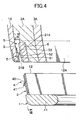
- the attachment structure for the neck pad 1 will be described as follows. As shown in Figs. 2 to 8 , the attachment structure in this preferred embodiment is constituted by three fitting members 2 fixed to the inserting plate 12, and an engaging member 3 fixed to the shell 1A. Insertion of the inserting plate 12 causes the fitting member 2 to be resiliently fitted against the engaging member 3, thereby the neck pad 1 is attached. The inserting plate 12 is moved in a peripheral direction under a state in which the inserting plate 12 is inserted to cause the fitting member 2 to be released from its fitted state in respect to the engaging member 3 and then the neck pad 1 is removed.
- the fitting member 2 is a resilient thin plate made of synthetic resin material such as polyamide resin, for example, wherein one fitting member is fixed at a rear central part of the neck pad 1 and each of the fitting members is fixed at both sides with the rear central part being applied as an interface, respectively.
- the surface of the fitting member 2 oppositely facing against the engaging member 3 is formed with a fitting part 4.
- the fitting part 4 has slits at three sides except its upper side, and the lower extremity end 41 is cut and raised to extend from the upper base end 42 toward the engaging member 3. That is, the fitting part 4 having a configuration as above provides a rearward repelling force (a biasing force) against a forward pushing force, so that it can be recovered back to its original shape from its forward crushed deformation.
- the engaging member 3 is a band-like resilient thin plate made of synthetic resin material such as polyamide resin and is fixed to the inside part of the shell 1A so as to oppositely face to the fitting member 2.
- Three engaging portions 5 each of which is fitted to the fitting part 4 are integrally protruded at the surface of the engaging member 3 oppositely facing against the fitting part 4.
- the engaging part 5 is formed with an inclined surface part 52 extending from the lower base end 51 in an upward direction toward the fitting part 4, and an engaging surface 53 to which the extremity end 41 of the fitting part 4 contacts from above and fits it is formed flat in a peripheral direction at the upper end of the inclined surface part 52.
- Fitting operation of the fitting part 4 having the aforesaid configuration in respect to the engaging part 5 is carried out in such a way that when the neck pad 1 is fixed, the inserting plate 12 is inserted into the helmet with the fitting part 4 oppositely faced against the engaging part 5 in a vertical direction, the extremity end 41 of the fitting part 4 moves upward while in contact with the inclined surface 52 of the engaging part 5, and the fitting part 4 is crushed forwardly as this motion occurs and is deformed.
- the extremity end 41 rides over the inclined surface 52 and the fitting part 4 is recovered into its original shape from its crushed deformation shape under an action of repelling force concurrently with the riding-over action, thereby the extremity end 41 is brought into a fitted state in which it is oppositely engaged from above to the engaging surface 53 of the engaging part 5.
- the shock absorbing liner 2A is provided with biasing means 6 for applying a biasing force against the inserting plate 12 inserted into the clearance S toward the engaging part 5.
- the biasing means 6 is made of a resilient material such as resilient urethane foam or rubber material that generates a repelling force (a biasing force) for returning from a crushed deformation to its original shape, and this biasing means is stored in a storing cavity 21A formed in the shock absorbing liner 2A.
- the biasing means 6 is adhered in the storing cavity 21A under a state in which it is protruded out of a rear opening part 21B of the storing cavity 21A.
- the biasing means 6 When the inserting plate 12 is inserted into the clearance S, the biasing means 6 is crushed and deformed by the inserting plate 12, and a repelling force for recovering its shape into its original shape concurrently with this crushed deformation may act to cause the inserting plate 12 to be pushed toward the engaging part 5. Then, forward or rearward motion of the inserting plate 12 within the clearance S is restricted by pushing the inserting plate 12 toward the engaging part 5 with this repelling force, and a positive holding of the fitting part 4 on the engaging part 5 under its fitted state can be attained.
- the storing cavity 21A is formed at a location strictly opposite to the fitting part 4 under its fitted state in a forward or rearward direction, and the repelling force of the biasing means 6 is concentrically acted against the fitting part 4, thereby more positive holding of fitted state of the fitting part 4 on the engaging part 5 is assured.
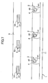
- removing step figures of Figs. 5 to 8A and 8B a removing operation for the neck pad 1 performed through a fixing structure of the neck pad 1 of this preferred embodiment will be described.
- the removing step figures schematically illustrate the operation when releasing a fitted state of the fitting part 4 and the engaging part 5.
- the removing operation for the neck pad 1 is carried out in such a way that the neck pad main body 11 is held by hand, the inserted inserting plate 12 is moved along a peripheral direction of the helmet A, the extremity end 41 of the fitting part 4 is move to a non-opposite position of the engaging surface 53 of the engaging part 5, thereby the fitted state of the fitting part 4 on the engaging part 5 is released, allowing the inserting plate 12 to be removed out of the clearance S.
- the pad main body 11 is pulled down to cause the inserting plate 12 to be pulled out of the clearance S and the neck pad 1 can be taken out.
- the attachment structure for the neck pad 1 in this preferred embodiment enables the neck pad 1 to be removed by moving the inserting plate 12 in a peripheral direction and pulling out the inserting plate 12. Further, releasing of the fitted state of the fitting part 4 in respect to the engaging part 5 is carried out under a state in which the extremity end 41 of the fitting part 4 moves on the engaging surface 53 of the engaging part 5 in a peripheral direction. Accordingly, a smooth releasing operation for the fitted state can be carried out under low resistance at the time of releasing of the fitted state with a low force. Further, since the engaging surface 32 is flat in its peripheral direction, the releasing operation for the fitted state can be carried out from any direction in the peripheral direction.
- the attachment structure for the neck pad 1 in this preferred embodiment enables a removal of the neck pad 1 to be easily carried out with a smaller force with a positive attached state of the neck pad 1 assured.
- marks indicating the attaching position may be attached to the neck pad 1 and the shell 1A or the neck pad 1 and the shock absorbing liner 2A (not shown).
- the attachment structure for the neck pad 1 is illustrated in a form in which the engaging member 3 is fixed to the shell 1A, the engaging member 3 may be fixed to the shock absorbing liner 2A (not shown).
- the attachment structure for the neck pad 1 is illustrated with the fitting member 2 formed with the fitting part 4 being fixed to the inserting plate 12 as a separate member, the fitting part 4 may be directly formed at the inserting plate 12 (not shown).
- the attachment structure for the neck pad 1 is illustrated under a form in which the fitting part 4 has a resiliency and is engaged with the engaging part 5 with this resiliency, the engaging part 5 may have resiliency and the fitting part 4 is engaged with the engaging part 5 with this resiliency (not shown).
- the attachment structure for the neck pad 1 is illustrated under a state with the biasing means 6 arranged at a location where it is accurately opposed against the fitting part 4, the biasing means 6 may be arranged over an entire length of the inserting plate 12 or arranged at a part including all the fitting parts 4 (not shown).
Landscapes
- Helmets And Other Head Coverings (AREA)
Claims (2)
- Anbringungsstruktur für ein Nackenpolster, bei der ein Nackenpolster (1) zur Verbesserung des Komforts des Trägers und/oder der Stabilität eines Helms (A) beim Tragen des Helms (A) abnehmbar an dem Helm (A) angebracht ist und mit einer Einsetzplatte (12) versehen ist, die in einer Öffnungsrichtung eines Helmaufsetz- oder absetzöffnungsteils (12A) frei in einen Zwischenraum (S) zwischen einer Schale (1A), die eine äußerste Schicht des Helms (A) bildet, und einer in der Schale (1A) angebrachten Stoßdämpfungsauskleidung (2A) eingesetzt werden kann, dadurch gekennzeichnet, dass die Anbringungsstruktur das Bewegen der Einsetzplatte (12) entlang einer peripheren Richtung des Aufsetz- oder Absetzöffnungsteils in dem Zwischenraum (S) ermöglicht,
die Einsetzplatte (12) mit einem Befestigungsteil (2) und wiederum einem Eingriffsteil (3) versehen ist, wobei der Befestigungsteil in einer Herausziehrichtung der in dem Zwischenraum (S) angebrachten Einsetzplatte (12) gegenüberliegend angebracht ist,
das Befestigungsteil (2) und/oder das Eingriffsteil (3) in einer Dickenrichtung des Helms wirkende Elastizität hat und, wenn die Einsetzplatte (12) in dem Fall, dass das Nackenpolster (1) angebracht wird, in den Zwischenraum (S) eingesetzt wird, das Befestigungsteil (2) unter Elastizität über das Eingriffsteil (3) reitet, und das Befestigungsteil (2) nach Beendigung des Einsetzens in einer Richtung, in der das Befestigungsteil (2) verhindert, dass die Einsetzplatte (12) herausgezogen wird, federnd an dem Eingriffsteil (3) angebracht ist und das Befestigungsteil (2), während sich die Einsetzplatte (12) in einer peripheren Richtung bewegt, sich auf eine nicht gegenüberliegende Position in Bezug auf das Eingriffsteil (3) bewegt, um das Lösen des befestigten Zustands des Eingriffsteils (3) zu verursachen, wodurch die Einsetzplatte (12) herausgezogen werden kann. - Anbringungsstruktur für ein Nackenpolster nach Anspruch 1, dadurch gekennzeichnet, dass ein Vorspannmittel (6) zum Vorspannen der Einsetzplatte (12) in Richtung auf das Eingriffsteil (3) vorgesehen ist und die Bewegung der Einsetzplatte (12) in ihrer Dickenrichtung innerhalb des Zwischenraums (S) von einer Vorspannkraft des Vorspannmittels (6) eingeschränkt wird.
Applications Claiming Priority (1)
| Application Number | Priority Date | Filing Date | Title |
|---|---|---|---|
| JP2008056286A JP5232505B2 (ja) | 2008-03-06 | 2008-03-06 | ネックパッドの取付け構造 |
Publications (3)
| Publication Number | Publication Date |
|---|---|
| EP2100528A2 EP2100528A2 (de) | 2009-09-16 |
| EP2100528A3 EP2100528A3 (de) | 2011-04-06 |
| EP2100528B1 true EP2100528B1 (de) | 2012-06-06 |
Family
ID=40933174
Family Applications (1)
| Application Number | Title | Priority Date | Filing Date |
|---|---|---|---|
| EP08252641A Not-in-force EP2100528B1 (de) | 2008-03-06 | 2008-08-06 | Helm |
Country Status (6)
| Country | Link |
|---|---|
| US (1) | US8327465B2 (de) |
| EP (1) | EP2100528B1 (de) |
| JP (1) | JP5232505B2 (de) |
| KR (1) | KR101376646B1 (de) |
| CN (1) | CN101524194B (de) |
| TW (1) | TWI402042B (de) |
Families Citing this family (14)
| Publication number | Priority date | Publication date | Assignee | Title |
|---|---|---|---|---|
| JP3023578B2 (ja) | 1992-09-16 | 2000-03-21 | 大同ほくさん株式会社 | 定温保存物の管理輸送方法 |
| WO2005120264A1 (ja) * | 2004-06-07 | 2005-12-22 | Shoei Co., Ltd. | フルフェイス型ヘルメット用ネックカバーおよびフルフェイス型ヘルメット |
| JP5495708B2 (ja) * | 2009-10-20 | 2014-05-21 | 株式会社谷沢製作所 | 繊維強化熱硬化性樹脂製ヘルメットおよび繊維強化熱硬化性樹脂製ヘルメットの製造方法 |
| JP5214672B2 (ja) * | 2010-07-23 | 2013-06-19 | 株式会社アライヘルメット | ヘルメットの頬パッド |
| IT1403501B1 (it) * | 2011-01-19 | 2013-10-17 | Mavet S R L | Paranuca per casco. |
| KR101772124B1 (ko) | 2015-11-30 | 2017-09-12 | 주식회사 기도스포츠 | 헬멧의 탈착식 패드 체결 구조 및 이를 포함하는 헬멧 |
| US11026467B2 (en) * | 2016-05-05 | 2021-06-08 | Fox Head, Inc. | In-molded helmet chinbar |
| EP3558044B1 (de) * | 2017-01-25 | 2022-05-11 | Bell Sports, Inc. | Helm mit integriertem schulterpolster |
| EP3516976B1 (de) * | 2017-12-22 | 2021-04-28 | Jonifer Enterprises Pty Ltd | Haarhalter für einen helm |
| IT201900009375A1 (it) | 2019-06-18 | 2020-12-18 | Alpinestars Res Spa | Casco protettivo |
| US20240090612A1 (en) * | 2021-02-05 | 2024-03-21 | Shoei Co., Ltd. | Helmet and method for manufacturing helmet |
| CA3223369A1 (en) * | 2022-12-15 | 2024-06-15 | Bombardier Recreational Products Inc. | Connectable helmet |
| EP4467032A1 (de) * | 2023-05-25 | 2024-11-27 | MAHLE International GmbH | Entlüftungsmodul für einen zweiradhelm |
| FR3152212B1 (fr) * | 2023-08-24 | 2026-02-13 | Shark | Ensemble de garniture de rembourrage intérieure pour un casque, et casque associé |
Family Cites Families (29)
| Publication number | Priority date | Publication date | Assignee | Title |
|---|---|---|---|---|
| US1823229A (en) * | 1930-03-10 | 1931-09-15 | Balbaud Paul | Separable fastener |
| US3734551A (en) * | 1971-06-28 | 1973-05-22 | Latch Plastics Inc | Closure-fastener for cabinets or the like |
| CH649450A5 (it) * | 1982-04-26 | 1985-05-31 | Hanspeter Hoffmann | Casco protettivo con collare di trattenuta alla testa dell'utente. |
| JPS59133630U (ja) * | 1983-02-25 | 1984-09-07 | 昭栄化工株式会社 | ヘルメツトの顎ベルト装置 |
| IT1169648B (it) * | 1983-10-28 | 1987-06-03 | Pier Luigi Nava | Casco integrale particolarmente per usi sportivi |
| IT1176690B (it) * | 1984-09-10 | 1987-08-18 | Pier Luigi Nava | Dispositivo di protezione applicabile a caschi particolarmente per uso sportivo |
| US4660259A (en) * | 1986-08-01 | 1987-04-28 | Minigrip, Inc. | Twist resistant reclosable extruded plastic fastener |
| JPH06405Y2 (ja) | 1990-04-24 | 1994-01-05 | 新日本製鐵株式会社 | 玉掛け合図帽 |
| JPH0760294B2 (ja) | 1992-06-16 | 1995-06-28 | 重光電気株式会社 | ディスプレイ装置 |
| JPH064028U (ja) * | 1992-06-18 | 1994-01-18 | 株式会社アライヘルメット | ヘルメットにおける後頭部保持部材の取付構造 |
| US5469606A (en) * | 1993-02-11 | 1995-11-28 | Hansen; Arne | Clamp means for joining objects together |
| JP2521467Y2 (ja) * | 1993-05-14 | 1996-12-25 | 萬利 張 | 接続管 |
| JPH086006Y2 (ja) * | 1993-07-28 | 1996-02-21 | 昭栄化工株式会社 | 乗車用ヘルメット |
| JP3955127B2 (ja) * | 1997-05-19 | 2007-08-08 | 学 根本 | ヘルメット |
| JP3733232B2 (ja) * | 1998-01-30 | 2006-01-11 | Ykk株式会社 | テープ付雌雄形係止具 |
| JP3004264B1 (ja) * | 1998-10-30 | 2000-01-31 | 株式会社アライヘルメット | フルフェース型ヘルメット |
| US6003212A (en) * | 1999-01-28 | 1999-12-21 | Imahata; Takeo | Pair of shoes fastener |
| CN2407525Y (zh) * | 2000-02-04 | 2000-11-22 | 陈煌期 | 免持听筒安全帽装置 |
| JP2001356400A (ja) * | 2000-06-15 | 2001-12-26 | Cosina Co Ltd | バヨネット連結装置 |
| US6289521B1 (en) * | 2000-08-30 | 2001-09-18 | Shoei Co., Ltd. | Helmet chin cover and helmet attached with chin cover |
| AUPR474501A0 (en) * | 2001-05-03 | 2001-05-31 | Cleveland, Paul | Protective collar |
| DE10226398B4 (de) * | 2002-06-13 | 2012-12-06 | Carl Zeiss Ag | Verfahren und Vorrichtung zum Erfassen der Lage eines Objekts im Raum |
| DE10238745A1 (de) * | 2002-08-21 | 2004-03-18 | Schuberth Werk Gmbh | Integralhelm |
| CN2598377Y (zh) * | 2003-02-28 | 2004-01-14 | 曹润起 | 缓冲安全帽 |
| KR100478155B1 (ko) * | 2003-04-28 | 2005-03-25 | 주식회사 홍진에이치제이씨 | 헬멧용 브레스 가드 조립체 |
| WO2005120264A1 (ja) * | 2004-06-07 | 2005-12-22 | Shoei Co., Ltd. | フルフェイス型ヘルメット用ネックカバーおよびフルフェイス型ヘルメット |
| FR2886520A1 (fr) | 2005-06-03 | 2006-12-08 | Msa Gallet Sa | Dispositif de fixation d'un bavolet a un casque de protection |
| CN2852761Y (zh) * | 2005-06-09 | 2007-01-03 | 东莞市安特尔运动器材有限公司 | 一种可更换外壳的头盔 |
| JP4948893B2 (ja) | 2006-05-09 | 2012-06-06 | 株式会社Shoei | ヘルメットおよびその脱着方法 |
-
2008
- 2008-03-06 JP JP2008056286A patent/JP5232505B2/ja active Active
- 2008-04-01 TW TW097111827A patent/TWI402042B/zh active
- 2008-05-07 KR KR1020080042505A patent/KR101376646B1/ko active Active
- 2008-05-30 CN CN2008101084244A patent/CN101524194B/zh active Active
- 2008-07-30 US US12/219,893 patent/US8327465B2/en active Active
- 2008-08-06 EP EP08252641A patent/EP2100528B1/de not_active Not-in-force
Also Published As
| Publication number | Publication date |
|---|---|
| JP5232505B2 (ja) | 2013-07-10 |
| CN101524194B (zh) | 2011-06-22 |
| KR20090096277A (ko) | 2009-09-10 |
| JP2009209502A (ja) | 2009-09-17 |
| HK1135002A1 (en) | 2010-05-28 |
| US8327465B2 (en) | 2012-12-11 |
| EP2100528A2 (de) | 2009-09-16 |
| TWI402042B (zh) | 2013-07-21 |
| TW200938109A (en) | 2009-09-16 |
| CN101524194A (zh) | 2009-09-09 |
| KR101376646B1 (ko) | 2014-03-20 |
| US20090222977A1 (en) | 2009-09-10 |
| EP2100528A3 (de) | 2011-04-06 |
Similar Documents
| Publication | Publication Date | Title |
|---|---|---|
| US8327465B2 (en) | Neck pad attachment structure (helmet) | |
| EP2311336B1 (de) | Open-Face-Helm | |
| EP2550884B1 (de) | Visierbefestigungsmechanismus bei einem Helm | |
| JP3955127B2 (ja) | ヘルメット | |
| US20070226880A1 (en) | Helmet | |
| US6226803B1 (en) | Helmet | |
| US20020148032A1 (en) | Protective helmet and means for connection of an accessory | |
| KR960010938B1 (ko) | 승차용 헬멧 | |
| JP2904416B1 (ja) | フルフェース型ヘルメット | |
| JP2012026056A (ja) | ヘルメットの頬パッド | |
| US20240315377A1 (en) | Protective helmet | |
| KR102677056B1 (ko) | 헬멧 | |
| HK1135002B (zh) | 颈垫的安装结构 | |
| EP4230072A1 (de) | Helm und wangenpolster | |
| JP2012021242A (ja) | 頚部装着具 | |
| HK1164627A (en) | Cheek pad for helmet and helmet |
Legal Events
| Date | Code | Title | Description |
|---|---|---|---|
| PUAI | Public reference made under article 153(3) epc to a published international application that has entered the european phase |
Free format text: ORIGINAL CODE: 0009012 |
|
| AK | Designated contracting states |
Kind code of ref document: A2 Designated state(s): AT BE BG CH CY CZ DE DK EE ES FI FR GB GR HR HU IE IS IT LI LT LU LV MC MT NL NO PL PT RO SE SI SK TR |
|
| AX | Request for extension of the european patent |
Extension state: AL BA MK RS |
|
| PUAL | Search report despatched |
Free format text: ORIGINAL CODE: 0009013 |
|
| AK | Designated contracting states |
Kind code of ref document: A3 Designated state(s): AT BE BG CH CY CZ DE DK EE ES FI FR GB GR HR HU IE IS IT LI LT LU LV MC MT NL NO PL PT RO SE SI SK TR |
|
| AX | Request for extension of the european patent |
Extension state: AL BA MK RS |
|
| 17P | Request for examination filed |
Effective date: 20110512 |
|
| AKX | Designation fees paid |
Designated state(s): AT BE BG CH CY CZ DE DK EE ES FI FR GB GR HR HU IE IS IT LI LT LU LV MC MT NL NO PL PT RO SE SI SK TR |
|
| GRAP | Despatch of communication of intention to grant a patent |
Free format text: ORIGINAL CODE: EPIDOSNIGR1 |
|
| GRAS | Grant fee paid |
Free format text: ORIGINAL CODE: EPIDOSNIGR3 |
|
| GRAA | (expected) grant |
Free format text: ORIGINAL CODE: 0009210 |
|
| AK | Designated contracting states |
Kind code of ref document: B1 Designated state(s): AT BE BG CH CY CZ DE DK EE ES FI FR GB GR HR HU IE IS IT LI LT LU LV MC MT NL NO PL PT RO SE SI SK TR |
|
| REG | Reference to a national code |
Ref country code: GB Ref legal event code: FG4D |
|
| REG | Reference to a national code |
Ref country code: AT Ref legal event code: REF Ref document number: 560593 Country of ref document: AT Kind code of ref document: T Effective date: 20120615 Ref country code: CH Ref legal event code: EP Ref country code: CH Ref legal event code: NV Representative=s name: ABREMA AGENCE BREVET ET MARQUES, GANGUILLET |
|
| REG | Reference to a national code |
Ref country code: IE Ref legal event code: FG4D |
|
| REG | Reference to a national code |
Ref country code: NL Ref legal event code: T3 |
|
| REG | Reference to a national code |
Ref country code: DE Ref legal event code: R096 Ref document number: 602008016155 Country of ref document: DE Effective date: 20120802 |
|
| REG | Reference to a national code |
Ref country code: SE Ref legal event code: TRGR |
|
| PG25 | Lapsed in a contracting state [announced via postgrant information from national office to epo] |
Ref country code: NO Free format text: LAPSE BECAUSE OF FAILURE TO SUBMIT A TRANSLATION OF THE DESCRIPTION OR TO PAY THE FEE WITHIN THE PRESCRIBED TIME-LIMIT Effective date: 20120906 Ref country code: FI Free format text: LAPSE BECAUSE OF FAILURE TO SUBMIT A TRANSLATION OF THE DESCRIPTION OR TO PAY THE FEE WITHIN THE PRESCRIBED TIME-LIMIT Effective date: 20120606 Ref country code: CY Free format text: LAPSE BECAUSE OF FAILURE TO SUBMIT A TRANSLATION OF THE DESCRIPTION OR TO PAY THE FEE WITHIN THE PRESCRIBED TIME-LIMIT Effective date: 20120606 Ref country code: LT Free format text: LAPSE BECAUSE OF FAILURE TO SUBMIT A TRANSLATION OF THE DESCRIPTION OR TO PAY THE FEE WITHIN THE PRESCRIBED TIME-LIMIT Effective date: 20120606 |
|
| REG | Reference to a national code |
Ref country code: AT Ref legal event code: MK05 Ref document number: 560593 Country of ref document: AT Kind code of ref document: T Effective date: 20120606 |
|
| REG | Reference to a national code |
Ref country code: LT Ref legal event code: MG4D Effective date: 20120606 |
|
| PG25 | Lapsed in a contracting state [announced via postgrant information from national office to epo] |
Ref country code: LV Free format text: LAPSE BECAUSE OF FAILURE TO SUBMIT A TRANSLATION OF THE DESCRIPTION OR TO PAY THE FEE WITHIN THE PRESCRIBED TIME-LIMIT Effective date: 20120606 Ref country code: GR Free format text: LAPSE BECAUSE OF FAILURE TO SUBMIT A TRANSLATION OF THE DESCRIPTION OR TO PAY THE FEE WITHIN THE PRESCRIBED TIME-LIMIT Effective date: 20120907 Ref country code: HR Free format text: LAPSE BECAUSE OF FAILURE TO SUBMIT A TRANSLATION OF THE DESCRIPTION OR TO PAY THE FEE WITHIN THE PRESCRIBED TIME-LIMIT Effective date: 20120606 Ref country code: SI Free format text: LAPSE BECAUSE OF FAILURE TO SUBMIT A TRANSLATION OF THE DESCRIPTION OR TO PAY THE FEE WITHIN THE PRESCRIBED TIME-LIMIT Effective date: 20120606 |
|
| PG25 | Lapsed in a contracting state [announced via postgrant information from national office to epo] |
Ref country code: IS Free format text: LAPSE BECAUSE OF FAILURE TO SUBMIT A TRANSLATION OF THE DESCRIPTION OR TO PAY THE FEE WITHIN THE PRESCRIBED TIME-LIMIT Effective date: 20121006 Ref country code: AT Free format text: LAPSE BECAUSE OF FAILURE TO SUBMIT A TRANSLATION OF THE DESCRIPTION OR TO PAY THE FEE WITHIN THE PRESCRIBED TIME-LIMIT Effective date: 20120606 Ref country code: RO Free format text: LAPSE BECAUSE OF FAILURE TO SUBMIT A TRANSLATION OF THE DESCRIPTION OR TO PAY THE FEE WITHIN THE PRESCRIBED TIME-LIMIT Effective date: 20120606 Ref country code: EE Free format text: LAPSE BECAUSE OF FAILURE TO SUBMIT A TRANSLATION OF THE DESCRIPTION OR TO PAY THE FEE WITHIN THE PRESCRIBED TIME-LIMIT Effective date: 20120606 Ref country code: SK Free format text: LAPSE BECAUSE OF FAILURE TO SUBMIT A TRANSLATION OF THE DESCRIPTION OR TO PAY THE FEE WITHIN THE PRESCRIBED TIME-LIMIT Effective date: 20120606 Ref country code: CZ Free format text: LAPSE BECAUSE OF FAILURE TO SUBMIT A TRANSLATION OF THE DESCRIPTION OR TO PAY THE FEE WITHIN THE PRESCRIBED TIME-LIMIT Effective date: 20120606 |
|
| PG25 | Lapsed in a contracting state [announced via postgrant information from national office to epo] |
Ref country code: PL Free format text: LAPSE BECAUSE OF FAILURE TO SUBMIT A TRANSLATION OF THE DESCRIPTION OR TO PAY THE FEE WITHIN THE PRESCRIBED TIME-LIMIT Effective date: 20120606 Ref country code: PT Free format text: LAPSE BECAUSE OF FAILURE TO SUBMIT A TRANSLATION OF THE DESCRIPTION OR TO PAY THE FEE WITHIN THE PRESCRIBED TIME-LIMIT Effective date: 20121008 |
|
| PG25 | Lapsed in a contracting state [announced via postgrant information from national office to epo] |
Ref country code: MC Free format text: LAPSE BECAUSE OF NON-PAYMENT OF DUE FEES Effective date: 20120831 |
|
| PLBE | No opposition filed within time limit |
Free format text: ORIGINAL CODE: 0009261 |
|
| STAA | Information on the status of an ep patent application or granted ep patent |
Free format text: STATUS: NO OPPOSITION FILED WITHIN TIME LIMIT |
|
| PG25 | Lapsed in a contracting state [announced via postgrant information from national office to epo] |
Ref country code: DK Free format text: LAPSE BECAUSE OF FAILURE TO SUBMIT A TRANSLATION OF THE DESCRIPTION OR TO PAY THE FEE WITHIN THE PRESCRIBED TIME-LIMIT Effective date: 20120606 Ref country code: ES Free format text: LAPSE BECAUSE OF FAILURE TO SUBMIT A TRANSLATION OF THE DESCRIPTION OR TO PAY THE FEE WITHIN THE PRESCRIBED TIME-LIMIT Effective date: 20120917 |
|
| 26N | No opposition filed |
Effective date: 20130307 |
|
| REG | Reference to a national code |
Ref country code: IE Ref legal event code: MM4A |
|
| REG | Reference to a national code |
Ref country code: DE Ref legal event code: R097 Ref document number: 602008016155 Country of ref document: DE Effective date: 20130307 |
|
| PG25 | Lapsed in a contracting state [announced via postgrant information from national office to epo] |
Ref country code: IE Free format text: LAPSE BECAUSE OF NON-PAYMENT OF DUE FEES Effective date: 20120806 Ref country code: BG Free format text: LAPSE BECAUSE OF FAILURE TO SUBMIT A TRANSLATION OF THE DESCRIPTION OR TO PAY THE FEE WITHIN THE PRESCRIBED TIME-LIMIT Effective date: 20120906 |
|
| PG25 | Lapsed in a contracting state [announced via postgrant information from national office to epo] |
Ref country code: MT Free format text: LAPSE BECAUSE OF FAILURE TO SUBMIT A TRANSLATION OF THE DESCRIPTION OR TO PAY THE FEE WITHIN THE PRESCRIBED TIME-LIMIT Effective date: 20120606 |
|
| PG25 | Lapsed in a contracting state [announced via postgrant information from national office to epo] |
Ref country code: TR Free format text: LAPSE BECAUSE OF FAILURE TO SUBMIT A TRANSLATION OF THE DESCRIPTION OR TO PAY THE FEE WITHIN THE PRESCRIBED TIME-LIMIT Effective date: 20120606 |
|
| PG25 | Lapsed in a contracting state [announced via postgrant information from national office to epo] |
Ref country code: LU Free format text: LAPSE BECAUSE OF NON-PAYMENT OF DUE FEES Effective date: 20120806 |
|
| PG25 | Lapsed in a contracting state [announced via postgrant information from national office to epo] |
Ref country code: HU Free format text: LAPSE BECAUSE OF FAILURE TO SUBMIT A TRANSLATION OF THE DESCRIPTION OR TO PAY THE FEE WITHIN THE PRESCRIBED TIME-LIMIT Effective date: 20080806 |
|
| PGFP | Annual fee paid to national office [announced via postgrant information from national office to epo] |
Ref country code: CH Payment date: 20150819 Year of fee payment: 8 |
|
| PGFP | Annual fee paid to national office [announced via postgrant information from national office to epo] |
Ref country code: SE Payment date: 20150819 Year of fee payment: 8 Ref country code: BE Payment date: 20150819 Year of fee payment: 8 Ref country code: NL Payment date: 20150830 Year of fee payment: 8 |
|
| REG | Reference to a national code |
Ref country code: FR Ref legal event code: PLFP Year of fee payment: 9 |
|
| PG25 | Lapsed in a contracting state [announced via postgrant information from national office to epo] |
Ref country code: BE Free format text: LAPSE BECAUSE OF NON-PAYMENT OF DUE FEES Effective date: 20160831 |
|
| REG | Reference to a national code |
Ref country code: SE Ref legal event code: EUG |
|
| REG | Reference to a national code |
Ref country code: CH Ref legal event code: PL |
|
| REG | Reference to a national code |
Ref country code: NL Ref legal event code: MM Effective date: 20160901 |
|
| PG25 | Lapsed in a contracting state [announced via postgrant information from national office to epo] |
Ref country code: LI Free format text: LAPSE BECAUSE OF NON-PAYMENT OF DUE FEES Effective date: 20160831 Ref country code: SE Free format text: LAPSE BECAUSE OF NON-PAYMENT OF DUE FEES Effective date: 20160807 Ref country code: CH Free format text: LAPSE BECAUSE OF NON-PAYMENT OF DUE FEES Effective date: 20160831 |
|
| PG25 | Lapsed in a contracting state [announced via postgrant information from national office to epo] |
Ref country code: NL Free format text: LAPSE BECAUSE OF NON-PAYMENT OF DUE FEES Effective date: 20160901 |
|
| REG | Reference to a national code |
Ref country code: FR Ref legal event code: PLFP Year of fee payment: 10 |
|
| REG | Reference to a national code |
Ref country code: FR Ref legal event code: PLFP Year of fee payment: 11 |
|
| PGFP | Annual fee paid to national office [announced via postgrant information from national office to epo] |
Ref country code: DE Payment date: 20240821 Year of fee payment: 17 |
|
| PGFP | Annual fee paid to national office [announced via postgrant information from national office to epo] |
Ref country code: GB Payment date: 20240823 Year of fee payment: 17 |
|
| PGFP | Annual fee paid to national office [announced via postgrant information from national office to epo] |
Ref country code: FR Payment date: 20240828 Year of fee payment: 17 |
|
| PGFP | Annual fee paid to national office [announced via postgrant information from national office to epo] |
Ref country code: IT Payment date: 20240827 Year of fee payment: 17 |
|
| REG | Reference to a national code |
Ref country code: DE Ref legal event code: R119 Ref document number: 602008016155 Country of ref document: DE |
|
| GBPC | Gb: european patent ceased through non-payment of renewal fee |
Effective date: 20250806 |
|
| PG25 | Lapsed in a contracting state [announced via postgrant information from national office to epo] |
Ref country code: GB Free format text: LAPSE BECAUSE OF NON-PAYMENT OF DUE FEES Effective date: 20250806 |
|
| PG25 | Lapsed in a contracting state [announced via postgrant information from national office to epo] |
Ref country code: IT Free format text: LAPSE BECAUSE OF NON-PAYMENT OF DUE FEES Effective date: 20250806 |
|
| PG25 | Lapsed in a contracting state [announced via postgrant information from national office to epo] |
Ref country code: DE Free format text: LAPSE BECAUSE OF NON-PAYMENT OF DUE FEES Effective date: 20260303 |
|
| PG25 | Lapsed in a contracting state [announced via postgrant information from national office to epo] |
Ref country code: FR Free format text: LAPSE BECAUSE OF NON-PAYMENT OF DUE FEES Effective date: 20250831 |