EP2100564A1 - Obturateur chirurgical - Google Patents
Obturateur chirurgical Download PDFInfo
- Publication number
- EP2100564A1 EP2100564A1 EP09161399A EP09161399A EP2100564A1 EP 2100564 A1 EP2100564 A1 EP 2100564A1 EP 09161399 A EP09161399 A EP 09161399A EP 09161399 A EP09161399 A EP 09161399A EP 2100564 A1 EP2100564 A1 EP 2100564A1
- Authority
- EP
- European Patent Office
- Prior art keywords
- knife carrier
- switching element
- knife
- protective cap
- tubular housing
- Prior art date
- Legal status (The legal status is an assumption and is not a legal conclusion. Google has not performed a legal analysis and makes no representation as to the accuracy of the status listed.)
- Granted
Links
- 230000001681 protective effect Effects 0.000 claims abstract description 99
- 238000005520 cutting process Methods 0.000 claims abstract description 71
- 238000006073 displacement reaction Methods 0.000 claims abstract description 34
- 230000004913 activation Effects 0.000 claims abstract description 3
- 230000000903 blocking effect Effects 0.000 claims description 15
- 230000009471 action Effects 0.000 description 7
- 239000007787 solid Substances 0.000 description 4
- 230000008901 benefit Effects 0.000 description 2
- 238000010276 construction Methods 0.000 description 2
- 230000007246 mechanism Effects 0.000 description 2
- 230000000149 penetrating effect Effects 0.000 description 2
- 230000007704 transition Effects 0.000 description 2
- 238000004140 cleaning Methods 0.000 description 1
- 230000002349 favourable effect Effects 0.000 description 1
- 238000000034 method Methods 0.000 description 1
- 230000008569 process Effects 0.000 description 1
- 230000000717 retained effect Effects 0.000 description 1
- 238000000926 separation method Methods 0.000 description 1
Images






Classifications
-
- A—HUMAN NECESSITIES
- A61—MEDICAL OR VETERINARY SCIENCE; HYGIENE
- A61B—DIAGNOSIS; SURGERY; IDENTIFICATION
- A61B17/00—Surgical instruments, devices or methods
- A61B17/34—Trocars; Puncturing needles
- A61B17/3494—Trocars; Puncturing needles with safety means for protection against accidental cutting or pricking, e.g. limiting insertion depth, pressure sensors
- A61B17/3496—Protecting sleeves or inner probes; Retractable tips
-
- A—HUMAN NECESSITIES
- A61—MEDICAL OR VETERINARY SCIENCE; HYGIENE
- A61B—DIAGNOSIS; SURGERY; IDENTIFICATION
- A61B17/00—Surgical instruments, devices or methods
- A61B17/34—Trocars; Puncturing needles
- A61B17/3417—Details of tips or shafts, e.g. grooves, expandable, bendable; Multiple coaxial sliding cannulas, e.g. for dilating
-
- A—HUMAN NECESSITIES
- A61—MEDICAL OR VETERINARY SCIENCE; HYGIENE
- A61B—DIAGNOSIS; SURGERY; IDENTIFICATION
- A61B17/00—Surgical instruments, devices or methods
- A61B17/34—Trocars; Puncturing needles
- A61B17/3417—Details of tips or shafts, e.g. grooves, expandable, bendable; Multiple coaxial sliding cannulas, e.g. for dilating
- A61B2017/3454—Details of tips
-
- A—HUMAN NECESSITIES
- A61—MEDICAL OR VETERINARY SCIENCE; HYGIENE
- A61B—DIAGNOSIS; SURGERY; IDENTIFICATION
- A61B17/00—Surgical instruments, devices or methods
- A61B17/34—Trocars; Puncturing needles
- A61B17/3417—Details of tips or shafts, e.g. grooves, expandable, bendable; Multiple coaxial sliding cannulas, e.g. for dilating
- A61B2017/3454—Details of tips
- A61B2017/3458—Details of tips threaded
-
- A—HUMAN NECESSITIES
- A61—MEDICAL OR VETERINARY SCIENCE; HYGIENE
- A61B—DIAGNOSIS; SURGERY; IDENTIFICATION
- A61B90/00—Instruments, implements or accessories specially adapted for surgery or diagnosis and not covered by any of the groups A61B1/00 - A61B50/00, e.g. for luxation treatment or for protecting wound edges
- A61B90/08—Accessories or related features not otherwise provided for
- A61B2090/0801—Prevention of accidental cutting or pricking
- A61B2090/08021—Prevention of accidental cutting or pricking of the patient or his organs
Definitions
- the invention relates to a surgical obturator for piercing a body wall with a tubular housing, with a displaceable in the tubular housing in the longitudinal direction between an advanced cutting position and a retracted protective position knife carrier on which a knife is held with a cutting edge in a correspondingly extending guide the tubular housing is guided, with a knife - catching, in the tubular housing in the longitudinal direction between an advanced rest position in which the knife is completely covered in its protective position, and a retracted working position sliding cap having a slot through which the cutting edge of the Knife passes and protrudes in the working position of the protective cap on this, and arranged with a arranged in the tubular housing, the knife from the cutting position in the protective position shifting rear zugs friendship, which can be activated by a displacement of the protective cap from the working position to the rest position.
- Such a surgical obturator is in German utility model 20 2006 008 405 U1 described.
- the retraction device is arranged in the grip area of the obturator, in which there is a relatively large amount of space available for a complex mechanism of the retraction device.
- the retraction device has a switching element which fixes the knife in the cutting position and releases upon activation for a displacement in the rest position, which is freely rotatable about the longitudinal axis of the tubular housing and longitudinally is mounted immovably in the tubular housing and which is rotatable to switch over a displacement of the knife carrier and / or the protective cap in the longitudinal direction of the tubular housing via a between the switching element on the one hand and the knife carrier and / or the protective cap on the other hand effective cam guide.
- the protective cap is acted upon by a spring, which shifts the protective cap from the working position to the rest position.
- the displacement of the protective cap in the working position thus takes place against the force of this spring.
- This spring is also responsible for the fact that the protective cap is no longer retained by the body wall after completely penetrating the body wall, but is advanced by the obturator generated by the opening in the rest position.
- the knife carrier is acted upon by a spring which moves the knife carrier from the cutting position into the protective position.
- This spring is responsible for the knife carrier is pushed back from the cutting position to the protective position after completion of the cutting process and by the displacement of the protective cap from the working position to the rest position, which activates the retraction device.
- the protective cap and the knife carrier are acted upon by a common spring pushing them apart, which on the one hand the protective cap from the working position to the rest position and on the other hand, the knife carrier shifts from the cutting position to the protective position.
- This spring has a double function in this construction.
- the spring is arranged in the interior of the knife carrier coil spring, which is supported on an entering through the wall of the knife carrier in the interior of the projection of the protective cap. Obtained in this way a very compact arrangement of protective cap, knife carrier and spring.
- the cutting edge of the knife may be rectilinear, but according to a preferred embodiment it is provided that the cutting edge of the knife is helical so that the knife carrier is displaced longitudinally relative to the tubular housing and the protective cap longitudinally displaced relative to the knife carrier relative to each other about the longitudinal axis the knife carrier are twisted. This rotation takes place by the guidance of the cutting edge in the tubular housing and by the guidance of the protective cap, which experiences this through the passing through the slot in the protective cap cutting edge.
- a helical guide of the cutting edge has the advantage that the surgeon when piercing the body wall can perform this particularly sensitive with a combined feed and rotary motion, also this embodiment has the advantage that the proportion of rotational movement experienced by the knife carrier and the cap , Can contribute to the rotation of the switching element.
- the blade carrier can advantageously have a sleeve-shaped shaft which is arranged concentrically to the tubular housing.
- the knife carrier is connected to a push rod which extends through the tubular housing up to a pressure device at the opposite end of the blade of the tubular housing.
- a push rod which may be provided for example with a push button, the knife carrier in the tubular housing in the longitudinal direction can be moved forward so that thereby the knife carrier passes from the retracted protective position in the advanced cutting position.
- the switching element is a sleeve concentrically surrounding the knife carrier. This concentric arrangement allows the placement of the parts in the smallest space and also allows optimal functioning of the effective between the knife carrier and switching element cam guide.
- the effective between the switching element and the knife carrier cam guide are formed by cam tracks and cams applied thereto, which are arranged on the outside of the knife carrier or the inner wall of the sleeve-shaped switching element.
- a working cycle is characterized in that the knife carrier once moved from its retracted protective position in the advanced cutting position, blocked there and after the complete piercing of the Body wall is released by shifting the cap from the working position to the rest position and pushed back into its retracted protective position, so that the arrangement again reaches the initial state.
- each cam track are associated with two cams, which abut one after the other on displacement of the blade carrier relative to the switching element on the cam track. These cams take over during the sliding movement of the knife carrier successively a rotation of the switching element.
- the cam track can be formed by the edge of an island-shaped projection on which the cams slide along a working cycle and thereby produce a rotational movement of the switching element.
- the knife carrier is advanced not only from the retracted protective position to the advanced cutting position, but even beyond.
- This further displacement beyond the cutting position serves to turn the switching element into a blocking position, so that upon retraction of the knife carrier in the direction of the cutting position a further return movement of the knife carrier is blocked by the stops, ie the knife remains in an advanced position.
- the stop on the switching element can be formed by a transverse to the longitudinal direction of the tubular housing extending third portion of the cam track. This also contributes to the simplification of the structure.
- the cam track and the cam between the switching element and the protective cap are formed by the lateral edges of teeth which are arranged on the mutually facing end faces of the protective cap and the switching element and in the pushed back into the working position cap in engagement stand.
- both the protective cap and the switching element carry on their facing end faces teeth that are not engaged, as long as the cap is in its advanced rest position, but come into engagement when the cap is retracted to the working position.
- the flanks of the teeth can be arranged and formed such that the teeth of the protective cap when retracting the protective cap from the rest position in the working position, the switching element from its blocking position in the first direction turn until the stop of the knife carrier reaches an obliquely to the longitudinal direction of the tubular housing fourth section of the cam track of the switching element, which adjoins the stop of the switching element. As soon as the stop of the knife carrier rests on this fourth section, the knife carrier exerts a force on the switching element under the action of the spring acting on it and tries to twist it in the second direction.
- such a rotation is prevented in that the flanks of the teeth are designed such that a rotation of the switching element in the second direction is limited under the influence of the abutment of the blade carrier abutting on the fourth section such that the blade carrier opposes his position when planting the two stops to each other only slightly pushed back into its cutting position.
- the blade carrier is thus blocked in a cutting position, which is pushed back only slightly compared to the blocking position, in this cutting position piercing the body wall can be done because the blade carrier is prevented by the switching element on pushing back in the direction of the protective position.
- the engagement of the teeth of the knife carrier and the protective cap is released upon displacement of the protective cap in the rest position, so that the limitation of the rotatability of the switching element is canceled.
- the knife carrier can be pushed back under the influence of the spring in the protective position, ie the displacement of the protective cap in the rest position triggers the return movement of the knife carrier.
- the cam track has a fifth section adjoining the fifth section, on which the front cam of the knife carrier slides when pushing back the knife carrier from the cutting position into the protective position and the switching element in the second direction in the starting position for twisted the next cycle.
- the rear cam of the knife carrier is in the position of the switching element in the blocking position and when abutment of the stop of the knife carrier at the fourth portion of the cam against a sixth portion of the cam track, which is a displacement of the knife carrier in the direction of the protective position Cutting position prevented.
- the knife is fixed in its position in the cutting position in both directions, so it can not be moved unintentionally by operating the push rod, the knife over the cutting position away to the front.
- the tubular housing 2 terminates in a part of the tubular housing 2 forming substantially circular cylindrical and tapered towards its front end 8 toward end cap 7, which is open at its front end 8.
- the end cap 7 surrounds an interior space 9 which, starting from the front end 8, has two successive step-shaped extensions 10, 11 and subsequently two successive step-shaped constrictions 12, 13, so that annular shoulder-shaped projections 14, 15, 16, 17 at these step-shaped extensions and constrictions arise ( FIG. 6 ).
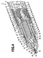
- the push rod 6 is fixedly connected to a cylindrical shaft 19 of a knife carrier 20, which passes through the entire interior 9 and carries at its front end 21 via this protruding knife 22 with a helical cutting edge 23, from a tip 24 to two opposite sides of the knife carrier 20 runs backwards ( FIG. 5 ).
- the cutting edge 23 engages a corresponding guide 25 in the inner wall of the end cap 7, this guide 25 is formed by a helical groove in the inner wall of the end cap 7.
- the blade carrier 20 undergoes an additional rotational movement about the longitudinal axis of the tubular housing 2 during advancement by the push rod 6.
- the knife 22 carrying the front portion of the blade carrier 20 is covered by a protective cap 27 which between the end cap 7 and the Knife carrier 20 is arranged and surrounding it on all sides.
- the protective cap 27 is closed at its front end 28 and tapers towards this front end 28, it has a helical slot 29, the contour of which corresponds to the helical cutting edge 23, which protrudes through this slot 29. Through this slot 29 and the protruding through this cutting edge 23, which is guided in the guide 25 of the end cap 7, and the protective cap 27 undergoes a rotation in a longitudinal displacement corresponding to the helical course of the cutting edge 23.
- the cap 27 carries at its rear end an annular flange extension 30 which forms an annular step 32 in the transition to the front, the knife 22 overlapping cylindrical portion 31 and at its rear edge 33 more evenly distributed over the circumference and in the direction of the rear End 3 of the housing 2 facing teeth 34 carries.
- the protective cap 27 is freely rotatable both in its front region 31 and in the region of the extension 30 in an annular space between the knife carrier 20 and the end cap 7 and displaceably mounted in the longitudinal direction, concentrically surrounding the knife carrier 20.
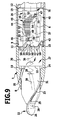
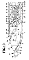
- the annular step 32 of the cap 27 is located on the projection 14 of the end cap 7, starting from this rest position, the cap 27 can be pulled into the end cap 7 to a pushed back working position in which the end in the rest position before the projection 15 Teeth 34 project beyond this projection 15 ( Figures 9 and 10 ).
- the displacement is small and limited to a portion of the depth of the teeth 34th
- a coil spring 36 is arranged concentrically to the blade carrier 20 and the protective cap 27, which on the one hand on the end face 37 of the push rod 6 and on the other hand supported on a projection 38 which is part of the protective cap 27 and which projects through a slot-shaped opening 39 in the wall of the knife carrier 20 in its interior 35.
- the cap 27 are moved to its rest position and the blade carrier 20 in its protective position, ie the cap 27 rests with its annular step 32 on the projection 14 and the blade carrier 20 with its rear edge 26 on the projection 17.
- the knife carrier 20 can be moved in the direction of the cutting position, as well as a shift of the cap 27 in the direction of the working position is possible.
- This switching element 40 carries at its front, the protective cap 27 facing edge 41 of the teeth 34 of the cap 27 opposite, evenly distributed over the circumference teeth 42, which are formed by outgoing from the edge 41 incisions 43.
- cams 46, 47 On the inside of the switching element 40 are uniformly distributed over the circumference several island-shaped projections 44, the outer edge of a cam track 45 for cams 46, 47 which are arranged on the shaft 19 of the knife carrier 20 and projecting from this radially outward.
- the shaft 19 carries a plurality of evenly distributed over the circumference front cam 46 and a plurality of equally spaced around the circumference rear cam 47, each located in a radial plane ( FIG. 5 ).
- These cams 46 and 47 can during the displacement of the blade carrier 20 in Longitudinally by contact with the cam tracks 45, the switching element 40 rotate, the front and the rear cams come successively at appropriate portions of the cam track 45 to the plant and perform the rotation according to the shape and arrangement of these portions of the cam track 45.
- the self-contained cam track 45 of the illustrated embodiment has a first, lower, parallel to the longitudinal direction of the housing 2 extending portion 48, a subsequent to the front of the island-shaped projection 44, transverse to the longitudinal direction of the housing 2 extending third portion 50, a itself adjoining, approximately at 45 ° to the longitudinal axis of the housing 2 to the rear inclined fourth section 51, an adjoining, but less strongly with respect to the longitudinal direction of the housing 2 inclined fifth section 52 and one of the end in the opposite direction at about 45 ° relative to Longitudinal axis of the housing 2 inclined second section 49.
- a sixth portion 53 connects with an upper part which extends from the end of the second portion 49 approximately at right angles to the front, and a lower part which is arranged transversely to the longitudinal direction of the housing 2, and the lower end of the sixth section 53 is connected to the rear end of the first section 48 via a seventh section 54. All sections of the illustrated embodiment are formed in a straight line.
- the cams 46 and 47 are shaped so that they each have parallel to these sections extending contact surfaces 55 on the sides at which they rest on different portions of the cam track 45, that is, the outer contour of the cam results in this way once by the orientation Sections 48 to 54 and on the other from the investment or non-investment of the respective cam on the cam track in the region of corresponding sections. Since front and rear cams are provided, not every cam is necessarily on all sections of the cam track, but the system is taken over by the front and rear cams in succession.
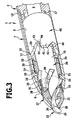
- FIGS. 6 to 14 For the function of the arrangement described below is in particular the representations of FIGS. 6 to 14 Referenced.
- the entire arrangement is in a in FIG. 6 illustrated starting position, in which the protective cap 27 are in its retracted rest position and the knife carrier 20 in its retracted protective position.
- the teeth 34 of the protective cap 27 are out of engagement with the teeth 42 of the sleeve-shaped switching element 40.
- the cutting edge 23 of the blade 22 is in the region in which the protective cap 27 projects beyond the end cap 7, completely withdrawn into the interior of the protective cap 27, so that the cutting edge 23 outside the end cap 7 does not project beyond the protective cap 27.
- the obturator For the use of the obturator, it is first necessary to activate the knife, this is done by pushing on the push button 5 and thus by advancing the push rod 6 and the fixedly connected knife carrier 20. This is advanced against the action of the coil spring 36 and thereby also slightly rotated by the leadership of the helical cutting edge 23 in the guide 25.
- the front cam 46 thereby moves on a path that is oblique to the longitudinal direction of the housing 2, in the FIGS. 6 and 14 this path is indicated in each case by the arrow B. During this displacement, the front cams 46 slide along the first portion 48 of the cam track 45, thereby rotating the sleeve-shaped switching element 40 in the direction of arrows C in the FIGS. 7 and 12 in a first direction.
- the cam track 45 is thus at this rotation in the representation of FIGS. 7 and 12 moved up.
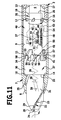
- the front cams 46 reach from the rear end of the first section 48 (solid contour in FIG. 12 ) to the front end of the first section 48 (dotted contour in FIG FIG. 12 ), and then they are advanced even further into an end position (dashed outline in FIG FIG. 12 ). This further displacement takes place for the front cam 46 without contact with the cam track 45, ie, the front cam 46 rotate the switching element 40 only during their investment on the first section 48th
- the arrangement of the front cams 46 and the rear cams 47 is selected so that the rear cams 47 engage the second portion 49 as soon as the front cams 46 have left the first portion 48.
- the rear cams 47 are also displaced on an inclined path to the longitudinal axis, which also corresponds to the direction of the arrows B. Since the second portion 49 stronger relative to the longitudinal direction of the housing 2 is inclined as this direction of movement of the rear cams 47 indicated by the arrow B, the rear cams 47 abut against the second section 49 and, as the knife carrier 20 is further displaced, rotate the switching element 40 counter to the first direction in a second direction is in FIG. 12 also indicated by the arrow C.
- the advancing movement of the knife carrier 20 is limited by a stop, not shown in the drawing, for example, this stop may be provided on the push button 5. If the user lets go of the push button after reaching this foremost point, the knife carrier 20 is pushed back under the action of the coil spring 36, in the same way indicated by the arrow B way. In this case, the front cams 46 hit the third section of the cam track 45, since the cam track has been rotated by the rear cam 47 in the second direction and is now in the displacement path of the front cams 46 with the third section 50 ( FIG. 13 ). The return movement of the knife carrier 20 is thus blocked by the abutment of the front cam 46 on the third portion 50 of the cam track 45.
- the surgeon When piercing, the surgeon places the tip 24 of the knife 22 on the body wall and advances the obturator with simultaneous rotation towards the body wall so that the knife 22 penetrates along the cutting edge 23 into the body wall.
- the front end 28 of the cap 27 applies to the body wall and is from this against the action of the coil spring 36 at the same time Twist pushed by the leadership of the helical cutting edge 23 in the end cap 7 ( Figures 9 and 13 ).
- the teeth 34 of the protective cap 27 dip between the teeth 42 of the switching element 40 and lie against one another with a very steep flank 56 or 57 which is only slightly inclined with respect to the longitudinal direction of the housing 2.
- the protective cap 27 with its tapering front end 28 and with the adjoining cylindrical region 31 passes through the opening introduced into the body wall and no longer sufficiently strong against the action of the helical spring 36 is inserted into the end cap 7, but the cap 27 can now be moved under the action of the coil spring 36 forward again to its rest position until the annular step 32 of the shaft-shaped extension 30 abuts the projection 14.
- the teeth 34 of the protective cap 27 come out of engagement with the teeth 42, that is, the switching element 40 is thereby released and can now rotate freely again. Under the action of the coil spring 36, therefore, now the knife carrier 20 is pushed back into its protective position, since the switching element 40 does not block this return movement.
- the switching element 40 is simultaneously rotated in the second direction, since the front cam 46 along the fifth section 52 along (dashed contour in FIG. 14 ) until the in FIG. 6 shown initial position is reached, in which the knife carrier 20 is fully retracted and in which the cutting edge 23 is completely overlapped in the lying outside of the end cap 7 part of the protective cap 27.
- the structure of the arrangement described is very simple, since only three movable parts and a coil spring must be used in the tubular housing, and the assembly is very simple, since it is sufficient to assemble these parts concentrically and the end cap then firmly with the subsequent shaft-shaped part connect the tubular housing. In the same way, a separation and thus a cleaning can take place.
- the entire arrangement is to be accommodated in the knife-near front part of the tubular housing, without thereby the outer diameter must be increased, so that no parts of the retraction device must be arranged in the grip area of the obturator 1 with the exception of the push button 5.
Landscapes
- Health & Medical Sciences (AREA)
- Surgery (AREA)
- Life Sciences & Earth Sciences (AREA)
- Medical Informatics (AREA)
- Nuclear Medicine, Radiotherapy & Molecular Imaging (AREA)
- Engineering & Computer Science (AREA)
- Biomedical Technology (AREA)
- Heart & Thoracic Surgery (AREA)
- Pathology (AREA)
- Molecular Biology (AREA)
- Animal Behavior & Ethology (AREA)
- General Health & Medical Sciences (AREA)
- Public Health (AREA)
- Veterinary Medicine (AREA)
- Surgical Instruments (AREA)
- Materials For Medical Uses (AREA)
Applications Claiming Priority (2)
| Application Number | Priority Date | Filing Date | Title |
|---|---|---|---|
| DE102006059012A DE102006059012B3 (de) | 2006-12-14 | 2006-12-14 | Chirurgischer Obturator |
| EP07819347A EP2088943B1 (fr) | 2006-12-14 | 2007-10-26 | Obturateur chirurgical |
Related Parent Applications (2)
| Application Number | Title | Priority Date | Filing Date |
|---|---|---|---|
| EP07819347.1 Division | 2007-10-26 | ||
| EP07819347A Division EP2088943B1 (fr) | 2006-12-14 | 2007-10-26 | Obturateur chirurgical |
Publications (2)
| Publication Number | Publication Date |
|---|---|
| EP2100564A1 true EP2100564A1 (fr) | 2009-09-16 |
| EP2100564B1 EP2100564B1 (fr) | 2010-12-22 |
Family
ID=39103004
Family Applications (2)
| Application Number | Title | Priority Date | Filing Date |
|---|---|---|---|
| EP07819347A Not-in-force EP2088943B1 (fr) | 2006-12-14 | 2007-10-26 | Obturateur chirurgical |
| EP09161399A Not-in-force EP2100564B1 (fr) | 2006-12-14 | 2007-10-26 | Obturateur chirurgical |
Family Applications Before (1)
| Application Number | Title | Priority Date | Filing Date |
|---|---|---|---|
| EP07819347A Not-in-force EP2088943B1 (fr) | 2006-12-14 | 2007-10-26 | Obturateur chirurgical |
Country Status (7)
| Country | Link |
|---|---|
| US (1) | US8105348B2 (fr) |
| EP (2) | EP2088943B1 (fr) |
| JP (1) | JP5146459B2 (fr) |
| AT (2) | ATE476926T1 (fr) |
| DE (2) | DE102006059012B3 (fr) |
| ES (2) | ES2355287T3 (fr) |
| WO (1) | WO2008071257A1 (fr) |
Families Citing this family (2)
| Publication number | Priority date | Publication date | Assignee | Title |
|---|---|---|---|---|
| US9358365B2 (en) * | 2010-07-30 | 2016-06-07 | Boston Scientific Scimed, Inc. | Precision electrode movement control for renal nerve ablation |
| US9186173B2 (en) * | 2012-04-27 | 2015-11-17 | Specialty Care, Inc. | Optical obturator system |
Citations (8)
| Publication number | Priority date | Publication date | Assignee | Title |
|---|---|---|---|---|
| EP0495633A1 (fr) * | 1991-01-15 | 1992-07-22 | Ethicon, Inc. | Lame pour un trocart chirurgical |
| US5346459A (en) * | 1993-04-14 | 1994-09-13 | Minnesota Mining And Manufacturing Company | Trocar |
| US5360405A (en) * | 1991-11-27 | 1994-11-01 | Inbae Yoon | Automatic retractable safety penetrating instrument |
| US5462532A (en) | 1993-03-17 | 1995-10-31 | Origin Medsystems, Inc. | Trocar with safety sensing sleeve |
| EP0499457B1 (fr) | 1991-02-15 | 1997-05-14 | Origin Medsystems, Inc. | Trocart |
| EP0705077B1 (fr) | 1993-05-28 | 1998-04-08 | Origin Medsystems, Inc. | Trocart a embout retracteur pourvu de pistons detecteurs |
| EP0600921B1 (fr) | 1991-08-30 | 1998-05-27 | Origin Medsystems, Inc. | Trocart a pointe retractable |
| DE202006008405U1 (de) | 2006-05-27 | 2006-07-27 | Aesculap Ag & Co. Kg | Chirurgischer Obturator |
Family Cites Families (22)
| Publication number | Priority date | Publication date | Assignee | Title |
|---|---|---|---|---|
| US3051132A (en) * | 1959-09-21 | 1962-08-28 | Frank Theodore Johmann | Protraction-retraction mechanism for writing instruments |
| US4601710B1 (en) | 1983-08-24 | 1998-05-05 | United States Surgical Corp | Trocar assembly |
| WO1989003661A1 (fr) | 1987-10-26 | 1989-05-05 | Endotherapeutics | Trocart avec verrou ameliore |
| GB8816033D0 (en) | 1988-07-06 | 1988-08-10 | Ethicon Inc | Improved safety trocar |
| US5215526A (en) * | 1988-07-06 | 1993-06-01 | Ethicon, Inc. | Safety trocar |
| US5645556A (en) | 1990-12-18 | 1997-07-08 | Yoon; Inbae | Safety penetrating instrument with triggered penetrating member retraction and single or multiple safety member protrusion |
| US5324268A (en) | 1991-12-16 | 1994-06-28 | Inbae Yoon | Trocar with safety shield |
| US5645076A (en) | 1991-08-14 | 1997-07-08 | Yoon; Inbae | Automatic retractable safety penetrating instrument |
| US5330432A (en) | 1991-12-06 | 1994-07-19 | Inbae Yoon | Retractable safety penetrating instrument |
| US5779680A (en) | 1991-11-27 | 1998-07-14 | Yoon; Inbae | Retractable safety needle instrument with movable safety member |
| US5569289A (en) | 1993-06-24 | 1996-10-29 | Yoon; Inbae | Safety penetrating instrument with penetrating member and cannula moving during penetration and triggered safety member protusion |
| US5591191A (en) | 1994-01-26 | 1997-01-07 | Kieturakis; Maciej J. | Surgical instrument and method for helically incising a pathway into the interior of the body |
| DE4411685C2 (de) | 1994-04-05 | 1996-10-02 | Helmut Dipl Ing Wurster | Trokardorn |
| US5662673A (en) | 1995-04-05 | 1997-09-02 | Kieturakis; Maciej J. | Surgical trocar and method for placing a trocar sleeve in a body wall |
| US5609604A (en) | 1995-10-16 | 1997-03-11 | Ethicon Endo-Surgery, Inc. | Trocar with improved blade attachment |
| US5755697A (en) | 1995-11-22 | 1998-05-26 | Jones; Calvin E. | Self-tunneling, self-securing percutaneous catheterization device and method of use thereof |
| US5674237A (en) * | 1996-03-06 | 1997-10-07 | Ott; Henryk | Safety trocar |
| DE19718086C2 (de) | 1997-04-29 | 2001-07-05 | Florian Krug | Trokar als Zugangsinstrument für die minimalinvasive Chirurgie |
| US6830578B2 (en) | 2001-11-26 | 2004-12-14 | Neosurg Technologies, Inc. | Trocar |
| DE202006008406U1 (de) | 2006-05-27 | 2006-07-27 | Aesculap Ag & Co. Kg | Chirurgischer Obturator |
| DE102006024757A1 (de) | 2006-05-27 | 2007-12-06 | Aesculap Ag & Co. Kg | Chirurgischer Obturator |
| DE202006018883U1 (de) * | 2006-12-14 | 2007-02-15 | Aesculap Ag & Co. Kg | Chirurgischer Obturator |
-
2006
- 2006-12-14 DE DE102006059012A patent/DE102006059012B3/de not_active Expired - Fee Related
-
2007
- 2007-10-26 ES ES09161399T patent/ES2355287T3/es active Active
- 2007-10-26 ES ES07819347T patent/ES2348105T3/es active Active
- 2007-10-26 EP EP07819347A patent/EP2088943B1/fr not_active Not-in-force
- 2007-10-26 AT AT07819347T patent/ATE476926T1/de active
- 2007-10-26 DE DE502007006060T patent/DE502007006060D1/de active Active
- 2007-10-26 EP EP09161399A patent/EP2100564B1/fr not_active Not-in-force
- 2007-10-26 JP JP2009540609A patent/JP5146459B2/ja not_active Expired - Fee Related
- 2007-10-26 WO PCT/EP2007/009299 patent/WO2008071257A1/fr not_active Ceased
- 2007-10-26 AT AT09161399T patent/ATE492226T1/de active
-
2009
- 2009-06-03 US US12/455,680 patent/US8105348B2/en not_active Expired - Fee Related
Patent Citations (8)
| Publication number | Priority date | Publication date | Assignee | Title |
|---|---|---|---|---|
| EP0495633A1 (fr) * | 1991-01-15 | 1992-07-22 | Ethicon, Inc. | Lame pour un trocart chirurgical |
| EP0499457B1 (fr) | 1991-02-15 | 1997-05-14 | Origin Medsystems, Inc. | Trocart |
| EP0600921B1 (fr) | 1991-08-30 | 1998-05-27 | Origin Medsystems, Inc. | Trocart a pointe retractable |
| US5360405A (en) * | 1991-11-27 | 1994-11-01 | Inbae Yoon | Automatic retractable safety penetrating instrument |
| US5462532A (en) | 1993-03-17 | 1995-10-31 | Origin Medsystems, Inc. | Trocar with safety sensing sleeve |
| US5346459A (en) * | 1993-04-14 | 1994-09-13 | Minnesota Mining And Manufacturing Company | Trocar |
| EP0705077B1 (fr) | 1993-05-28 | 1998-04-08 | Origin Medsystems, Inc. | Trocart a embout retracteur pourvu de pistons detecteurs |
| DE202006008405U1 (de) | 2006-05-27 | 2006-07-27 | Aesculap Ag & Co. Kg | Chirurgischer Obturator |
Also Published As
| Publication number | Publication date |
|---|---|
| DE102006059012B3 (de) | 2008-05-29 |
| EP2088943A1 (fr) | 2009-08-19 |
| EP2100564B1 (fr) | 2010-12-22 |
| ATE476926T1 (de) | 2010-08-15 |
| DE502007006060D1 (de) | 2011-02-03 |
| US8105348B2 (en) | 2012-01-31 |
| EP2088943B1 (fr) | 2010-08-11 |
| JP5146459B2 (ja) | 2013-02-20 |
| ES2355287T3 (es) | 2011-03-24 |
| US20090306698A1 (en) | 2009-12-10 |
| ES2348105T3 (es) | 2010-11-30 |
| JP2010512201A (ja) | 2010-04-22 |
| ATE492226T1 (de) | 2011-01-15 |
| WO2008071257A1 (fr) | 2008-06-19 |
Similar Documents
| Publication | Publication Date | Title |
|---|---|---|
| DE202006018883U1 (de) | Chirurgischer Obturator | |
| EP2023831B1 (fr) | Obturateur chirurgical | |
| DE69531417T2 (de) | Vorrichtung für kreisformige Anastomose | |
| EP1180381B1 (fr) | Cathéter intraveineux muni d'une gaine de protection | |
| EP2739329B2 (fr) | Système de sécurité pour dispositifs d'injection | |
| EP3528688B1 (fr) | Dispositif médical | |
| EP1745855A2 (fr) | Distributeur, notamment pour pulvériser un produit fluide contenu dans un réservoir | |
| DE1957833A1 (de) | Injektionsspritze,insbesondere von dem Patienten selbst gehandhabte Injektionsspritze | |
| DE2711124B1 (de) | Handpipette | |
| EP3338960B1 (fr) | Machine-outil portative | |
| EP0697198B1 (fr) | Applicateur de pinces chirurgicales | |
| EP2100564B1 (fr) | Obturateur chirurgical | |
| DE102009049317B4 (de) | Chirurgisches Instrument | |
| DE102011014200B4 (de) | Stechhilfe mit seitlich angebrachtem Betätigungselement | |
| DE102009022199B4 (de) | Werkzeugaufnahme | |
| EP1329338A2 (fr) | Instrument d'écriture | |
| WO2008012185A1 (fr) | Coupe-tubes | |
| DE102012112882B4 (de) | Stechhilfe zur Gewinnung von Körperflüssigkeitsproben | |
| DE102016120158A1 (de) | Vorrichtung zum Öffnen und Spalten von Kokosnüssen | |
| DE9413296U1 (de) | Chirurgisches Anlegegerät für Clipse | |
| DE112022006345T5 (de) | Biopsiepistole | |
| DE4429744A1 (de) | Chirurgischer Sicherheitstrokar | |
| DE19740847C1 (de) | Chirurgisches Instrument zum öffnen eines Gefässclips | |
| EP2787137A1 (fr) | Dispositif de verrouillage | |
| DE202006008405U1 (de) | Chirurgischer Obturator |
Legal Events
| Date | Code | Title | Description |
|---|---|---|---|
| PUAI | Public reference made under article 153(3) epc to a published international application that has entered the european phase |
Free format text: ORIGINAL CODE: 0009012 |
|
| AC | Divisional application: reference to earlier application |
Ref document number: 2088943 Country of ref document: EP Kind code of ref document: P |
|
| AK | Designated contracting states |
Kind code of ref document: A1 Designated state(s): AT BE BG CH CY CZ DE DK EE ES FI FR GB GR HU IE IS IT LI LT LU LV MC MT NL PL PT RO SE SI SK TR |
|
| 17P | Request for examination filed |
Effective date: 20091030 |
|
| GRAP | Despatch of communication of intention to grant a patent |
Free format text: ORIGINAL CODE: EPIDOSNIGR1 |
|
| GRAS | Grant fee paid |
Free format text: ORIGINAL CODE: EPIDOSNIGR3 |
|
| GRAA | (expected) grant |
Free format text: ORIGINAL CODE: 0009210 |
|
| AC | Divisional application: reference to earlier application |
Ref document number: 2088943 Country of ref document: EP Kind code of ref document: P |
|
| AK | Designated contracting states |
Kind code of ref document: B1 Designated state(s): AT BE BG CH CY CZ DE DK EE ES FI FR GB GR HU IE IS IT LI LT LU LV MC MT NL PL PT RO SE SI SK TR |
|
| REG | Reference to a national code |
Ref country code: GB Ref legal event code: FG4D Free format text: NOT ENGLISH |
|
| REG | Reference to a national code |
Ref country code: CH Ref legal event code: EP |
|
| REG | Reference to a national code |
Ref country code: IE Ref legal event code: FG4D |
|
| REF | Corresponds to: |
Ref document number: 502007006060 Country of ref document: DE Date of ref document: 20110203 Kind code of ref document: P |
|
| REG | Reference to a national code |
Ref country code: DE Ref legal event code: R096 Ref document number: 502007006060 Country of ref document: DE Effective date: 20110203 |
|
| REG | Reference to a national code |
Ref country code: ES Ref legal event code: FG2A Ref document number: 2355287 Country of ref document: ES Kind code of ref document: T3 Effective date: 20110324 |
|
| REG | Reference to a national code |
Ref country code: NL Ref legal event code: VDEP Effective date: 20101222 |
|
| PG25 | Lapsed in a contracting state [announced via postgrant information from national office to epo] |
Ref country code: LT Free format text: LAPSE BECAUSE OF FAILURE TO SUBMIT A TRANSLATION OF THE DESCRIPTION OR TO PAY THE FEE WITHIN THE PRESCRIBED TIME-LIMIT Effective date: 20101222 |
|
| LTIE | Lt: invalidation of european patent or patent extension |
Effective date: 20101222 |
|
| PG25 | Lapsed in a contracting state [announced via postgrant information from national office to epo] |
Ref country code: CY Free format text: LAPSE BECAUSE OF FAILURE TO SUBMIT A TRANSLATION OF THE DESCRIPTION OR TO PAY THE FEE WITHIN THE PRESCRIBED TIME-LIMIT Effective date: 20101222 Ref country code: LV Free format text: LAPSE BECAUSE OF FAILURE TO SUBMIT A TRANSLATION OF THE DESCRIPTION OR TO PAY THE FEE WITHIN THE PRESCRIBED TIME-LIMIT Effective date: 20101222 Ref country code: SE Free format text: LAPSE BECAUSE OF FAILURE TO SUBMIT A TRANSLATION OF THE DESCRIPTION OR TO PAY THE FEE WITHIN THE PRESCRIBED TIME-LIMIT Effective date: 20101222 Ref country code: SI Free format text: LAPSE BECAUSE OF FAILURE TO SUBMIT A TRANSLATION OF THE DESCRIPTION OR TO PAY THE FEE WITHIN THE PRESCRIBED TIME-LIMIT Effective date: 20101222 Ref country code: FI Free format text: LAPSE BECAUSE OF FAILURE TO SUBMIT A TRANSLATION OF THE DESCRIPTION OR TO PAY THE FEE WITHIN THE PRESCRIBED TIME-LIMIT Effective date: 20101222 Ref country code: BG Free format text: LAPSE BECAUSE OF FAILURE TO SUBMIT A TRANSLATION OF THE DESCRIPTION OR TO PAY THE FEE WITHIN THE PRESCRIBED TIME-LIMIT Effective date: 20110322 |
|
| REG | Reference to a national code |
Ref country code: IE Ref legal event code: FD4D |
|
| PG25 | Lapsed in a contracting state [announced via postgrant information from national office to epo] |
Ref country code: IS Free format text: LAPSE BECAUSE OF FAILURE TO SUBMIT A TRANSLATION OF THE DESCRIPTION OR TO PAY THE FEE WITHIN THE PRESCRIBED TIME-LIMIT Effective date: 20110422 Ref country code: PT Free format text: LAPSE BECAUSE OF FAILURE TO SUBMIT A TRANSLATION OF THE DESCRIPTION OR TO PAY THE FEE WITHIN THE PRESCRIBED TIME-LIMIT Effective date: 20110422 Ref country code: GR Free format text: LAPSE BECAUSE OF FAILURE TO SUBMIT A TRANSLATION OF THE DESCRIPTION OR TO PAY THE FEE WITHIN THE PRESCRIBED TIME-LIMIT Effective date: 20110323 Ref country code: EE Free format text: LAPSE BECAUSE OF FAILURE TO SUBMIT A TRANSLATION OF THE DESCRIPTION OR TO PAY THE FEE WITHIN THE PRESCRIBED TIME-LIMIT Effective date: 20101222 Ref country code: CZ Free format text: LAPSE BECAUSE OF FAILURE TO SUBMIT A TRANSLATION OF THE DESCRIPTION OR TO PAY THE FEE WITHIN THE PRESCRIBED TIME-LIMIT Effective date: 20101222 |
|
| PG25 | Lapsed in a contracting state [announced via postgrant information from national office to epo] |
Ref country code: NL Free format text: LAPSE BECAUSE OF FAILURE TO SUBMIT A TRANSLATION OF THE DESCRIPTION OR TO PAY THE FEE WITHIN THE PRESCRIBED TIME-LIMIT Effective date: 20101222 Ref country code: SK Free format text: LAPSE BECAUSE OF FAILURE TO SUBMIT A TRANSLATION OF THE DESCRIPTION OR TO PAY THE FEE WITHIN THE PRESCRIBED TIME-LIMIT Effective date: 20101222 Ref country code: RO Free format text: LAPSE BECAUSE OF FAILURE TO SUBMIT A TRANSLATION OF THE DESCRIPTION OR TO PAY THE FEE WITHIN THE PRESCRIBED TIME-LIMIT Effective date: 20101222 Ref country code: PL Free format text: LAPSE BECAUSE OF FAILURE TO SUBMIT A TRANSLATION OF THE DESCRIPTION OR TO PAY THE FEE WITHIN THE PRESCRIBED TIME-LIMIT Effective date: 20101222 |
|
| PLBE | No opposition filed within time limit |
Free format text: ORIGINAL CODE: 0009261 |
|
| STAA | Information on the status of an ep patent application or granted ep patent |
Free format text: STATUS: NO OPPOSITION FILED WITHIN TIME LIMIT |
|
| PG25 | Lapsed in a contracting state [announced via postgrant information from national office to epo] |
Ref country code: IE Free format text: LAPSE BECAUSE OF FAILURE TO SUBMIT A TRANSLATION OF THE DESCRIPTION OR TO PAY THE FEE WITHIN THE PRESCRIBED TIME-LIMIT Effective date: 20101222 Ref country code: DK Free format text: LAPSE BECAUSE OF FAILURE TO SUBMIT A TRANSLATION OF THE DESCRIPTION OR TO PAY THE FEE WITHIN THE PRESCRIBED TIME-LIMIT Effective date: 20101222 |
|
| 26N | No opposition filed |
Effective date: 20110923 |
|
| REG | Reference to a national code |
Ref country code: DE Ref legal event code: R097 Ref document number: 502007006060 Country of ref document: DE Effective date: 20110923 |
|
| BERE | Be: lapsed |
Owner name: AESCULAP A.G. Effective date: 20111031 |
|
| PG25 | Lapsed in a contracting state [announced via postgrant information from national office to epo] |
Ref country code: MC Free format text: LAPSE BECAUSE OF NON-PAYMENT OF DUE FEES Effective date: 20111031 |
|
| REG | Reference to a national code |
Ref country code: CH Ref legal event code: PL |
|
| PG25 | Lapsed in a contracting state [announced via postgrant information from national office to epo] |
Ref country code: LI Free format text: LAPSE BECAUSE OF NON-PAYMENT OF DUE FEES Effective date: 20111031 Ref country code: CH Free format text: LAPSE BECAUSE OF NON-PAYMENT OF DUE FEES Effective date: 20111031 Ref country code: BE Free format text: LAPSE BECAUSE OF NON-PAYMENT OF DUE FEES Effective date: 20111031 |
|
| PG25 | Lapsed in a contracting state [announced via postgrant information from national office to epo] |
Ref country code: MT Free format text: LAPSE BECAUSE OF FAILURE TO SUBMIT A TRANSLATION OF THE DESCRIPTION OR TO PAY THE FEE WITHIN THE PRESCRIBED TIME-LIMIT Effective date: 20101222 |
|
| PG25 | Lapsed in a contracting state [announced via postgrant information from national office to epo] |
Ref country code: LU Free format text: LAPSE BECAUSE OF NON-PAYMENT OF DUE FEES Effective date: 20111026 |
|
| PG25 | Lapsed in a contracting state [announced via postgrant information from national office to epo] |
Ref country code: TR Free format text: LAPSE BECAUSE OF FAILURE TO SUBMIT A TRANSLATION OF THE DESCRIPTION OR TO PAY THE FEE WITHIN THE PRESCRIBED TIME-LIMIT Effective date: 20101222 |
|
| PG25 | Lapsed in a contracting state [announced via postgrant information from national office to epo] |
Ref country code: HU Free format text: LAPSE BECAUSE OF FAILURE TO SUBMIT A TRANSLATION OF THE DESCRIPTION OR TO PAY THE FEE WITHIN THE PRESCRIBED TIME-LIMIT Effective date: 20101222 |
|
| REG | Reference to a national code |
Ref country code: AT Ref legal event code: MM01 Ref document number: 492226 Country of ref document: AT Kind code of ref document: T Effective date: 20121031 |
|
| PG25 | Lapsed in a contracting state [announced via postgrant information from national office to epo] |
Ref country code: AT Free format text: LAPSE BECAUSE OF NON-PAYMENT OF DUE FEES Effective date: 20121031 |
|
| REG | Reference to a national code |
Ref country code: DE Ref legal event code: R082 Ref document number: 502007006060 Country of ref document: DE Representative=s name: HOEGER, STELLRECHT & PARTNER PATENTANWAELTE MB, DE |
|
| REG | Reference to a national code |
Ref country code: FR Ref legal event code: PLFP Year of fee payment: 9 |
|
| REG | Reference to a national code |
Ref country code: FR Ref legal event code: PLFP Year of fee payment: 10 |
|
| REG | Reference to a national code |
Ref country code: FR Ref legal event code: PLFP Year of fee payment: 11 |
|
| REG | Reference to a national code |
Ref country code: FR Ref legal event code: PLFP Year of fee payment: 12 |
|
| REG | Reference to a national code |
Ref country code: DE Ref legal event code: R082 Ref document number: 502007006060 Country of ref document: DE Representative=s name: HOEGER, STELLRECHT & PARTNER PATENTANWAELTE MB, DE |
|
| PGFP | Annual fee paid to national office [announced via postgrant information from national office to epo] |
Ref country code: FR Payment date: 20201020 Year of fee payment: 14 Ref country code: GB Payment date: 20201022 Year of fee payment: 14 Ref country code: IT Payment date: 20201030 Year of fee payment: 14 Ref country code: ES Payment date: 20201117 Year of fee payment: 14 Ref country code: DE Payment date: 20201022 Year of fee payment: 14 |
|
| REG | Reference to a national code |
Ref country code: DE Ref legal event code: R119 Ref document number: 502007006060 Country of ref document: DE |
|
| GBPC | Gb: european patent ceased through non-payment of renewal fee |
Effective date: 20211026 |
|
| PG25 | Lapsed in a contracting state [announced via postgrant information from national office to epo] |
Ref country code: GB Free format text: LAPSE BECAUSE OF NON-PAYMENT OF DUE FEES Effective date: 20211026 Ref country code: DE Free format text: LAPSE BECAUSE OF NON-PAYMENT OF DUE FEES Effective date: 20220503 |
|
| PG25 | Lapsed in a contracting state [announced via postgrant information from national office to epo] |
Ref country code: FR Free format text: LAPSE BECAUSE OF NON-PAYMENT OF DUE FEES Effective date: 20211031 |
|
| PG25 | Lapsed in a contracting state [announced via postgrant information from national office to epo] |
Ref country code: IT Free format text: LAPSE BECAUSE OF NON-PAYMENT OF DUE FEES Effective date: 20211026 |
|
| REG | Reference to a national code |
Ref country code: ES Ref legal event code: FD2A Effective date: 20230210 |
|
| PG25 | Lapsed in a contracting state [announced via postgrant information from national office to epo] |
Ref country code: ES Free format text: LAPSE BECAUSE OF NON-PAYMENT OF DUE FEES Effective date: 20211027 |