EP2100675A1 - Appareil et procédé pour utilisation avec l'allumage des noyeaux - Google Patents
Appareil et procédé pour utilisation avec l'allumage des noyeaux Download PDFInfo
- Publication number
- EP2100675A1 EP2100675A1 EP08170487A EP08170487A EP2100675A1 EP 2100675 A1 EP2100675 A1 EP 2100675A1 EP 08170487 A EP08170487 A EP 08170487A EP 08170487 A EP08170487 A EP 08170487A EP 2100675 A1 EP2100675 A1 EP 2100675A1
- Authority
- EP
- European Patent Office
- Prior art keywords
- core
- saggar
- setter
- insert
- disposed
- Prior art date
- Legal status (The legal status is an assumption and is not a legal conclusion. Google has not performed a legal analysis and makes no representation as to the accuracy of the status listed.)
- Withdrawn
Links
- 238000010304 firing Methods 0.000 title claims abstract description 41
- 238000000034 method Methods 0.000 title claims abstract description 14
- 239000000919 ceramic Substances 0.000 claims abstract description 53
- 238000005266 casting Methods 0.000 claims abstract description 41
- 238000005245 sintering Methods 0.000 description 6
- 150000001875 compounds Chemical class 0.000 description 5
- PXHVJJICTQNCMI-UHFFFAOYSA-N Nickel Chemical compound [Ni] PXHVJJICTQNCMI-UHFFFAOYSA-N 0.000 description 4
- 239000011230 binding agent Substances 0.000 description 4
- 238000001816 cooling Methods 0.000 description 4
- 235000013312 flour Nutrition 0.000 description 4
- 239000002245 particle Substances 0.000 description 4
- 239000000654 additive Substances 0.000 description 3
- PNEYBMLMFCGWSK-UHFFFAOYSA-N aluminium oxide Inorganic materials [O-2].[O-2].[O-2].[Al+3].[Al+3] PNEYBMLMFCGWSK-UHFFFAOYSA-N 0.000 description 3
- 239000000463 material Substances 0.000 description 3
- 239000007769 metal material Substances 0.000 description 3
- VYPSYNLAJGMNEJ-UHFFFAOYSA-N Silicium dioxide Chemical compound O=[Si]=O VYPSYNLAJGMNEJ-UHFFFAOYSA-N 0.000 description 2
- MCMNRKCIXSYSNV-UHFFFAOYSA-N Zirconium dioxide Chemical compound O=[Zr]=O MCMNRKCIXSYSNV-UHFFFAOYSA-N 0.000 description 2
- 230000002411 adverse Effects 0.000 description 2
- 229910017052 cobalt Inorganic materials 0.000 description 2
- 239000010941 cobalt Substances 0.000 description 2
- GUTLYIVDDKVIGB-UHFFFAOYSA-N cobalt atom Chemical compound [Co] GUTLYIVDDKVIGB-UHFFFAOYSA-N 0.000 description 2
- 230000000295 complement effect Effects 0.000 description 2
- KZHJGOXRZJKJNY-UHFFFAOYSA-N dioxosilane;oxo(oxoalumanyloxy)alumane Chemical compound O=[Si]=O.O=[Si]=O.O=[Al]O[Al]=O.O=[Al]O[Al]=O.O=[Al]O[Al]=O KZHJGOXRZJKJNY-UHFFFAOYSA-N 0.000 description 2
- 238000002347 injection Methods 0.000 description 2
- 239000007924 injection Substances 0.000 description 2
- 239000007788 liquid Substances 0.000 description 2
- 238000004519 manufacturing process Methods 0.000 description 2
- 239000002184 metal Substances 0.000 description 2
- 229910052751 metal Inorganic materials 0.000 description 2
- 239000000203 mixture Substances 0.000 description 2
- 238000000465 moulding Methods 0.000 description 2
- 229910052863 mullite Inorganic materials 0.000 description 2
- 229910052759 nickel Inorganic materials 0.000 description 2
- 239000011819 refractory material Substances 0.000 description 2
- 229910000601 superalloy Inorganic materials 0.000 description 2
- LFQSCWFLJHTTHZ-UHFFFAOYSA-N Ethanol Chemical compound CCO LFQSCWFLJHTTHZ-UHFFFAOYSA-N 0.000 description 1
- BOTDANWDWHJENH-UHFFFAOYSA-N Tetraethyl orthosilicate Chemical compound CCO[Si](OCC)(OCC)OCC BOTDANWDWHJENH-UHFFFAOYSA-N 0.000 description 1
- 229910010293 ceramic material Inorganic materials 0.000 description 1
- 239000000470 constituent Substances 0.000 description 1
- 238000001746 injection moulding Methods 0.000 description 1
- 238000002955 isolation Methods 0.000 description 1
- 238000002156 mixing Methods 0.000 description 1
- 239000000377 silicon dioxide Substances 0.000 description 1
- 238000001721 transfer moulding Methods 0.000 description 1
- 229910052845 zircon Inorganic materials 0.000 description 1
- GFQYVLUOOAAOGM-UHFFFAOYSA-N zirconium(iv) silicate Chemical compound [Zr+4].[O-][Si]([O-])([O-])[O-] GFQYVLUOOAAOGM-UHFFFAOYSA-N 0.000 description 1
Images

Classifications
-
- C—CHEMISTRY; METALLURGY
- C04—CEMENTS; CONCRETE; ARTIFICIAL STONE; CERAMICS; REFRACTORIES
- C04B—LIME, MAGNESIA; SLAG; CEMENTS; COMPOSITIONS THEREOF, e.g. MORTARS, CONCRETE OR LIKE BUILDING MATERIALS; ARTIFICIAL STONE; CERAMICS; REFRACTORIES; TREATMENT OF NATURAL STONE
- C04B35/00—Shaped ceramic products characterised by their composition; Ceramics compositions; Processing powders of inorganic compounds preparatory to the manufacturing of ceramic products
- C04B35/622—Forming processes; Processing powders of inorganic compounds preparatory to the manufacturing of ceramic products
- C04B35/64—Burning or sintering processes
-
- B—PERFORMING OPERATIONS; TRANSPORTING
- B22—CASTING; POWDER METALLURGY
- B22C—FOUNDRY MOULDING
- B22C9/00—Moulds or cores; Moulding processes
- B22C9/10—Cores; Manufacture or installation of cores
- B22C9/101—Permanent cores
-
- B—PERFORMING OPERATIONS; TRANSPORTING
- B22—CASTING; POWDER METALLURGY
- B22C—FOUNDRY MOULDING
- B22C9/00—Moulds or cores; Moulding processes
- B22C9/12—Treating moulds or cores, e.g. drying, hardening
-
- F—MECHANICAL ENGINEERING; LIGHTING; HEATING; WEAPONS; BLASTING
- F27—FURNACES; KILNS; OVENS; RETORTS
- F27D—DETAILS OR ACCESSORIES OF FURNACES, KILNS, OVENS OR RETORTS, IN SO FAR AS THEY ARE OF KINDS OCCURRING IN MORE THAN ONE KIND OF FURNACE
- F27D5/00—Supports, screens or the like for the charge within the furnace
- F27D5/0006—Composite supporting structures
- F27D5/0012—Modules of the sagger or setter type; Supports built up from them
-
- F—MECHANICAL ENGINEERING; LIGHTING; HEATING; WEAPONS; BLASTING
- F27—FURNACES; KILNS; OVENS; RETORTS
- F27D—DETAILS OR ACCESSORIES OF FURNACES, KILNS, OVENS OR RETORTS, IN SO FAR AS THEY ARE OF KINDS OCCURRING IN MORE THAN ONE KIND OF FURNACE
- F27D5/00—Supports, screens or the like for the charge within the furnace
- F27D5/0068—Containers
Definitions
- the present invention relates to the firing (sintering) of one or more ceramic cores used for the casting of molten metallic materials.
- the ceramic core is typically made using a plasticized ceramic compound comprising ceramic flour, binder and various additives.
- the ceramic compound is injection molded, transfer molded or poured at elevated temperature in a core die or mold.
- the green (unfired) core is removed from the die or mold, it typically is placed on a rigid ceramic setter to cool to ambient temperature before core finishing and gauging operations and firing at an elevated sintering temperature.
- the green ceramic core is fired on the ceramic core setter at elevated (superambient) temperature in one or more steps to sinter and strengthen the core for use in casting metallic material, such as a nickel base or cobalt base superalloy.
- U.S. Patent 6 403 020 discloses a green ceramic core positioned on a rigid core setter during firing.
- US Patents 5 014 763 and 6 347 660 disclose a green ceramic core positioned between top and bottom setters during firing.
- the rigid core setter is used during firing to maintain dimensional tolerances of the ceramic core since any setter contour distortion can adversely affect the dimensional tolerances achievable during firing of a ceramic core thereon.
- setter contour distortion may result in the green ceramic core having dimensional variations from one ceramic core to the next occur in a production run.
- multiple ceramic setters can be stacked atop one another in order to fire multiple ceramic cores concurrently.
- the ceramic setters can continually disort over time and the weight of each setter is magnified in the stack.
- the ceramic setters distort, core contour dimensional variations can occur.
- the present invention provides apparatus for use in firing a ceramic casting core wherein the apparatus includes a saggar and a core setter insert disposed in the saggar and having a core-receiving surface.
- the apparatus further includes a refractory particulate grog bed disposed on a bottom wall of the saggar wherein the core setter insert is disposed on the grog bed during firing (sintering).
- the apparatus further includes upstanding refractory supports disposed on a bottom wall of the saggar wherein the core setter insert is disposed on the supports during firing.
- the core-receiving surface has an airfoil shape.
- An airfoil-shaped core is disposed on the core-receiving surface for firing.
- the bottom wall of the saggar includes apertures for receiving core ejector pins.
- a method embodiment of the invention involves stacking multiple saggars, having core setter inserts/cores therein, atop one another and then firing the ceramic cores residing on the core setter inserts in the stacked setters.
- the saggars are stacked atop sidewalls of other saggars residing therebelow in the stack.
- Practice of the invention is advantageous to reduce core contour dimensional variations resulting from core setter distortion during firing, especially for thin complex airfoil-shaped cores used to cast hollow airfoil-shaped castings, such as turbine blades and vanes.
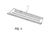
- the present invention is described herebelow for purposes of illustration with respect to apparatus/method for use firing a ceramic casting core C, Figure 6 , having an airfoil shape.
- Such ceramic casting cores are used in casting hollow airfoil castings, such as turbine blades and vanes, having one or more internal cooling passageways and are described in US Patents 5 014 763 and 6 347 660 , which are incorporated herein by reference.
- the ceramic casting core for use in casting a hollow airfoil casting can be made using a plasticized ceramic compound comprising ceramic flour, binder and various additives.
- the ceramic compound is injection molded, transfer molded or poured at elevated temperature in a core die or mold.
- the green (unfired) core When the green (unfired) core is removed from the die or mold, it typically is placed on a rigid ceramic setter to cool to ambient temperature before core finishing and gauging operations and firing at an elevated sintering temperature.
- the green ceramic core is fired on the ceramic setter at elevated (superambient) temperature in one or more steps to sinter and strengthen the core for use in casting metallic material, such as a nickel base or cobalt base superalloy for example.
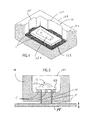
- An embodiment of the present invention provides apparatus for use in firing (sintering) a green, unfired ceramic casting core wherein the apparatus includes a refractory saggar 10 and a refractory core setter insert 12 disposed in the saggar as shown in Figures 1-4 for purposes of illustration and not limitation.
- the saggar 10 comprises a preformed fired, refractory box-like enclosure having sidewalls 10a and bottom wall 10b.
- the saggar typically is reusable and can be made of any suitable refractory material, such as a high temperature ceramic material including but not limited to mullite material, alumina-based material, and the like, that can withstand repeated firings over time and that can be fabricated to desired saggar shape.
- the dimensions of the saggar 10 are selected to form a saggar chamber 10c to receive the core setter insert 12 and the ceramic casting core thereon and yet render the saggar strong and durable enough for intended repeated use.
- the dimensions of the saggar chamber are selected in dependence on the size or sizes of various core setter inserts/casting cores to be fired.
- the chamber 10c will be capable of receiving various sizes of core setter inserts/casting cores to be fired for versatility in use of the saggar.
- the sidewalls 10a and bottom wall 10b can have a thickness of one (1) inch.
- the inner surfaces of the sidewalls 10a can be drafted as illustrated by dashed lines in Figure 2 . Also, the junction of the sidewalls 10a to bottom wall 10b can form a fillet joint as shown in Figure 2 .
- the sidewalls 10a can be provided with recesses 10r on their innser surfaces to provide access to remove the ceramic casting core after firing and/or airflow during firing of the core.
- the core setter insert 12 comprises a preformed fired, rigid ceramic setter having a core-receiving surface 12s.
- the surface 12s is shown having a partial airfoil shape for receiving ceramic casting core C having a complementary airfoil shape.
- the surface 12s has a preselected desired profile or contour complementary to a surface of the green ceramic casting core to be fired thereon.
- the core setter insert 12 includes a base 12b that is adapted to rest on refractory particulate grog bed 11 in one embodiment, Figure 4 , or on refractory supports 11' in another embodiment, Figure 5 .
- the core setter insert can be made by conventional poured molding technique where a plasticized ceramic compound is introduced into a die or mold (not shown), although the core setter insert can be made by other processes including, but not limited to, injection molding and transfer molding.
- Conventional poured setter molding involves mixing one or more ceramic flours (e.g.
- alumina, silica, zircon, and/or zirconia flour a liquid binder such as catalytically cured ethyl silicate liquid binder which contains a volatile alcohol constituent, and other additives, pouring the mixture in a mold or die having the shape of the core setter insert, curing the mixture, and and then removing the green core setter insert from the mold or die for firing.
- the core setter insert can be made with reduced thickness and outer periphery and less material (less mass) than otherwise used in the past as a result of isolation of the core setter insert from loads and distortion during firing in practice of the invention.
- the apparatus for use in firing the ceramic casting core includes the refractory particulate grog bed 11 residing on the bottom wall 10b of the saggar 10 and on which the core setter insert 12 is disposed and floats during firing.
- the grog bed 11 can comprise any suitable refractory material, such as high temperature ceramic particles including but not limited to coarse alumina particles, mullite particles, and the like, depending on core firing temperatures to be used, in the form of loose particles and of a bed thickness to help isolate the setter insert from loads and distortion during firing.
- the bed thickness can be from 1/4 to 1 inch, although other thicknesses can be used.
- the casting core can be removed manually by access through reccesses 10r using fingers or a suitable core removal tool, or core ejector mechanism.
- windows can be provided in the sidwalls 10a and/or bottom wall 10b to provide access to facilitate core removal.
- the apparatus in another illustrative embodiment of the invention shown in Figure 5 , includes upstanding refractory supports 11' such as pegs residing on the bottom wall 10b of the saggar wherein the core setter insert is disposed on the supports during firing.
- the bottom wall 10b can include apertures 10d through which ejector pins P of an injector plate P of a core ejector mechanism can extend to facilitate removal of the fired casting core from the saggar 10 after the saggar is removed from a firing furnace.
- the invention typically is practiced by firing (sintering) multiple ceramic casting cores concurrently for sake of high production and reduced costs, although a single ceramic casting core can be fired if desired.
- the temperature/time of firing will depend on the particular casting cores to be fired to provide desired fired core casting strength.
- the invention is not limited to any particular firing temperature/time. Firing temperatures can be in the realm of 3000 degrees F for some casting cores.
- a method embodiment of the invention involves stacking multiple saggars 10 (having the core setter inserts 12/casting cores therein) of the type described above atop one another and then firing the ceramic casting cores residing on the core setter inserts in the stacked setters.
- the saggars 10 are stacked atop sidewalls of other saggars residing therebelow in the stack.
- the top saggar is stacked so that its bottom wall 10b resides on the upwardly facing, sidewall surface 10s of the saggar next below it and so on down the stack of saggars.
- the lowermost saggar will have its bottom wall rest on a conventional refractory, ceramic or metallic support (not shown) such a high temperature ceramic or metallic plate.
- the weight of each saggar 10 is thereby placed on the sidewalls 10b of the saggar next below.
- Stacking of the saggars 10 in the manner described reduces loads on and distortion of the core setter inserts 12 during repeated firings and thus on the casting cores being fired to improve dimensional consistency of the fired casting cores.
- a bowed or twisted saggar can be reused in subsequent casting core firings without adverse affect on yield of acceptable casting cores.
- the core setter insert can be refaced after firing(s) if needed to maintain dimensional consistencies.
Landscapes
- Engineering & Computer Science (AREA)
- Chemical & Material Sciences (AREA)
- Mechanical Engineering (AREA)
- Manufacturing & Machinery (AREA)
- Ceramic Engineering (AREA)
- General Engineering & Computer Science (AREA)
- Inorganic Chemistry (AREA)
- Materials Engineering (AREA)
- Structural Engineering (AREA)
- Organic Chemistry (AREA)
- Molds, Cores, And Manufacturing Methods Thereof (AREA)
Applications Claiming Priority (1)
| Application Number | Priority Date | Filing Date | Title |
|---|---|---|---|
| US518207P | 2007-12-03 | 2007-12-03 |
Publications (1)
| Publication Number | Publication Date |
|---|---|
| EP2100675A1 true EP2100675A1 (fr) | 2009-09-16 |
Family
ID=40453260
Family Applications (1)
| Application Number | Title | Priority Date | Filing Date |
|---|---|---|---|
| EP08170487A Withdrawn EP2100675A1 (fr) | 2007-12-03 | 2008-12-02 | Appareil et procédé pour utilisation avec l'allumage des noyeaux |
Country Status (3)
| Country | Link |
|---|---|
| US (1) | US20120178040A1 (fr) |
| EP (1) | EP2100675A1 (fr) |
| JP (1) | JP2009136922A (fr) |
Cited By (1)
| Publication number | Priority date | Publication date | Assignee | Title |
|---|---|---|---|---|
| US9096472B2 (en) | 2012-09-12 | 2015-08-04 | General Electric Company | Methods of forming a ceramic component and a high temperature mold component for use therewith |
Families Citing this family (1)
| Publication number | Priority date | Publication date | Assignee | Title |
|---|---|---|---|---|
| DE202007008520U1 (de) * | 2007-02-21 | 2008-07-03 | Dekema Dental-Keramiköfen GmbH | Brenngutträger |
Citations (8)
| Publication number | Priority date | Publication date | Assignee | Title |
|---|---|---|---|---|
| FR428016A (fr) * | 1910-06-11 | 1911-08-21 | Leon Bernardaud | Cazettes pour la cuisson des plats et assiettes en porcelaine |
| US1448011A (en) * | 1922-02-06 | 1923-03-13 | Carborundum Co | Sagger structure |
| US5014763A (en) | 1988-11-30 | 1991-05-14 | Howmet Corporation | Method of making ceramic cores |
| JPH03177363A (ja) * | 1989-12-06 | 1991-08-01 | Matsushita Electric Ind Co Ltd | 半導体セラミックスの焼成方法 |
| JPH046165A (ja) * | 1990-04-23 | 1992-01-10 | Fujitsu General Ltd | 焼成方法 |
| US6347660B1 (en) | 1998-12-01 | 2002-02-19 | Howmet Research Corporation | Multipiece core assembly for cast airfoil |
| US6403020B1 (en) | 2001-08-07 | 2002-06-11 | Howmet Research Corporation | Method for firing ceramic cores |
| US20040159985A1 (en) * | 2003-02-18 | 2004-08-19 | Altoonian Mark A. | Method for making ceramic setter |
-
2008
- 2008-12-01 US US12/315,265 patent/US20120178040A1/en not_active Abandoned
- 2008-12-02 EP EP08170487A patent/EP2100675A1/fr not_active Withdrawn
- 2008-12-03 JP JP2008308778A patent/JP2009136922A/ja active Pending
Patent Citations (8)
| Publication number | Priority date | Publication date | Assignee | Title |
|---|---|---|---|---|
| FR428016A (fr) * | 1910-06-11 | 1911-08-21 | Leon Bernardaud | Cazettes pour la cuisson des plats et assiettes en porcelaine |
| US1448011A (en) * | 1922-02-06 | 1923-03-13 | Carborundum Co | Sagger structure |
| US5014763A (en) | 1988-11-30 | 1991-05-14 | Howmet Corporation | Method of making ceramic cores |
| JPH03177363A (ja) * | 1989-12-06 | 1991-08-01 | Matsushita Electric Ind Co Ltd | 半導体セラミックスの焼成方法 |
| JPH046165A (ja) * | 1990-04-23 | 1992-01-10 | Fujitsu General Ltd | 焼成方法 |
| US6347660B1 (en) | 1998-12-01 | 2002-02-19 | Howmet Research Corporation | Multipiece core assembly for cast airfoil |
| US6403020B1 (en) | 2001-08-07 | 2002-06-11 | Howmet Research Corporation | Method for firing ceramic cores |
| US20040159985A1 (en) * | 2003-02-18 | 2004-08-19 | Altoonian Mark A. | Method for making ceramic setter |
Cited By (1)
| Publication number | Priority date | Publication date | Assignee | Title |
|---|---|---|---|---|
| US9096472B2 (en) | 2012-09-12 | 2015-08-04 | General Electric Company | Methods of forming a ceramic component and a high temperature mold component for use therewith |
Also Published As
| Publication number | Publication date |
|---|---|
| JP2009136922A (ja) | 2009-06-25 |
| US20120178040A1 (en) | 2012-07-12 |
Similar Documents
| Publication | Publication Date | Title |
|---|---|---|
| US20040159985A1 (en) | Method for making ceramic setter | |
| EP1381481B1 (fr) | Noyau a parois multiples et procede | |
| EP1227905B1 (fr) | Ame de profil moule a plusieurs elements | |
| US6951239B1 (en) | Methods for manufacturing investment casting shells | |
| EP3429778B1 (fr) | Procédé de fabrication d'éléments caractéristiques perfectionnés dans un noyau pour la coulée | |
| US6186217B1 (en) | Multipiece core assembly | |
| US20060065383A1 (en) | Rapid prototype casting | |
| EP2316593A2 (fr) | Outillage de noyau fugitif et procédé | |
| EP1930098A1 (fr) | Noyaux en céramique, leurs procédés de fabrication et articles fabriqués avec ceux-ci | |
| EP0715913A1 (fr) | Noyaux en plusieurs parties pour la coulée à la cire perdue | |
| EP1992431A1 (fr) | Noyaux de moulage par coulée et procédés | |
| US6403020B1 (en) | Method for firing ceramic cores | |
| US6494250B1 (en) | Impregnated alumina-based core and method | |
| EP2100675A1 (fr) | Appareil et procédé pour utilisation avec l'allumage des noyeaux | |
| CN117620099A (zh) | 一种可控杂晶及反变形的空心涡轮叶片制造方法 | |
| EP3064331B1 (fr) | Procédé et apparaeil pour la cuisson de produits céramiques | |
| JP7644693B2 (ja) | 鋳型、その製造方法および鋳造方法 | |
| JPH0970642A (ja) | 鋳型の製造方法及びこの鋳型を用いた精密鋳造品の製造方法 | |
| EP3693100A1 (fr) | Procédé de chapelet de coulée de précision | |
| CN119282036B (zh) | 一种用于衡量空心叶片内腔扰流柱结构再结晶倾向的陶瓷型芯及其使用方法 | |
| JP7545476B2 (ja) | 板状焼成治具 | |
| JPH07241658A (ja) | 遠心鋳造用セラミック中子およびその製造方法 | |
| McCORMICK et al. | Evolution of the cast internally cooled gas turbine airfoil | |
| Nagabhushan et al. | Selection criteria for investment casting equipment |
Legal Events
| Date | Code | Title | Description |
|---|---|---|---|
| PUAI | Public reference made under article 153(3) epc to a published international application that has entered the european phase |
Free format text: ORIGINAL CODE: 0009012 |
|
| AK | Designated contracting states |
Kind code of ref document: A1 Designated state(s): AT BE BG CH CY CZ DE DK EE ES FI FR GB GR HR HU IE IS IT LI LT LU LV MC MT NL NO PL PT RO SE SI SK TR |
|
| AX | Request for extension of the european patent |
Extension state: AL BA MK RS |
|
| AKX | Designation fees paid | ||
| STAA | Information on the status of an ep patent application or granted ep patent |
Free format text: STATUS: THE APPLICATION IS DEEMED TO BE WITHDRAWN |
|
| 18D | Application deemed to be withdrawn |
Effective date: 20100317 |
|
| REG | Reference to a national code |
Ref country code: DE Ref legal event code: 8566 |