EP2100710A1 - Wärmedämmform, formkomponenten, formmaschine und verfahren zur herstellung der wärmedämmform - Google Patents
Wärmedämmform, formkomponenten, formmaschine und verfahren zur herstellung der wärmedämmform Download PDFInfo
- Publication number
- EP2100710A1 EP2100710A1 EP07859722A EP07859722A EP2100710A1 EP 2100710 A1 EP2100710 A1 EP 2100710A1 EP 07859722 A EP07859722 A EP 07859722A EP 07859722 A EP07859722 A EP 07859722A EP 2100710 A1 EP2100710 A1 EP 2100710A1
- Authority
- EP
- European Patent Office
- Prior art keywords
- heat
- mold
- insulating layer
- insulating
- transfer
- Prior art date
- Legal status (The legal status is an assumption and is not a legal conclusion. Google has not performed a legal analysis and makes no representation as to the accuracy of the status listed.)
- Withdrawn
Links
- 238000000465 moulding Methods 0.000 title claims abstract description 26
- 238000000034 method Methods 0.000 title claims description 22
- 238000004519 manufacturing process Methods 0.000 title claims description 4
- 238000012546 transfer Methods 0.000 claims abstract description 43
- 239000010410 layer Substances 0.000 claims description 90
- 238000005245 sintering Methods 0.000 claims description 28
- 239000000843 powder Substances 0.000 claims description 20
- 238000007747 plating Methods 0.000 claims description 18
- 239000011810 insulating material Substances 0.000 claims description 10
- 238000000280 densification Methods 0.000 claims description 5
- 239000002344 surface layer Substances 0.000 claims description 5
- 230000003746 surface roughness Effects 0.000 claims description 4
- 239000003795 chemical substances by application Substances 0.000 claims description 3
- 230000015572 biosynthetic process Effects 0.000 abstract description 15
- 230000003111 delayed effect Effects 0.000 abstract description 4
- 239000012778 molding material Substances 0.000 abstract description 3
- 239000011347 resin Substances 0.000 description 30
- 229920005989 resin Polymers 0.000 description 30
- 238000002347 injection Methods 0.000 description 18
- 239000007924 injection Substances 0.000 description 18
- 238000003825 pressing Methods 0.000 description 17
- 239000002131 composite material Substances 0.000 description 16
- 238000010438 heat treatment Methods 0.000 description 14
- MCMNRKCIXSYSNV-UHFFFAOYSA-N Zirconium dioxide Chemical compound O=[Zr]=O MCMNRKCIXSYSNV-UHFFFAOYSA-N 0.000 description 12
- 239000000919 ceramic Substances 0.000 description 11
- 229910010293 ceramic material Inorganic materials 0.000 description 11
- 238000001816 cooling Methods 0.000 description 11
- 230000007246 mechanism Effects 0.000 description 11
- PXHVJJICTQNCMI-UHFFFAOYSA-N Nickel Chemical compound [Ni] PXHVJJICTQNCMI-UHFFFAOYSA-N 0.000 description 10
- 230000007547 defect Effects 0.000 description 8
- 239000010419 fine particle Substances 0.000 description 8
- 239000011148 porous material Substances 0.000 description 8
- 238000005498 polishing Methods 0.000 description 6
- 238000012545 processing Methods 0.000 description 6
- OKTJSMMVPCPJKN-UHFFFAOYSA-N Carbon Chemical compound [C] OKTJSMMVPCPJKN-UHFFFAOYSA-N 0.000 description 5
- 230000000694 effects Effects 0.000 description 5
- VYPSYNLAJGMNEJ-UHFFFAOYSA-N Silicium dioxide Chemical compound O=[Si]=O VYPSYNLAJGMNEJ-UHFFFAOYSA-N 0.000 description 4
- 239000004809 Teflon Substances 0.000 description 4
- 229920006362 Teflon® Polymers 0.000 description 4
- 239000011230 binding agent Substances 0.000 description 4
- 229910002804 graphite Inorganic materials 0.000 description 4
- 239000010439 graphite Substances 0.000 description 4
- 229910052759 nickel Inorganic materials 0.000 description 4
- 238000007790 scraping Methods 0.000 description 4
- 239000000243 solution Substances 0.000 description 4
- 239000004020 conductor Substances 0.000 description 3
- 239000000498 cooling water Substances 0.000 description 3
- 238000005470 impregnation Methods 0.000 description 3
- 238000001746 injection moulding Methods 0.000 description 3
- 239000002245 particle Substances 0.000 description 3
- 239000002002 slurry Substances 0.000 description 3
- XKRFYHLGVUSROY-UHFFFAOYSA-N Argon Chemical compound [Ar] XKRFYHLGVUSROY-UHFFFAOYSA-N 0.000 description 2
- KDLHZDBZIXYQEI-UHFFFAOYSA-N Palladium Chemical compound [Pd] KDLHZDBZIXYQEI-UHFFFAOYSA-N 0.000 description 2
- 229910000831 Steel Inorganic materials 0.000 description 2
- PNEYBMLMFCGWSK-UHFFFAOYSA-N aluminium oxide Inorganic materials [O-2].[O-2].[O-2].[Al+3].[Al+3] PNEYBMLMFCGWSK-UHFFFAOYSA-N 0.000 description 2
- 239000003638 chemical reducing agent Substances 0.000 description 2
- 239000011248 coating agent Substances 0.000 description 2
- 238000000576 coating method Methods 0.000 description 2
- 230000008602 contraction Effects 0.000 description 2
- 238000007772 electroless plating Methods 0.000 description 2
- 230000009477 glass transition Effects 0.000 description 2
- 238000002844 melting Methods 0.000 description 2
- 230000008018 melting Effects 0.000 description 2
- 239000000377 silicon dioxide Substances 0.000 description 2
- 238000007581 slurry coating method Methods 0.000 description 2
- 239000010959 steel Substances 0.000 description 2
- 239000000758 substrate Substances 0.000 description 2
- ZOKXTWBITQBERF-UHFFFAOYSA-N Molybdenum Chemical compound [Mo] ZOKXTWBITQBERF-UHFFFAOYSA-N 0.000 description 1
- VEQPNABPJHWNSG-UHFFFAOYSA-N Nickel(2+) Chemical compound [Ni+2] VEQPNABPJHWNSG-UHFFFAOYSA-N 0.000 description 1
- 230000004913 activation Effects 0.000 description 1
- 230000002776 aggregation Effects 0.000 description 1
- 238000004220 aggregation Methods 0.000 description 1
- 229910052786 argon Inorganic materials 0.000 description 1
- 229910052799 carbon Inorganic materials 0.000 description 1
- 230000008859 change Effects 0.000 description 1
- 229910052681 coesite Inorganic materials 0.000 description 1
- 239000002826 coolant Substances 0.000 description 1
- 229910052593 corundum Inorganic materials 0.000 description 1
- 229910052906 cristobalite Inorganic materials 0.000 description 1
- QDOXWKRWXJOMAK-UHFFFAOYSA-N dichromium trioxide Chemical compound O=[Cr]O[Cr]=O QDOXWKRWXJOMAK-UHFFFAOYSA-N 0.000 description 1
- 239000002270 dispersing agent Substances 0.000 description 1
- 238000010304 firing Methods 0.000 description 1
- 239000007789 gas Substances 0.000 description 1
- 239000011261 inert gas Substances 0.000 description 1
- 239000000463 material Substances 0.000 description 1
- 238000005259 measurement Methods 0.000 description 1
- 238000002156 mixing Methods 0.000 description 1
- 238000012986 modification Methods 0.000 description 1
- 230000004048 modification Effects 0.000 description 1
- 229910052750 molybdenum Inorganic materials 0.000 description 1
- 239000011733 molybdenum Substances 0.000 description 1
- 239000002105 nanoparticle Substances 0.000 description 1
- 229910001453 nickel ion Inorganic materials 0.000 description 1
- 229920000620 organic polymer Polymers 0.000 description 1
- 229910052763 palladium Inorganic materials 0.000 description 1
- 229920000515 polycarbonate Polymers 0.000 description 1
- 239000004417 polycarbonate Substances 0.000 description 1
- 239000002861 polymer material Substances 0.000 description 1
- 238000001556 precipitation Methods 0.000 description 1
- 238000004439 roughness measurement Methods 0.000 description 1
- 238000000926 separation method Methods 0.000 description 1
- 239000002904 solvent Substances 0.000 description 1
- 239000007921 spray Substances 0.000 description 1
- 229910001220 stainless steel Inorganic materials 0.000 description 1
- 239000010935 stainless steel Substances 0.000 description 1
- 229910052682 stishovite Inorganic materials 0.000 description 1
- 239000000126 substance Substances 0.000 description 1
- 238000007751 thermal spraying Methods 0.000 description 1
- 229910052905 tridymite Inorganic materials 0.000 description 1
- WFKWXMTUELFFGS-UHFFFAOYSA-N tungsten Chemical compound [W] WFKWXMTUELFFGS-UHFFFAOYSA-N 0.000 description 1
- 229910052721 tungsten Inorganic materials 0.000 description 1
- 239000010937 tungsten Substances 0.000 description 1
- XLYOFNOQVPJJNP-UHFFFAOYSA-N water Substances O XLYOFNOQVPJJNP-UHFFFAOYSA-N 0.000 description 1
- 229910001845 yogo sapphire Inorganic materials 0.000 description 1
- RUDFQVOCFDJEEF-UHFFFAOYSA-N yttrium(III) oxide Inorganic materials [O-2].[O-2].[O-2].[Y+3].[Y+3] RUDFQVOCFDJEEF-UHFFFAOYSA-N 0.000 description 1
Images
Classifications
-
- B—PERFORMING OPERATIONS; TRANSPORTING
- B29—WORKING OF PLASTICS; WORKING OF SUBSTANCES IN A PLASTIC STATE IN GENERAL
- B29C—SHAPING OR JOINING OF PLASTICS; SHAPING OF MATERIAL IN A PLASTIC STATE, NOT OTHERWISE PROVIDED FOR; AFTER-TREATMENT OF THE SHAPED PRODUCTS, e.g. REPAIRING
- B29C33/00—Moulds or cores; Details thereof or accessories therefor
- B29C33/42—Moulds or cores; Details thereof or accessories therefor characterised by the shape of the moulding surface, e.g. ribs or grooves
-
- B—PERFORMING OPERATIONS; TRANSPORTING
- B29—WORKING OF PLASTICS; WORKING OF SUBSTANCES IN A PLASTIC STATE IN GENERAL
- B29C—SHAPING OR JOINING OF PLASTICS; SHAPING OF MATERIAL IN A PLASTIC STATE, NOT OTHERWISE PROVIDED FOR; AFTER-TREATMENT OF THE SHAPED PRODUCTS, e.g. REPAIRING
- B29C45/00—Injection moulding, i.e. forcing the required volume of moulding material through a nozzle into a closed mould; Apparatus therefor
- B29C45/17—Component parts, details or accessories; Auxiliary operations
- B29C45/26—Moulds
- B29C45/37—Mould cavity walls, i.e. the inner surface forming the mould cavity, e.g. linings
-
- B—PERFORMING OPERATIONS; TRANSPORTING
- B29—WORKING OF PLASTICS; WORKING OF SUBSTANCES IN A PLASTIC STATE IN GENERAL
- B29C—SHAPING OR JOINING OF PLASTICS; SHAPING OF MATERIAL IN A PLASTIC STATE, NOT OTHERWISE PROVIDED FOR; AFTER-TREATMENT OF THE SHAPED PRODUCTS, e.g. REPAIRING
- B29C33/00—Moulds or cores; Details thereof or accessories therefor
- B29C33/38—Moulds or cores; Details thereof or accessories therefor characterised by the material or the manufacturing process
-
- B—PERFORMING OPERATIONS; TRANSPORTING
- B29—WORKING OF PLASTICS; WORKING OF SUBSTANCES IN A PLASTIC STATE IN GENERAL
- B29C—SHAPING OR JOINING OF PLASTICS; SHAPING OF MATERIAL IN A PLASTIC STATE, NOT OTHERWISE PROVIDED FOR; AFTER-TREATMENT OF THE SHAPED PRODUCTS, e.g. REPAIRING
- B29C45/00—Injection moulding, i.e. forcing the required volume of moulding material through a nozzle into a closed mould; Apparatus therefor
- B29C45/17—Component parts, details or accessories; Auxiliary operations
- B29C45/26—Moulds
- B29C45/263—Moulds with mould wall parts provided with fine grooves or impressions, e.g. for record discs
- B29C45/2632—Stampers; Mountings thereof
- B29C2045/2634—Stampers; Mountings thereof mounting layers between stamper and mould or on the rear surface of the stamper
- B29C2045/2636—Stampers; Mountings thereof mounting layers between stamper and mould or on the rear surface of the stamper insulating layers
-
- B—PERFORMING OPERATIONS; TRANSPORTING
- B29—WORKING OF PLASTICS; WORKING OF SUBSTANCES IN A PLASTIC STATE IN GENERAL
- B29C—SHAPING OR JOINING OF PLASTICS; SHAPING OF MATERIAL IN A PLASTIC STATE, NOT OTHERWISE PROVIDED FOR; AFTER-TREATMENT OF THE SHAPED PRODUCTS, e.g. REPAIRING
- B29C45/00—Injection moulding, i.e. forcing the required volume of moulding material through a nozzle into a closed mould; Apparatus therefor
- B29C45/17—Component parts, details or accessories; Auxiliary operations
- B29C45/26—Moulds
- B29C45/263—Moulds with mould wall parts provided with fine grooves or impressions, e.g. for record discs
-
- B—PERFORMING OPERATIONS; TRANSPORTING
- B29—WORKING OF PLASTICS; WORKING OF SUBSTANCES IN A PLASTIC STATE IN GENERAL
- B29L—INDEXING SCHEME ASSOCIATED WITH SUBCLASS B29C, RELATING TO PARTICULAR ARTICLES
- B29L2017/00—Carriers for sound or information
- B29L2017/001—Carriers of records containing fine grooves or impressions, e.g. disc records for needle playback, cylinder records
- B29L2017/003—Records or discs
- B29L2017/005—CD''s, DVD''s
Definitions
- the present invention relates to a heat-insulating mold, a mold component, a molding machine, and a method for manufacturing the heat-insulating mold.
- a molding machine such as an injection molding machine
- resin melted within a heating cylinder is charged into a cavity in a mold apparatus, and is then cooled and hardened in the cavity so as to obtain a molded product.
- the injection molding machine includes a mold apparatus, a mold-clamping apparatus, and an injection apparatus.
- the injection apparatus includes a heating cylinder for heating and melting resin; an injection nozzle attached to a front end of the heating cylinder so as to inject the molten resin; a screw disposed in the heating cylinder so that the screw can rotate and can advance and retreat; etc.
- the mold apparatus includes a stationary mold and a movable mold. The mold-clamping apparatus advances and retreats the movable mold so as to close, clamp, and open the mold apparatus. When the mold apparatus is clamped, a cavity is formed between the stationary mold and the movable mold.
- an insert is attached to, for example, a surface of the movable mold which surface faces the stationary mold.
- a transfer surface including projections and depressions corresponding to the above-mentioned fine projections and depressions is formed on a surface of the insert which surface faces the stationary mold. The pattern of the transfer surface is transferred to resin such as polycarbonate charged into the cavity.
- cooling temperature which is the temperature of the entire mold apparatus, including the wall surface of the cavity, is set to a temperature several tens of degrees (Celsius) lower than the glass transition temperature of the resin so as to cool the resin.
- a surface-hardened layer (skin layer) is formed instantaneously.
- the state of formation of the surface-hardened layer changes depending on molding conditions, the type of the resin, and other factors, in general, the formation time is 0.1 sec or less, and the thickness is about several tens of microns. If the surface-hardened layer grows, proper molding is hindered at a portion of the resin which is in contact with the wall surface of the cavity, so that weld, transfer defect, or a like molding defect occurs.
- a heat-insulating mold In order to solve the above-mentioned problem, a heat-insulating mold has been provided.
- a heat-insulating layer formed of a heat-insulating material which is low in thermal conductivity is formed in the vicinity of the wall surface of the cavity.
- the insert can be thermally insulated from a mold main portion of the movable mold in which a heat-insulating layer is not formed, formation and growth of a surface-hardened layer can be delayed, and transfer of the pattern of the transfer surface can be completed before the formation and growth of the surface-hardened layer. Therefore, occurrence of molding defects can be prevented (see, for example, Patent Document 1).
- Patent Document 1 Japanese Patent Application Laid-Open (kokai) No. H10-626 .
- the durability of the heat-insulating layer lowers depending on the selected insulating material, the method employed for formation of the heat-insulating layer, etc.
- a heat-insulating layer of a polymer material may be formed on a surface of the mold main portion, with which the insert comes into contact.
- a surface of the heat-insulating layer and a corresponding surface of the mold main portion scrape against each other, whereby the heat-insulating layer is worn away.
- the heat-insulating layer disclosed in Patent Document 1 has pores, even when finish polishing is performed, a roughness corresponding to the pores appears on the surface. As a result, when a stamper expands and contracts as a result of a change in temperature of resin which is being molded, scraping marks may be formed on the back surface of the stamper. Further, DLC coating may be performed in order to prevent formation of scraping marks. However, if DLC coating is performed on a rough surface, bonding stability lowers.
- An object of the present invention is to solve the above-mentioned problem in the conventional heat-insulating mold and to provide a heat-insulating mold which can prevent occurrence of molding defects, can shorten molding cycle, and can improve durability of a heat-insulating layer, as well as a mold component, a molding machine, and a method for manufacturing the heat-insulating mold.
- a heat-insulating mold of the present invention comprises a mold plate and a transfer member comprising a transfer surface on a surface of the transfer member which surface faces a cavity, the transfer surface comprising fine projections and depressions formed in a predetermined pattern.
- a heat-insulating layer whose surface is densified is formed on a surface of the mold plate which surface comes into contact with the transfer member.
- a heat-insulating mold comprises a mold plate and a transfer member attached to the mold plate and comprising a transfer surface on a surface which faces a cavity, the transfer surface comprising fine projections and depressions formed in a predetermined pattern.
- a heat-insulating layer whose surface is densified is formed on a surface of the mold plate which surface comes into contact with the transfer member.
- the surface of the heat-insulating layer is densified, the surface of the heat-insulating layer can be made very smooth. Accordingly, it becomes possible to enhance the durability of the heat-insulating layer, prevent formation of scraping marks on the back surface of the transfer member, and improve the durability of the transfer member.
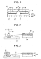
- FIG. 1 is a sectional view of a heat-insulating mold according to a first embodiment of the present invention.
- reference numeral 11 denotes a mold apparatus (a heat-insulating mold) for molding a product such as a light guide plate or a disc substrate
- reference numeral 12 denotes a stationary mold (a first mold)
- reference numeral 13 denotes a movable mold (a second mold) disposed such that it can advance toward the stationary mold 12 and retreat away therefrom
- C1 and C2 denote cavities formed between the stationary mold 12 and the movable mold 13 as a result of mold clamping.
- the movable mold 13 includes an upper plate (a mold plate; a first mold component) 21 and a lower plate (a support plate; a second mold component) 22, which supports the upper plate 21.
- An insert (a transfer member) 24 is attached to a surface of the upper plate 21 which surface faces the stationary mold 12.
- a transfer surface including fine projections and depressions formed in a predetermined pattern is formed on a surface of the insert 24 which surface faces the stationary mold 12.
- the upper plate 21 and the lower plate 22 are made of stainless steel so as to maintain rigidity
- the insert 24 is made mainly of nickel (Ni) so as to realize good machinability.
- a heat-insulating layer 25 made of an insulating material and having a densified surface is formed on a surface of the upper plate 21 which surface comes into contact with the insert 24.
- a temperature-control-medium flow channel 23 is formed in the lower plate 22.
- a temperature control medium, such as water or air, fed from an unillustrated temperature controller flows through the temperature-control-medium flow channel 23 so as to cool the mold apparatus 11 and an unillustrated resin (a molding material) within the cavities C1 and C2.
- reference numeral 15 denotes a sprue formed in the stationary mold 12, and a distal end of the sprue 15 is connected to the cavities C1 and C2 via gates g1 and g2, respectively, each of which serves as a resin inflow section.
- the insert 24 is attached to the upper plate 21 of the movable mold 13, and the heat-insulating layer 25 is formed on the surface of the upper plate 21 which surface comes into contact with the insert 24.
- the embodiment may be modified such that an upper plate and a lower plate are provided on the stationary mold 12 side, an insert is attached to a surface of the upper plate which surface faces the movable mold 13, a heat-insulating layer is formed on a surface of the upper plate which surface comes into contact with the movable mold 13, and a temperature-control-medium flow channel is formed in the lower plate.
- the movable plate 13 is composed of the upper plate 21 and the lower plate 22.
- the movable plate 13 may be formed as a single member.
- the movable mold 13 can be advanced for mold closing, and then brought into contact with the stationary mold 12 for mold clamping. As a result, the above-described cavities C1 and C2 are formed between the stationary mold 12 and the movable mold 13. Further, the movable mold 13 can be separated from the stationary mold 12 for mold opening.
- the mold-clamping apparatus includes a stationary platen (a first platen); a toggle support (a base plate); tie bars disposed and extending between the stationary platen and the toggle support; a movable platen (a second platen) disposed such that the movable platen faces the stationary platen and can advance and retreat along the tie bars; a toggle mechanism disposed between the movable platen and the toggle support; a mold-clamping motor serving as a drive section for mold clamping; etc.
- the above-described stationary mold 12 and movable mold 13 are attached to the stationary platen and the movable platen, respectively, such that the stationary mold 12 and the movable mold 13 face each other.
- an unillustrated injection apparatus is disposed such that it faces the stationary platen.
- the injection apparatus includes a heating cylinder (a cylinder member); a screw disposed in the heating cylinder so that the screw can rotate and can advance and retract; an injection nozzle attached to a front end of the heating cylinder; a hopper disposed in the vicinity of a rear end of the heating cylinder; a metering motor (a drive section for metering) connected to the screw; an injection motor (a drive section for injection) connected to the screw; etc.
- the toggle mechanism When the mold-clamping motor of the mold-clamping apparatus is driven, the toggle mechanism is extended, and the movable platen is advanced, whereby mold closing is performed, and the movable mold 13 is brought into contact with the stationary mold 12. Subsequently, when the mold-clamping motor is driven further, the toggle mechanism generates a mold-clamping-force, with which the movable mold 13 is pressed against the stationary mold 12, whereby mold clamping is performed.
- the metering motor is driven in a metering step so as to rotate the screw.
- resin supplied from the hopper is heated and melted within the heating cylinder, and is moved forward and accumulated forward of the screw. Accordingly, the screw is retreated to a predetermined position.
- the injection nozzle of the injection apparatus is pressed against the sprue 15 of the mold apparatus 11 in a clamped state; and the injection motor is driven so as to advance the screw.
- the resin accumulated forward of the screw is injected from the injection nozzle, and is charged into the cavities C1 and C2 via the gates g1 and g2, respectively.
- the resin within the cavities C1 and C2 is cooled and hardened by the temperature control medium, and, at that time, the pattern of the transfer surface of the insert 24 is transferred to the resin.
- the mold-clamping motor is driven in the reverse direction.
- the toggle mechanism contracts so as to retreat the movable platen, whereby mold opening is performed. In this manner, a molded product can be obtained.
- cooling temperature which is the temperature of the entire mold apparatus, including the wall surface of the cavity, is set to a temperature several tens of degrees (Celsius) lower than the glass transition temperature of the resin so as to cool the resin.
- a surface-hardened layer (skin layer) is formed instantaneously.
- the state of formation of the surface-hardened layer changes depending on molding conditions, the type of the resin, etc., if the surface-hardened layer grows, proper molding is hindered at portions of the resin which portions are in contact with the wall surfaces of the cavities C1 and C2, so that weld, transfer defect, or a like molding defect occurs.
- the heat-insulating layer 25 is formed on the back side of the insert 24 as described above. Therefore, the insert 24 can be thermally insulated from a mold main portion of the movable mold 13 in which the heat-insulating layer 25 is not formed.
- the temperature of the resin is temporarily maintained by the heat-insulating layer 25.
- formation and growth of a surface-hardened layer can be delayed, and transfer of the pattern of the transfer surface can be completed before the formation and growth of the surface-hardened layer. Therefore, occurrence of molding defects can be prevented.
- the cooling temperature of the mold apparatus 11 can be lowered, the resin having flowed into the cavities C1 and C2 via the gates g1 and g2 are quickly cooled as it moves within the cavities C1 and C2 toward the side away from the gates.
- the mold apparatus is more quickly brought into a state in which mold opening can be performed, as compared with the case of an ordinary mold apparatus.
- a mold-opening stand-by time between the timing at which charging of the resin is started and the timing at which the mold opening is started can be shortened, whereby molding cycle can be shortened.
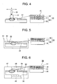
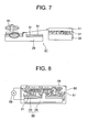
- FIG. 2 is a view showing a first step of a method of forming a heat-insulating layer in the first embodiment of the present invention.
- FIG. 3 is a view showing a second step of the method of forming the heat-insulating layer in the first embodiment of the present invention.
- FIG. 4 is a view showing a third step of the method of forming the heat-insulating layer in the first embodiment of the present invention.
- FIG. 5 is a view showing a fourth step of the method of forming the heat-insulating layer in the first embodiment of the present invention.
- FIG. 6 is a view showing a fifth step of the method of forming the heat-insulating layer in the first embodiment of the present invention.
- FIG. 7 is a view showing a sixth step of the method of forming the heat-insulating layer in the first embodiment of the present invention.
- reference numeral 28 denotes a base member which is made of steel and serves as a prototype of the upper plate 21; and 29 denotes a nozzle.
- the nozzle 29 is moved in a direction of arrow A so as to thermally spray a ceramic material (a heat-insulating material) having excellent heat-insulating properties.
- a ceramic material a heat-insulating material
- powder of the ceramic material is melted in a hot flame injected from the nozzle 29, and is deposited on the base member 28.
- a film (a porous surface layer portion) 31 which includes a large number of pores 32 and which has excellent heat-insulating properties is formed on the base member 28.
- zirconia is used as the ceramic material.
- the surface of the film 31 is polished by means of a polishing apparatus 35, whereby a first laminate 34 composed of the base member 28 and the film 31 is formed.
- a nozzle 36 for performing slurry coating is moved in the direction of arrow A.
- slurry 37 formed by thoroughly dispersing powder of a ceramic material (a heat-insulating material) into a solvent along with organic polymers such as a dispersant, a binder, etc., is injected from the nozzle 36 and applied onto the first laminate 34.
- a film (a porous surface layer portion; a slurry coat layer) 38 which includes a large number of pores 41 and which has excellent heat-insulating properties is formed on the film 31.
- a film (a porous surface layer portion; a slurry coat layer) 38 which includes a large number of pores 41 and which has excellent heat-insulating properties is formed on the film 31.
- zirconia is used as the ceramic material.
- a second laminate 39 is formed by the first laminate 34 and the film 38.
- the second laminate 39 is immersed into an impregnating agent 45 stored in a container 43, and impregnated therewith, whereby chemical densification is performed.
- the impregnating agent 45 is composed of fine particles of a ceramic material (a heat-insulating material) (in the present embodiment, silica alumina (SiO 2 ⁇ Al 2 O 3 )) and a binder for binding the particles (in the present embodiment, chrome oxide (Cr 2 O 3 )).
- a ceramic material in the present embodiment, silica alumina (SiO 2 ⁇ Al 2 O 3 )
- a binder for binding the particles in the present embodiment, chrome oxide (Cr 2 O 3 )
- the second laminate 39 is placed in a heat treatment furnace 47, is heated by means of heaters (heating bodies) 48 and 49, and fired. As a result, a very dense composite ceramic layer 51 is formed at the surface of the film 38.
- the fourth step and the fifth step are repeated alternately, whereby substantially the entire film 38 becomes the composite ceramic layer 51.
- the surface of the composite ceramic layer 51 is polished by means of the polishing apparatus 35, whereby the upper plate 21, which is composed of the base member 28, the film 31, and the composite ceramic layer 51, is completed.
- the surface roughness (arithmetical mean roughness) Ra of the composite ceramic layer 51 is set to fall within a range of 50 nm and 200 nm, inclusive, preferably, to be greater than 0 nm but not greater than 200 nm, whereby the composite ceramic layer 51 is made very smooth.
- the film 31 has a thickness of several hundreds of microns (e.g., about 300 ⁇ m), and the composite ceramic layer 51 has a thickness of several hundreds of microns (e.g., not less than 100 ⁇ m but less than 300 ⁇ m).
- the pores 41 at the surface of the film 38 are closed by means of impregnation, and the very dense composite ceramic layer 51 is formed by means of firing. Therefore, the surface of the film 38 can be made very smooth. Accordingly, it becomes possible to enhance the durability of the heat-insulating layer 25, and to prevent formation of scraping marks on the back surface of the insert 24 to thereby improve the durability of the insert 24.
- the film 31 is formed on the base member 28 and the composite ceramic layer 51 is formed on the film 31, even when expansion and contraction occur in a heat cycle repeated as a result of repeated molding operation, a surface of the base member 28 and a corresponding surface of the film 31 do not scrape against each other, and a surface of the film 31 and a corresponding surface of the composite ceramic layer 51 do not scrape against each other. Thus, wear of the film 31 and the composite ceramic layer 51 can be prevented, whereby the durability of the heat-insulating layer 25 can be improved.
- the film 31 formed by use of zirconia or the like is not required to be thick, the brittleness of the film 31 can be lowered. Accordingly, even when injection force, mold-clamping-force, or the like is large, the film 31 becomes unlikely to be broken. Further, even when the base member 28 and the film 31 differ in coefficient of thermal expansion, the film 31 does not break during a heat cycle. Therefore, the durability of the heat-insulating layer 25 can be improved.
- FIG. 8 is a first view showing a method of forming a heat-insulating layer in a second embodiment of the present invention.
- FIG. 9 is a second view showing the method of forming a heat-insulating layer in the second embodiment of the present invention.
- a ceramic material (zirconia) is thermally sprayed on the base member 28, which is made of steel and serves as a prototype of the upper plate 21, as in the first step in the first embodiment, or slurry containing a ceramic material (zirconia) is applied to the base member 28, as in the third step in the first embodiment, whereby a film (a porous surface layer portion) 53 which includes a large number of pores and which has excellent heat insulating properties is formed.
- a first laminate 54 is formed by the base member 28 and the film 53.
- the first laminate 54 is immersed into a plating bath 56 and the film 53 is plated, whereby electrochemical densification is performed.
- nickel (Ni) electroless plating is performed.
- a nickel plate 58 is disposed within the plating bath 56, and the base member 28 and the plate 58 are connected together via a power source 59.
- the surface of the film 53 is polished by means of an unillustrated polishing apparatus, whereby the upper plate 21 ( FIG. 1 ) , which is composed of the base member 28, the film 53, and a composite plating layer 63, is completed. At that time, the surface roughness of the composite plating layer 63 is on the order of several tens of nm, and the composite plating layer 63 becomes very smooth.
- another function can be imparted to the composite plating layer 63 by mixing fine particles 61 into the plating solution used for performing plating on the film 53.
- fine particles 61 registered trademark
- DLC dimethylcellulose
- the composite plating layer 63 is formed so as to reduce the coefficient of friction of the surface of the film 53 and prevent separation of the plating film.
- the fine particles 61 of Teflon are mixed, the heat-insulating properties of Teflon can be utilized, so that the heat-insulating properties of the heat-insulating layer 25 can be enhanced.
- the surfaces of the fine particles 61 may be electrified or a preliminary treatment may be performed for the fine particles 61 in order to allow the fine particles 61 to uniformly disperse within the plating solution, to thereby prevent precipitation or aggregation of the fine particles 61.
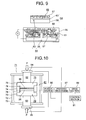
- FIG. 10 is a schematic view showing a discharge plasma sintering apparatus according to a third embodiment of the present invention.
- reference numeral 71 denotes a discharge plasma sintering apparatus
- reference numeral 72 denotes a sealed housing having a circular tubular shape.
- a chamber 73 within the housing 72 is connected to an unillustrated vacuum pump, which serves as a vacuum generation source, and is evacuated upon activation of the vacuum pump.
- an inert gas such as argon gas may be charged into the chamber 73.
- an unillustrated cooling pipe is provided within the wall of the housing 72, and unillustrated cooling water, which serves as a cooling medium, is circulated through the cooling pipe, whereby the chamber 73 is cooled.
- the cooling pipe is connected to an unillustrated cooling apparatus, and cooling water is supplied to the cooling pipe.
- Reference numeral 74 denotes a cylindrical die formed of an electrically conductive material such as graphite.
- An upper punch (a first punch) 75 and a lower punch (a second punch) 76 are disposed above and below the die 74.
- Each of the upper punch 75 and the lower punch 76 assumes a bar-like shape, and is formed of an electrically conductive material such as graphite.
- the upper punch 75 and the lower punch 76 are disposed such that they face each other.
- the upper punch 75 includes a punch main portion 78 projecting toward the interior of the die 74, and a flange-shaped pressing portion 79 provided at the upper end of the upper punch 75 and formed integrally with the punch main portion 78.
- the lower punch 76 includes a punch main portion 78 projecting toward the interior of the die 74, and a flange-shaped pressing portion 79 provided at the lower end of the lower punch 76 and formed integrally with the punch main portion 78.
- the die 74, the upper punch 75, and the lower punch 76 constitute a sintering die 81.
- the die 74, the upper punch 75, and the lower punch 76 are formed of graphite.
- an electrically conductive material whose melting point is equal to or higher than 1100°C, such as tungsten (W), molybdenum (Mo), or carbon (C), may be used.
- An upper electrode (a first electrode) 82 is disposed above the upper punch 75 and a lower electrode (a second electrode) 83 is disposed below the lower punch 76 such that they extend vertically.
- the upper electrode 82 has an electrode terminal 84
- the lower electrode 83 has an electrode terminal 85.
- the upper electrode 82 and the lower electrode 83 are connected to a DC power source 86 via the electrode terminals 84 and 85.
- the upper electrode 82 and the lower electrode 83 are disposed such that they can move vertically, and a pressing mechanism 87 is connected to the upper end of the upper electrode 82 and the lower end of the lower electrode 83.
- a pressing force P generated by the pressing mechanism 87 is transmitted to the upper electrode 82 and the lower electrode 83 so as to move the upper electrode 82 downward and move the lower electrode 83 upward.
- the base member 28, which serves as a prototype of the upper plate 21 ( FIG. 1 ), is set within the die 74, and sintering powder 88; e.g., powder of zirconia or yttria, is charged onto the base material 28 as a ceramic material (a heat-insulating material).
- the pressing mechanism 87 is operated so as to move the upper electrode 82 and the lower electrode 83 to thereby press the sintering powder 88 with the above-described pressing force P.
- a servomotor, a speed reducer, etc. are used as a drive section 89 of the pressing mechanism 87, a hydraulic cylinder, a pneumatic cylinder, or the like may be used.
- the upper electrode 82 and the lower electrode 83 are disposed such that they can move vertically, and the upper electrode 82 and the lower electrode 83 are moved so as to press the sintering powder 88.
- the present embodiment may be modified in such a manner that one of the upper electrode 82 and the lower electrode 83 is fixed, the other electrode is disposed to be movable, and the other electrode is moved so as to press the sintering powder 88.
- a control section 91 is provided so as to generate a predetermined pressing force P by the pressing mechanism 87 and transmit the pressing force P to the upper electrode 82 and the lower electrode 83 and to generate a predetermined pulse of a predetermined voltage by the power source 86.
- the control section 91 is connected to the power source 86, and is connected to the pressing mechanism 87 via the drive section 89.
- the upper electrode 82 is first moved upward so as to move the upper punch 75 upward, to thereby open the upper end of the die 74.
- the base member 28 and the sintering powder 88 are placed into a bottomed charging chamber formed by the die 74 and the lower punch 76.
- unillustrated pressing processing means (a pressing processing section) of the control section 91 performs pressing processing so as to operate the pressing mechanism 87 by driving the drive section 89, to thereby move the upper electrode 82 and the lower electrode 83.
- Unillustrated voltage application processing means (a voltage application processing section) of the control section 91 then performs voltage application processing so as to operate the power source 86, to thereby apply voltage (pluses) between the upper electrode 82 and the lower electrode 83 for about 10 minutes.
- a voltage within a range of 0.1 V to 5 V, inclusive is applied between the upper electrode 82 and the lower electrode 83 such that a pulsed DC current within a range of 1000 A to 8000 A, inclusive, flows therebetween.
- a pulsed DC current is supplied.
- an AC current or a current having a rectangular waveform, a triangular waveform, a trapezoidal waveform, or a like waveform may be supplied.
- a current having a constant magnitude may be supplied for a certain period of time.
- the sintering powder 88 is heated to a temperature within a range of 500°C to 3000°C, inclusive, so that the sintering powder 88 is sintered by means of discharge plasma sintering, and becomes a sintered body. In this case, heat is generated at points where particles of the sintering powder 88 are in contact with one another, and the particles are joined together.
- a predetermined binder is added to the sintering powder 88 in order to facilitate handling of the sintering powder 88, the binder disappears when the pulsed current flows through the sintering powder 88.
- the heat-insulating layer 25 is formed on the base member 28, and a laminate is formed by the base member 28 and the heat-insulating layer 25. Subsequently, with a slight delay, the die 74, the upper punch 75, and the lower punch 76 are heated by means of Joule heat, to thereby maintain the temperature of the sintered body. Subsequently, they are cooled by means of cooling water.
- the upper punch 75 and the upper electrode 82 are moved upward, and the laminate is removed from the charging chamber.
- the ceramic material is physically densified by means of discharge plasma sintering, and the density of the ceramic material can be increased to at least 99% the theoretical value.
- the surface of the heat-insulating layer 25 is polished by use of an unillustrated polishing apparatus, the surface can be made smooth to a level corresponding to the grain size of the sintering powder 88.
- thermal influence on the base member 28 can be reduced.
- a thin sheet may be formed by a sintered body and fixedly provided between the upper plate 21 and the insert 24 by means of bonding.
- one type of sintering powder 88 is charged on the base member 28 within the sintering die 81.
- a plurality of types of sintering powders may be charged so as to form a plurality of heat-insulating layers.
- the properties of a heat-insulating layer(s) on the side toward the base member 28 can be determined to match the properties of the base member 28, and the properties of a heat-insulating layer(s) on the side toward the insert 24 can be determined to match the properties of the insert 24. Therefore, durability of the heat-insulating mold can be improved.
- the content of the sintering powder is changed gradually so as to form a gradient layer, to thereby improve the joint between adjacent heat-insulating layers.
Landscapes
- Engineering & Computer Science (AREA)
- Mechanical Engineering (AREA)
- Manufacturing & Machinery (AREA)
- Moulds For Moulding Plastics Or The Like (AREA)
- Manufacturing Optical Record Carriers (AREA)
Applications Claiming Priority (2)
| Application Number | Priority Date | Filing Date | Title |
|---|---|---|---|
| JP2006330395A JP4750681B2 (ja) | 2006-12-07 | 2006-12-07 | 断熱金型、金型部品、成形機及び断熱金型の製造方法 |
| PCT/JP2007/073494 WO2008069235A1 (ja) | 2006-12-07 | 2007-12-05 | 断熱金型、金型部品、成形機及び断熱金型の製造方法 |
Publications (2)
| Publication Number | Publication Date |
|---|---|
| EP2100710A1 true EP2100710A1 (de) | 2009-09-16 |
| EP2100710A4 EP2100710A4 (de) | 2012-11-07 |
Family
ID=39492118
Family Applications (1)
| Application Number | Title | Priority Date | Filing Date |
|---|---|---|---|
| EP07859722A Withdrawn EP2100710A4 (de) | 2006-12-07 | 2007-12-05 | Wärmedämmform, formkomponenten, formmaschine und verfahren zur herstellung der wärmedämmform |
Country Status (7)
| Country | Link |
|---|---|
| US (1) | US20100055225A1 (de) |
| EP (1) | EP2100710A4 (de) |
| JP (1) | JP4750681B2 (de) |
| KR (1) | KR20090085668A (de) |
| CN (1) | CN101553349A (de) |
| TW (1) | TW200824878A (de) |
| WO (1) | WO2008069235A1 (de) |
Cited By (1)
| Publication number | Priority date | Publication date | Assignee | Title |
|---|---|---|---|---|
| EP2581191A4 (de) * | 2010-06-14 | 2014-01-01 | Polyplastics Co | Chipherstellungsverfahren |
Families Citing this family (3)
| Publication number | Priority date | Publication date | Assignee | Title |
|---|---|---|---|---|
| SG11201400407YA (en) * | 2011-09-05 | 2014-05-29 | Polyplastics Co | Mold |
| CN105517378B (zh) * | 2014-09-22 | 2019-09-20 | 富泰华工业(深圳)有限公司 | 壳体及其制备方法,应用其的电子装置 |
| CN109211970B (zh) * | 2018-11-09 | 2021-03-30 | 中国兵器工业第五九研究所 | 隔热性能测试装置、隔热性能测试方法及应用 |
Family Cites Families (24)
| Publication number | Priority date | Publication date | Assignee | Title |
|---|---|---|---|---|
| US2485724A (en) * | 1945-12-21 | 1949-10-25 | Pittsburgh Corning Corp | Method of making lightweight cellular materials |
| EP0211579B1 (de) * | 1985-08-02 | 1990-03-28 | Ngk Insulators, Ltd. | Verfahren zur Herstellung eines Bauelements aus gesintertem Siliciumnitrid |
| JPS6272583A (ja) * | 1985-09-26 | 1987-04-03 | 日本碍子株式会社 | 高温構造部材用炭化珪素焼結部材 |
| JPS63144211U (de) * | 1987-03-16 | 1988-09-22 | ||
| US4983247A (en) * | 1989-08-07 | 1991-01-08 | General Electric Company | Method for producing resin rich surface layer on composite thermoplastic material |
| US5431367A (en) * | 1992-08-28 | 1995-07-11 | General Electric Company | Multilayer injection molds having improved surface properties |
| JPH06246797A (ja) * | 1992-12-28 | 1994-09-06 | Nippon Steel Chem Co Ltd | 成形品外観へのヒケ防止方法および射出成形用金型 |
| US5458818A (en) * | 1993-08-31 | 1995-10-17 | General Electric Co. | Insulated mold structure for injection molding of optical disks |
| JP3183171B2 (ja) * | 1996-05-31 | 2001-07-03 | トヨタ自動車株式会社 | 断熱セラミック層およびその形成方法 |
| TW476958B (en) * | 1999-02-09 | 2002-02-21 | Ricoh Kk | Optical disk and method of producing the same |
| JP4594486B2 (ja) * | 2000-03-30 | 2010-12-08 | 長野県 | キャビティ形成金型の製造方法、およびキャビティ形成金型 |
| JP2003014938A (ja) * | 2001-04-12 | 2003-01-15 | Mitsubishi Engineering Plastics Corp | 透明樹脂製の導光板及びその成形方法、入れ子、金型組立体、並びに、面状光源装置 |
| US6787071B2 (en) * | 2001-06-11 | 2004-09-07 | General Electric Company | Method and apparatus for producing data storage media |
| JP4098982B2 (ja) * | 2001-07-02 | 2008-06-11 | Spsシンテックス株式会社 | 表面成形用成形型の製造方法 |
| JP2004050825A (ja) * | 2002-05-31 | 2004-02-19 | Sumitomo Heavy Ind Ltd | 金型 |
| JP4181017B2 (ja) * | 2002-11-13 | 2008-11-12 | 株式会社東伸精工 | 成形用金型 |
| WO2004058479A1 (en) * | 2002-12-31 | 2004-07-15 | Shinill Kang | Molding system for molding micro pattern structure having micro heating element and method for fabricating mold insert for molding micro pattern structure used therein |
| JP4197183B2 (ja) * | 2003-03-03 | 2008-12-17 | パナソニック株式会社 | ディスク基板成形用金型およびディスク基板の製造方法 |
| JP4016278B2 (ja) * | 2003-12-25 | 2007-12-05 | セイコーエプソン株式会社 | 成形型および成形品の製造方法 |
| WO2005113466A1 (ja) * | 2004-05-20 | 2005-12-01 | Kabushiki Kaisha Toshiba | 高熱伝導性窒化ケイ素焼結体及び窒化ケイ素構造部材 |
| US20050285287A1 (en) * | 2004-06-29 | 2005-12-29 | Konica Minolta Opto, Inc. | Injection mold and method for molding an optical element |
| JP4554330B2 (ja) * | 2004-10-21 | 2010-09-29 | 株式会社リコー | 高耐久性を有する断熱スタンパ構造 |
| KR20080038080A (ko) * | 2005-08-18 | 2008-05-02 | 코니카 미놀타 옵토 인코포레이티드 | 광학 소자 성형용 금형 및 그 제조 방법 |
| EP2008786A4 (de) * | 2006-04-20 | 2010-03-17 | Sumitomo Heavy Industries | Harzformvorrichtung und harzformverfahren |
-
2006
- 2006-12-07 JP JP2006330395A patent/JP4750681B2/ja not_active Expired - Fee Related
-
2007
- 2007-12-05 WO PCT/JP2007/073494 patent/WO2008069235A1/ja not_active Ceased
- 2007-12-05 EP EP07859722A patent/EP2100710A4/de not_active Withdrawn
- 2007-12-05 TW TW096146273A patent/TW200824878A/zh not_active IP Right Cessation
- 2007-12-05 US US12/312,850 patent/US20100055225A1/en not_active Abandoned
- 2007-12-05 KR KR1020097011373A patent/KR20090085668A/ko not_active Ceased
- 2007-12-05 CN CNA200780045149XA patent/CN101553349A/zh active Pending
Cited By (1)
| Publication number | Priority date | Publication date | Assignee | Title |
|---|---|---|---|---|
| EP2581191A4 (de) * | 2010-06-14 | 2014-01-01 | Polyplastics Co | Chipherstellungsverfahren |
Also Published As
| Publication number | Publication date |
|---|---|
| TWI344414B (de) | 2011-07-01 |
| WO2008069235A1 (ja) | 2008-06-12 |
| TW200824878A (en) | 2008-06-16 |
| JP2008142952A (ja) | 2008-06-26 |
| CN101553349A (zh) | 2009-10-07 |
| JP4750681B2 (ja) | 2011-08-17 |
| US20100055225A1 (en) | 2010-03-04 |
| KR20090085668A (ko) | 2009-08-07 |
| EP2100710A4 (de) | 2012-11-07 |
Similar Documents
| Publication | Publication Date | Title |
|---|---|---|
| JP3227454B2 (ja) | 放電表面処理用電極及びその製造方法並びに放電表面処理方法及び装置 | |
| US8216439B2 (en) | Hybrid slip casting-electrophoretic deposition (EPD) process | |
| CA2298367A1 (en) | Method of electric sintering method and mold for use in the method | |
| CN108558398A (zh) | 一种脉冲放电室温闪速烧结纳米陶瓷材料的方法 | |
| EP2100710A1 (de) | Wärmedämmform, formkomponenten, formmaschine und verfahren zur herstellung der wärmedämmform | |
| US6929829B2 (en) | Method and device discharging surface treatment | |
| GB2257388A (en) | Electrically heated moulding die | |
| CN1835835A (zh) | 可加热的工具 | |
| EP1366878A1 (de) | Werkzeug und Verfahren zu seiner Herstellung | |
| CN1910676B (zh) | 绝热压模结构 | |
| JP5547864B2 (ja) | 放電表面処理方法及び装置 | |
| JPWO2000050194A1 (ja) | 放電表面処理方法及び装置 | |
| CN111070375B (zh) | 一种冻结陶瓷浆料3d打印机构 | |
| DE102010018590A1 (de) | Verfahren zum Spritzgießen eines Formteils und Spritzgießwerkzeug | |
| JP2004050825A (ja) | 金型 | |
| WO2007007779A1 (ja) | 成型装置とその製造方法、及び成型方法 | |
| CN100584575C (zh) | 注射压缩成形方法 | |
| JPH05116182A (ja) | プラスチツク成形型 | |
| CN102892917A (zh) | 包括使用激光金属沉积设备将电阻性粉末转化成熔合加热元件的工艺 | |
| CN100446957C (zh) | 注射成型装置以及其上使用的构件以及表面处理方法 | |
| Bürgisser et al. | Ceramic injection moulding: The impact of variotherm and conformal cooling technology on part quality and process capability | |
| KR100354864B1 (ko) | 미세방전가공용 방전전극의 제조방법 | |
| JP2006150749A (ja) | レンズ成形方法及び成形金型 | |
| JP2006213004A (ja) | 射出成形機用部材並びに被膜形成方法 | |
| JP2025538779A (ja) | プレート状の燃料電池構成要素、特にバイポーラプレートを製造するための方法およびこの方法により製造された燃料電池構成要素 |
Legal Events
| Date | Code | Title | Description |
|---|---|---|---|
| PUAI | Public reference made under article 153(3) epc to a published international application that has entered the european phase |
Free format text: ORIGINAL CODE: 0009012 |
|
| 17P | Request for examination filed |
Effective date: 20090605 |
|
| AK | Designated contracting states |
Kind code of ref document: A1 Designated state(s): AT BE BG CH CY CZ DE DK EE ES FI FR GB GR HU IE IS IT LI LT LU LV MC MT NL PL PT RO SE SI SK TR |
|
| DAX | Request for extension of the european patent (deleted) | ||
| A4 | Supplementary search report drawn up and despatched |
Effective date: 20121010 |
|
| RIC1 | Information provided on ipc code assigned before grant |
Ipc: B29C 45/37 20060101ALI20121004BHEP Ipc: B29C 33/42 20060101AFI20121004BHEP Ipc: B29C 33/38 20060101ALI20121004BHEP |
|
| 17Q | First examination report despatched |
Effective date: 20131028 |
|
| STAA | Information on the status of an ep patent application or granted ep patent |
Free format text: STATUS: THE APPLICATION IS DEEMED TO BE WITHDRAWN |
|
| 18D | Application deemed to be withdrawn |
Effective date: 20140308 |