EP2100751B1 - Radfelge aus Verbundmaterial für ein schlauchloses Fahrradrad und ein mit einer solchen Radfelge ausgestattetes schlauchloses Fahrradrad - Google Patents
Radfelge aus Verbundmaterial für ein schlauchloses Fahrradrad und ein mit einer solchen Radfelge ausgestattetes schlauchloses Fahrradrad Download PDFInfo
- Publication number
- EP2100751B1 EP2100751B1 EP20080425161 EP08425161A EP2100751B1 EP 2100751 B1 EP2100751 B1 EP 2100751B1 EP 20080425161 EP20080425161 EP 20080425161 EP 08425161 A EP08425161 A EP 08425161A EP 2100751 B1 EP2100751 B1 EP 2100751B1
- Authority
- EP
- European Patent Office
- Prior art keywords
- rim
- radially outer
- layer
- outer portion
- hole
- Prior art date
- Legal status (The legal status is an assumption and is not a legal conclusion. Google has not performed a legal analysis and makes no representation as to the accuracy of the status listed.)
- Not-in-force
Links
Images


Classifications
-
- B—PERFORMING OPERATIONS; TRANSPORTING
- B60—VEHICLES IN GENERAL
- B60B—VEHICLE WHEELS; CASTORS; AXLES FOR WHEELS OR CASTORS; INCREASING WHEEL ADHESION
- B60B5/00—Wheels, spokes, disc bodies, rims, hubs, wholly or predominantly made of non-metallic material
- B60B5/02—Wheels, spokes, disc bodies, rims, hubs, wholly or predominantly made of non-metallic material made of synthetic material
-
- B—PERFORMING OPERATIONS; TRANSPORTING
- B60—VEHICLES IN GENERAL
- B60B—VEHICLE WHEELS; CASTORS; AXLES FOR WHEELS OR CASTORS; INCREASING WHEEL ADHESION
- B60B1/00—Spoked wheels; Spokes thereof
- B60B1/003—Spoked wheels; Spokes thereof specially adapted for bicycles
-
- B—PERFORMING OPERATIONS; TRANSPORTING
- B60—VEHICLES IN GENERAL
- B60B—VEHICLE WHEELS; CASTORS; AXLES FOR WHEELS OR CASTORS; INCREASING WHEEL ADHESION
- B60B21/00—Rims
- B60B21/02—Rims characterised by transverse section
- B60B21/04—Rims characterised by transverse section with substantially radial flanges
-
- B—PERFORMING OPERATIONS; TRANSPORTING
- B60—VEHICLES IN GENERAL
- B60B—VEHICLE WHEELS; CASTORS; AXLES FOR WHEELS OR CASTORS; INCREASING WHEEL ADHESION
- B60B21/00—Rims
- B60B21/12—Appurtenances, e.g. lining bands
-
- B—PERFORMING OPERATIONS; TRANSPORTING
- B60—VEHICLES IN GENERAL
- B60B—VEHICLE WHEELS; CASTORS; AXLES FOR WHEELS OR CASTORS; INCREASING WHEEL ADHESION
- B60B21/00—Rims
- B60B21/02—Rims characterised by transverse section
- B60B21/025—Rims characterised by transverse section the transverse section being hollow
-
- B—PERFORMING OPERATIONS; TRANSPORTING
- B60—VEHICLES IN GENERAL
- B60B—VEHICLE WHEELS; CASTORS; AXLES FOR WHEELS OR CASTORS; INCREASING WHEEL ADHESION
- B60B21/00—Rims
- B60B21/02—Rims characterised by transverse section
- B60B21/026—Rims characterised by transverse section the shape of rim well
-
- B—PERFORMING OPERATIONS; TRANSPORTING
- B60—VEHICLES IN GENERAL
- B60B—VEHICLE WHEELS; CASTORS; AXLES FOR WHEELS OR CASTORS; INCREASING WHEEL ADHESION
- B60B21/00—Rims
- B60B21/06—Rims characterised by means for attaching spokes, i.e. spoke seats
- B60B21/062—Rims characterised by means for attaching spokes, i.e. spoke seats for bicycles
-
- B—PERFORMING OPERATIONS; TRANSPORTING
- B60—VEHICLES IN GENERAL
- B60B—VEHICLE WHEELS; CASTORS; AXLES FOR WHEELS OR CASTORS; INCREASING WHEEL ADHESION
- B60B2900/00—Purpose of invention
- B60B2900/50—Improvement of
- B60B2900/511—Sealing
- B60B2900/5116—Sealing against air-loss
-
- Y—GENERAL TAGGING OF NEW TECHNOLOGICAL DEVELOPMENTS; GENERAL TAGGING OF CROSS-SECTIONAL TECHNOLOGIES SPANNING OVER SEVERAL SECTIONS OF THE IPC; TECHNICAL SUBJECTS COVERED BY FORMER USPC CROSS-REFERENCE ART COLLECTIONS [XRACs] AND DIGESTS
- Y10—TECHNICAL SUBJECTS COVERED BY FORMER USPC
- Y10T—TECHNICAL SUBJECTS COVERED BY FORMER US CLASSIFICATION
- Y10T29/00—Metal working
- Y10T29/49—Method of mechanical manufacture
- Y10T29/49481—Wheel making
- Y10T29/49492—Land wheel
- Y10T29/49524—Rim making
Definitions
- the present invention concerns a rim made from composite material for a tubeless bicycle wheel.
- the present invention also concerns a rim assembly and a tubeless wheel comprising such a rim, as well as a bicycle comprising such a wheel.
- a bicycle comprising such a wheel.
- the aforementioned bicycle is a racing bicycle.
- the present invention also concerns a method for manufacturing the aforementioned rim for a tubeless bicycle wheel.
- a bicycle wheel comprises a rim, on which a tyre is mounted, a hub and a plurality of spokes extending between the rim and the hub.
- the present patent application is referred to a so-called “tubeless" tyre, i.e. without an inner tube with annular extension, mounted between a radially outer portion of the rim and the tyre, which is inflated by introducing air through an inflation valve of such a tube.
- the inflated inner tube presses against the tyre, taking it into the operative condition of desired "inflation".
- the tyre is mounted airtight on a radially outer portion of the rim, so as to form an airtight annular chamber in which there is pressurised air introduced through an inflation valve associated with the rim at a suitable through hole formed in the radially outer portion of the rim. Air is put into such a chamber until the tyre has reached the operative condition of desired "inflation".
- Such rims are produced with a curing step in a suitable mould, maintaining a predetermined high temperature for a predetermined time. A through hole for the inflation valve is then made on the rim obtained from the mould.
- the inflation valve normally comprises a threaded shank and a head made from elastically deformable material at an end thereof, such a head being widened with respect to the size of the shank.
- the shank is inserted into the through hole of the rim so that a radially inner surface of the widened head goes into abutment on the radially outer portion of the rim, on the side thereof directed towards the tyre.
- the shank is also longer than the thickness of the rim, so that a nut, or a ring nut, can be screwed onto the shank, from its end opposed to that of the widened head, until it comes into abutment on a radially inner surface of the rim.
- the widened head made from elastically deformable material is compressed against a surface of the radially outer portion of the rim arranged around the inflation hole, so as to make an airtight closure of the inflation hole itself.
- a rim made from composite material for a tubeless bicycle wheel manufactured according to the aforementioned prior art has some drawbacks, the main one of which is linked to the fact that the tubeless wheels comprising the aforementioned rim are frequently subject to deflation problems, which often become apparent after only a few kilometres run by the cyclist.
- US 4527839 and JP 58 191601 disclose wheels for vehicles, particularly wheels for small-sized vehicles such as motorcycles and motored tricycles.
- Such wheels comprise respective rims made from fiber-reinforced resin.
- the preamble of claim 1 is based on the rims of US 4527839 .
- FR 2474403 discloses a rim for a bicycle wheel manufactured by moulding of plastic material.
- the technical problem at the basis of the present invention is to provide a rim made from composite material for a tubeless bicycle wheel that gives the tubeless wheel a high reliability, so as to overcome the drawbacks aforementioned with reference to the prior art, in a simple and effective manner.
- the present invention in a first aspect thereof, concerns a rim made from composite material as recited in claim 1 .
- composite material it is meant a material comprising at least two components, including a polymeric matrix and a filler comprising for example structural fibres.
- impermeable-to-air material any material without porosity, crackings or defects such as to allow air to pass, like for example a rubber.
- a tubeless wheel comprising the aforementioned rim ensures that a correct inflation of the tyre is maintained for an extremely long time. Indeed, the Applicant has surprisingly found that a crucial point for the deflation is not so much the hole but the portion of composite material around the hole. By making this portion impermeable-to-air the wheel remains inflated for much longer periods. The Applicant has discovered that this advantageous effect is due to the fact that the impermeable layer prevents air from coming out through possible through cracks or porosities (even very small sized ones) that can form, in a totally uncontrollable way, in the polymeric matrix of the composite material when the through hole itself is made, for example with a drill.
- the integral association of the aforementioned layer with the radially outer portion has the advantage of avoiding that, in the mounted tubeless wheel, the layer becomes crumpled up under the head of the inflation valve, for example due to a rotation thereof whilst it is locked on the rim. Moreover, by integrally associating the layer with the radially outer portion, the assembly operations of the tubeless wheel are made easier.
- the aforementioned first layer is at least partially arranged to coat the radially outer portion.
- the aforementioned layer is arranged on a radially outer surface of the radially outer portion that is intended, in a configuration with the wheel mounted, to face the tyre.
- the aforementioned layer is in contact with the head of the inflation valve, when it is mounted on the rim.
- the aforementioned rim comprises a second layer made from impermeable-to-air material and arranged, around the through hole, on a radially inner surface of the radially outer portion, opposite the radially outer surface. In this way, an even greater reliability is advantageously ensured.
- the aforementioned layer is arranged at least partially on the side walls that define the through hole.
- the through hole can be initially closed by elastic impermeable-to-air material, which is, subsequently, centrally perforated to make a smaller sized hole, intended for the inflation valve, with the advantage that crackings do not form on such an impermeable-to-air material.
- the aforementioned layer is at least partially arranged inside the thickness of the radially outer portion.
- the aforementioned impermeable-to-air material is elastically deformable.
- the aforementioned layer is advantageously able to perfectly couple with the elastically deformable material of the head of a valve inserted in the inflation hole, so as to make an airtight coupling, even in the case in which the two respective contact surfaces are not homogeneous.
- both the aforementioned layer and the head of the valve are elastically deformable, it is possible to make a mutual adaptation to the shape disuniformities in their contact area, for which reason an optimal airtight seal is obtained.
- the aforementioned elastically deformable material is an elastomer.
- the aforementioned layer is glued to the radially outer portion.
- the aforementioned layer is co-moulded with the radially outer portion.
- the aforementioned layer is advantageously intimately linked with the composite material of the rim, substantially penetrating into the possible cracks of the composite material itself.
- the aforementioned layer is a resin.
- such a resin incorporates particles of elastomer, which give the resin the elastic properties.
- the resin is applied by spraying onto the radially outer portion.
- the aforementioned layer of resin is advantageously intimately linked with the composite material of the rim, substantially penetrating into the possible cracks of the composite material itself.
- such a method of application of the aforementioned layer reduces the time to make the rim of the invention.
- the aforementioned layer is arranged on a radially outer surface of the radially outer portion that is intended, in a configuration with the wheel mounted, to face the tyre.
- the airtight seal of the coupling between layer and head of the inflation valve mounted on the rim is advantageously improved, especially in the case in which the resin incorporates particles of elastomer.
- the aforementioned elastomer with which the aforementioned layer is made or that is incorporated into the aforementioned resin is selected from the group consisting of nitrite elastomers, hydrogenated nitrite elastomers, ethylene propylene (EPM o EPDM), chloroprene elastomers, polyethylene chlorosulfate, polyacrylic elastomers, and fluorine elastomers.
- EPM o EPDM ethylene propylene
- chloroprene elastomers polyethylene chlorosulfate
- polyacrylic elastomers polyacrylic elastomers
- fluorine elastomers fluorine elastomers
- the aforementioned layer of the rim of the invention has a heat resistance above 85°C, and more preferably above 130°C. Even more preferably, such a layer has a heat resistance above 180°C.
- heat resistance of a material it is meant its temperature of glass transition which is known as “Tg”, above which the cured material softens and possibly chemically degrades losing the physical and mechanical properties.
- the aforementioned layer can withstand the high temperatures reached by the rim in the case in which it stays closed in a car under the sun or in the case in which, in use, the braking takes place by friction of the brakes on an outer edge of the rim.
- the aforementioned layer of the rim of the invention has a "Shore A" surface hardness, according to the standard DIN 53505, within the range 63 ⁇ 20%, including extremes.
- the inflation valve can be mounted on the rim by tightening the nut, or the ring nut, with a very high force, without fear of damaging or lacerating the layer of impermeable-to-air material.
- a housing seat is formed for a widened head of the inflation valve.
- the assembly of the tubeless wheel comprising the aforementioned rim is made easy and an optimal coupling is made between rim and inflation valve.
- the housing seat allows the inflation valve to be kept in a desired position during the insertion into the respective through hole of the rim, ensuring the correct assembly of the inflation valve on the rim, irrespective of the ability of the operator who performs the assembly.
- the layer in the case in which the aforementioned layer is arranged on a radially outer surface of the radially outer portion of the rim, the layer has a transversal extension, measured transversally with respect to the through hole, which is greater than the transversal extension of the area of said radially outer surface of said radially outer portion, arranged around the through hole and that is intended, in a configuration with the wheel mounted, to be in contact with a widened head of the inflation valve.
- the aforementioned layer is integrally associated along the entire circumferential extension of the radially outer portion.
- the tubeless wheel comprising the aforementioned rim made from composite material has an even greater reliability than that obtained in the previous cases, since air is prevented from coming out from possible further cracks of the radially outer portion of the rim, which are created in areas located far from the through hole.
- Such further cracks can be created due to the processings to which the rim made from composite material is subjected, in particular in the milling processing carried out on the rim extracted from the setting mould, such a processing being necessary to make, on the rim, extremely precise surfaces of coupling with the tyre to prevent air leaks, the setting mould being unable to ensure such a high precision.
- the present invention concerns a rim assembly comprising a rim of the type described above and an inflation valve crossing the through hole.
- a rim assembly separately or in combination has all of the structural and functional characteristics discussed above with reference to the aforementioned rim and therefore it has all of the aforementioned advantages.
- the inflation valve of the aforementioned rim assembly comprises a widened head in abutment on the radially outer portion of the rim.
- the impermeable-to-air material of the aforementioned layer is a resin arranged on a radially outer surface of the radially outer portion of the rim
- the inflation valve of the aforementioned rim assembly is glued to the radially outer portion of the rim through the resin itself.
- the resin also acts as an adhesive.
- the inflation valve of the rim assembly of the invention comprises a widened head made from elastomer, formed in one piece with the elastomer of the aforementioned layer. In this way, the perfect airtight seal is substantially ensured.
- the present invention concerns a tubeless bicycle wheel comprising a rim assembly of the type described above and a tyre mounted in an airtight manner on the radially outer portion of the rim.
- such a tubeless wheel separately or in combination has all of the structural and functional characteristics discussed above with reference to the aforementioned rim, or the aforementioned rim assembly, respectively, and therefore it has all of the aforementioned advantages.
- the present invention concerns a bicycle comprising a tubeless wheel of the type described above.
- such a bicycle separately or in combination has all of the structural and functional characteristics discussed above with reference to the aforementioned tubeless wheel and therefore it has all of the aforementioned advantages.
- the present invention concerns a method for manufacturing a rim made from composite material as recited in claim 26.
- a tubeless wheel comprising the rim made with such a method ensures excellent reliability, thanks to the provision of the aforementioned impermeable-to-air layer, for the same reasons outlined above in reference to the rim of the invention.
- the aforementioned layer can be a resin.
- the present invention also concerns a further method for manufacturing a rim made from composite material for a tubeless bicycle wheel, with which a rim that is extremely reliable is obtained, too. Such a further method is recited in claim 27 .
- the aforementioned first layer of the methods of the invention is elastically deformable.
- the respective integral-making step comprises a gluing of the aforementioned at least one layer to the radially outer portion.
- the respective integral-making step preferably comprises a co-moulding of the aforementioned at least one layer with the radially outer portion.
- the aforementioned layer is advantageously intimately linked with the composite material of the rim, substantially penetrating into the possible cracks of the composite material itself.
- the respective integral-making step preferably comprises a spray application of the aforementioned at least one layer onto the radially outer portion.
- the aforementioned layer is advantageously intimately linked with the composite material of the rim, substantially penetrating into the possible cracks of the composite material itself.
- the aforementioned integral-making step comprises a setting of the said substantially annular body and of the aforementioned at least one layer, maintaining a temperature of between 85°C and 250°C for a predetermined time.
- the aforementioned layer is advantageously intimately linked with the composite material of the rim, substantially penetrating into the possible cracks of the composite material itself.
- the aforementioned at least one layer is integral-made along the entire circumferential extension of the radially outer portion.
- a tubeless wheel comprising the rim made in this way ensures an even greater reliability than that obtained in the previous cases, since air is prevented from coming out from possible further cracks of the radially outer portion of the rim, which are created - as mentioned above - in areas located far from the through hole.
- a tubeless bicycle wheel in accordance with the present invention is shown. Such a wheel is globally indicated with 1.
- the tubeless wheel 1 comprises a rim 5 coupled with a tyre 10 so as to make an airtight coupling. Between the rim 5 and the tyre 10 a chamber is formed in which air is introduced through an inflation valve 15 associated with the rim.
- the rim 5 is made from composite material, comprising a filler incorporated in a polymeric matrix.
- the composite material of the rim 5 comprises structural fibres incorporated in a polymeric material.
- the structural fibres are selected from the group consisting of carbon fibres, glass fibres, aramid fibres, ceramic fibres, boron fibres and combinations thereof.
- the carbon fibres are particularly preferred.
- the arrangement of said structural fibres in the polymeric material can be a random arrangement of small pieces or leaflet of structural fibres, an ordered substantially unidirectional arrangement of fibres, an ordered substantially bidirectional arrangement of fibres, or a combination of the above.
- the polymeric material is thermo-setting and preferably comprises an epoxy resin.
- this does not exclude the possibility of using a thermoplastic.
- the rim 5 is connected to a hub 20 through spokes 21. Finally the wheel 1, and therefore the rim 5, has a rotation axis A whose direction defines the axial direction of the wheel (or of the rim), whereas radial direction of the wheel (or of the rim) is referred, in the present description and in the subsequent claims, to a direction perpendicular to the axis A and passing through the axis A itself.
- Figure 2 illustrates the rim 5 in greater detail, in particular it is visible a radially outer portion 38 of the rim 5, i.e. directed towards the tyre 10. It should be observed that on such a portion 38 there are no through openings, apart from a through hole 30 for the inflation valve 15. In this way, to ensure the airtight seal between the radially outer portion 38 of the rim 5 and the tyre 10, it is sufficient that the coupling between hole 30 and inflation valve 15 is airtight.
- the radially outer portion can also comprise holes for the anchorage of the spokes, which are closed through the application of plugs or a tape.
- the rim 5 comprises a body 6 with substantially annular extension.
- the body 6 is shaped to house and hold, in a final inflation configuration of the tyre 10, borders 11 of radially inner end of the tyre 10 ( figure 3 ), in the jargon known as beads.
- the body 6 comprises the radially outer portion 38 with which the tyre 10 is intended to be coupled and a radially inner portion 36 made in a single piece with the radially outer portion 38.
- the radially inner portion 36 and the radially outer portion 38 form a tubular structure of the rim 5, the radially inner portion 36 and the radially outer portion 38 being connected by two opposite annular side flanks 35.
- the provision of the radially inner portion 36 in the wheel 1 of the present invention is particularly advantageous since it offers easy anchorage areas for the spokes 21 of the wheel 1.
- the radially outer portion 38 includes an annular bottom wall 38a, or upper bridge, where the hole 30 is made, and a pair of annular side walls 40, or fins, extending substantially in radial direction outwards starting from the bottom wall 38a.
- the side walls 40 comprise in particular a radially outer end portion 40a curved towards the median plane of the rim 5, so as to be able to hold the radially inner end borders 11 of the tyre 10.
- figure 3 shows how the side walls 40 cooperate with the tyre 10 and with the bottom wall 38a to form among them a seal chamber 42 of the air.
- the bottom wall 38a comprises an annular central recess 44, which extends radially towards the inside of the rim 5 for the entire circumferential extension, the hole 30 being made in such a recess 44.
- the inflation valve 15 comprises a threaded shank 15a and a head 46 at an end thereof, such a head 46 being widened with respect to the size of the shank 15a.
- the shank 15a is inserted into the hole 30 and the head 46 is inserted into the recess 44.
- a bottom surface 48 of the head 46 stops in abutment on a bottom surface of the recess 44.
- the head 46 is made from elastically deformable material, for example an elastomer, or it is coated with such a material, so as to be able to adapt to the bottom surface of the recess 44 that is around the hole 30, thus making the desired airtight seal.
- a layer of impermeable-to-air material 55 preferably elastically deformable, different from the composite material used to make the other parts of the rim 5, is integrally associated.
- the elastically deformable material is preferably an elastomer selected from the group consisting of nitrite elastomers, hydrogenated nitrite elastomers, ethylene propylene (EPM or EPDM), chloroprene elastomers, polyethylene chlorosulfate, polyacrylic elastomers and fluorine elastomers.
- EPM or EPDM ethylene propylene
- chloroprene elastomers polyethylene chlorosulfate
- polyacrylic elastomers polyacrylic elastomers
- fluorine elastomers fluorine elastomers.
- non silicon-based rubbers are preferred, since silicon-based rubbers have low adherence, which - in tests carried out by the Applicant - proved insufficient to ensure the desired airtight seal.
- the selection of the elastomer is also made based upon its heat resistance, for which reason the elastomers with heat resistance of above 85°, more preferably above 130° and even more preferably above 180° are preferred, so as to withstand the polymerisation cycles to which the rim 5 made from composite material is subjected.
- the preferred elastically deformable material amongst those indicated above possesses a tensile strength - according to standards DIN 53504 - within the range 4.6 ⁇ 20% MPa including extremes, a percentage extensibility - according to standards DIN 53504 - within the range 368 ⁇ 20% including extremes, and a surface hardness "Shore A" - according to standards DIN 53505 - within the range 63 ⁇ 20% including extremes.
- the impermeable material 55 is a resin, for example applied by spraying.
- the resin can be the same one used as matrix of the composite material, or a different resin.
- Such a resin is used by itself or incorporates particles of elastomer, which is preferably selected from those indicated above.
- the impermeable material 55 is preferably arranged to form a layer above the bottom wall 38a, as shown in figure 3 .
- the layer of impermeable material 55 extends in axial direction up to the side walls 40, so that its dimensions are large enough and makes its installation easier.
- the axial extension can be smaller, until it involves just the area in contact with the head 46 of the valve, as illustrated in the further embodiment of the invention shown in figure 4 .
- Figure 5 illustrates the preferred extension of the layer of impermeable material 55 in circumferential direction, said direction being defined with respect to the axis A of the rim 5.
- the extension is greater than the bottom surface 48 of the head 46 of the valve 15.
- Figure 6 illustrates a further embodiment of the invention, in which the circumferential extension of the layer of impermeable material 55 is equal to the extension of the bottom surface 48 of the head 46 of the valve 15. However, it is not excluded the possibility of using a circumferential extension of the layer of impermeable material 55 that is lower than the extension of the bottom surface of the head of the valve.
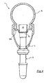
- Figure 7 illustrates a further embodiment of the invention in which the bottom wall 38a comprises two layers of impermeable material 55, a first layer being arranged on the side of the bottom wall 38a directed radially outwards, a second layer being arranged on the side of the bottom wall 38a directed radially inwards.
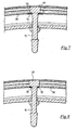
- Figure 8 illustrates a further embodiment of the invention in which all the thickness of the bottom wall 38a, in the area that surrounds the hole 30, consists of impermeable material 55, i.e. the through hole 30 is in this case defined by cylindrical side walls entirely made from impermeable material 55.
- FIG 11 illustrates a further embodiment that makes it clear how the essential function of the impermeable layer 55 is to obstruct the cracks when they appear on surface.
- an impermeable layer 55 is used consisting of the same, and only, resin as the rim, applied on the entire radially outer surface of the rim. This is advantageous because normally the radially outer portion of the rim 38 is subjected to a finishing processing to ensure the perfect airtight coupling between rim and tyre. Such a processing, however, can generate crevices at any point of the rim, or put in evidence porosities of the material by removing the most outer layer.
- the coating layer being able to be applied with extreme precision after the processings of the rim have been carried out, for example by spraying, covers the crevices or porosities that appear on surface without altering the regularity of the coupling profile.
- the coating layer is obviously cured subsequently with respect to the manufacture of the rim.
- Figure 12 illustrates a further variant in which the impermeable layer 55 is made from elastic material and is inserted inside the thickness of the radially most outer portion of the rim. In this way, given that during the processing for making the hole 30 the elastic material does not crack, it interrupts and seals possible crevices that may form in the polymeric matrix.
- the layer - or the layers - of impermeable material 55 are in any case integral to the bottom wall 38a of the rim 5, for example through gluing, co-moulding with the remaining composite material of the rim 5, or spray application.
- Figure 9 shows a further embodiment of a rim according to the present invention, which is globally indicated with 105.
- the rim 105 differs from the rim 5 of figure 3 because its bottom wall 138a comprises a housing seat 60 for the head of the valve (not shown).
- the seat 60 is a recess in the bottom wall 138a, which extends radially towards the inside of the rim 105.
- such a recess substantially at the centre of which the hole 30 is formed, is intended to house the widened head, for example quadrangular-shaped, of the inflation valve so that a side surface of such a head is in abutment with a corresponding side surface of the recess, so as to make it easy to correctly locate the valve in the hole 30.
- Figure 10 which is a section of the rim 105 according to the radial plane having trace X - X of figure 9 , passing close to but not at the seat 60, shows in the foreground the transversal profile of the bottom wall 138a and in the background, with a broken line, the transversal profile of the aforementioned recess for the head of the valve (not shown).
- the layer of impermeable material 55 coats at least one bottom surface of the seat 60.
- the rim of composite material of the invention englobing the layer of impermeable material 55 is made by prearranging a plurality of overlapping layers of composite material, to form the bearing structure of the rim, and then arranging a further layer of impermeable material 55, elastic and/or resinous, at least in the area where the hole for the inflation valve shall be made.
- the whole of the aforementioned layers of the two materials is cured by subjecting it to a temperature of between 85°C and 250°C for a predetermined time.
- the curing temperature is greater than or equal to 120°C, and more preferably is greater than or equal to 130°C. Even more preferably, the curing temperature is greater than or equal to 170°C, whereas the best results are obtained with a curing temperature greater than or equal to 180°C.
- the layer of impermeable material 55 can be glued around the hole for the inflation valve, even if in this case the impermeable material 55 is linked less intimately with the composite material of the rim. In any case, the sealing effect of the cracks is ensured, since the points in which they appear on surface are covered.
- the coating layer 55 is applied to the rim after the curing and subsequently to the mechanical finishing processings, so as to subsequently seal the possible crevices that may have formed.
Landscapes
- Engineering & Computer Science (AREA)
- Mechanical Engineering (AREA)
- Chemical & Material Sciences (AREA)
- Materials Engineering (AREA)
- Tires In General (AREA)
- Check Valves (AREA)
Claims (33)
- Felge (5, 105), die aus Verbundmaterial besteht, für ein schlauchloses Rad (1) für Fahrräder, wobei sie einen radial außenliegenden Abschnitt (38) umfasst, der zur Verbindung mit einem Reifen (10) geformt ist, und der radial außenliegende Abschnitt (38) ein Durchgangsloch (30) für ein Aufblasventil (15) umfasst, wobei um das Loch (30) herum wenigstens eine erste luftundurchlässige Schicht (55) integral mit dem radial außenliegenden Abschnitt (38) verbunden ist, dadurch gekennzeichnet, dass die wenigstens eine erste luftundurchlässige Schicht (55) elastisch verformbar ist.
- Felge (5, 105) nach Anspruch 1, wobei die wenigstens eine erste Schicht (55) wenigstens teilweise so angeordnet ist, dass sie den radial außenliegenden Abschnitt (38) abdeckt.
- Felge (5, 105) nach einem der vorangehenden Ansprüche, wobei die wenigstens eine erste Schicht (55) an einer radial außenliegenden Fläche des radial außenliegenden Abschnitts (38) angeordnet ist, die in einer Anordnung, in der das Rad (1) montiert ist, dem Reifen (10) zugewandt sein soll.
- Felge (5, 105) nach Anspruch 3, die eine zweite Schicht (55), die luftundurchlässig ist und um das Loch (30) herum angeordnet ist, an einer radial innenliegenden Fläche des radial außenliegende Abschnitts (38) umfasst, die der radial außenliegenden Fläche gegenüberliegt.
- Felge (5, 105) nach Anspruch 2, wobei die wenigstens eine erste Schicht (55) wenigstens teilweise an den Seitenwänden angeordnet ist, die das Durchgangsloch (30) begrenzen.
- Felge (5, 105) nach Anspruch 1, wobei die wenigstens eine erste Schicht (55) wenigstens teilweise innerhalb der Dicke des radial außenliegenden Abschnitts (38) angeordnet ist.
- Felge (5, 105) nach einem der vorangehenden Ansprüche, wobei die luftundurchlässige Schicht/Schichten (55) aus Elastomer besteht/bestehen.
- Felge (5, 105) nach einem der vorangehenden Ansprüche, wobei die wenigstens eine erste Schicht (55) an dem radial außenliegenden Abschnitt (38) angeklebt ist.
- Felge (5, 105) nach einem der Ansprüche 1 bis 7, wobei die wenigstens eine erste Schicht (55) zusammen mit dem radial außenliegenden Abschnitt (38) geformt wird.
- Felge (5, 105) nach Anspruch 1, wobei die wenigstens eine erste Schicht (55) ein Kunststoff ist.
- Felge (5, 105) nach Anspruch 10, wobei der Kunststoff Teilchen aus Elastomer enthält.
- Felge (5, 105) nach Anspruch 10 oder 11, wobei die wenigstens eine erste Schicht (55) durch Sprühen auf den radial außenliegenden Abschnitt (38) aufgebracht wird.
- Felge (5, 105) nach Anspruch 12, wobei die wenigstens eine erste Schicht (55) an einer radial außenliegenden Fläche des radial außenliegenden Abschnitts (38) angeordnet ist, die in einer Anordnung, in der das Rad (1) montiert ist, dem Reifen (10) zugewandt sein soll.
- Felge (5, 105) nach Anspruch 7 oder 11, wobei das Elastomer aus der Gruppe ausgewählt wird, die aus Nitrit-Elastomeren, Elastomeren aus hydriertem Nitrit, Ethylen-Propylen (EPM oder EPDM), Chloropren-Elastomeren, Polyethylen-Chlorsulfat, Polyacryl-Elastomeren und Fluor-Elastomeren besteht.
- Felge (5, 105) nach einem der vorangehenden Ansprüche, wobei die wenigstens eine erste Schicht (55) eine Wärmebeständigkeit über 85 °C, vorzugsweise über 130 °C, und noch besser über 180 °C, hat.
- Felge (5, 105) nach einem der vorangehenden Ansprüche, wobei die wenigstens eine erste Schicht (55) eine Shore-A-Oberflächenhärte nach dem Standard DIN 53505 innerhalb des Bereiches von 63 ± 20 %, einschließlich Extremwerten, hat.
- Felge (105) nach einem der vorangehenden Ansprüche, wobei an einer radial außenliegenden Fläche des radial außenliegenden Abschnitts (38), um das Durchgangsloch (30) herum angeordnet, ein Aufnahmesitz (60) für einen aufgeweiteten Kopf (46) des Aufblasventils (15) ausgebildet ist.
- Felge (5, 105) nach Anspruch 3 oder 13, wobei die wenigstens eine erste Schicht (55) eine Querausdehnung, gemessen in Querrichtung in Bezug auf das Durchgangsloch (30), hat, die größer ist als die Querausdehnung des Bereiches der radial außenliegenden Fläche des radial außenliegenden Abschnitts (38), die um das Durchgangsloch (30) herum angeordnet ist und die in einer Anordnung, in der das Rad (1) montiert ist, in Kontakt mit einem aufgeweiteten Kopf (46) des Aufblasventils (15) sein soll.
- Felge (5, 105) nach einem der vorangehenden Ansprüche, wobei die wenigstens eine erste Schicht (55) über die gesamte Umfangsausdehnung das radial außenliegende Abschnitts (38) integral verbunden ist.
- Felgenanordnung, die eine Felge (5, 105) nach einem der vorangehenden Ansprüche und ein Aufblasventil (15) umfasst, das sich durch das Durchgangsloch (30) erstreckt.
- Felgenanordnung nach Anspruch 20, wobei das Aufblasventil (15) einen aufgeweiteten Kopf (46) umfasst, der an dem radial außenliegenden Abschnitt (38) der Felge (5, 105) anliegt.
- Felgenanordnung nach Anspruch 20, wenn abhängig von Anspruch 10, wobei das Aufblasventil (15) über den Kunststoff an dem radial außenliegenden Abschnitt (38) der Felge (5, 105) angeklebt ist.
- Felgenanordnung nach Anspruch 20, wenn abhängig von Anspruch 7, wobei das Aufblasventil (15) einen aufgeweiteten Kopf (46) umfasst, der aus Elastomermaterial besteht und aus einem Stück mit der wenigstens einen ersten Schicht (55) ausgebildet ist.
- Schlauchloses Rad (1) für Fahrräder, das eine Felgenanordnung nach einem der Ansprüche 20 bis 23 und einen Reifen (10) umfasst, der luftdicht an dem radial außenliegender Abschnitt (38) der Felge (5, 105) angebracht ist.
- Fahrrad, das ein schlauchloses Rad (1) nach Anspruch 24 umfasst.
- Verfahren zum Herstellen einer Felge (5, 105), die aus Verbundmaterial besteht, für ein schlauchloses Rad (1) für Fahrräder, das die folgenden Schritte umfasst;A. Ausbilden eines im Wesentlichen ringförmigen Körpers (6) aus Verbundmaterial, der einen radial außenliegenden Abschnitt (38) hat, der zur Verbindung mit einem Reifen (10) geformt ist wobei Füllstoffe im Voraus in einer Matrix aus Polymermaterial angeordnet werden;B. Ausbilden eines Durchgangslochs (30) in dem radial außenliegenden Abschnitt (38);C. Anordnen wenigstens einer ersten luftundurchlässigen Schicht (55) um das Durchgangsloch (30) herum, wobei die wenigstens eine erste luftundurchlässige Schicht (55) elastisch verformbar ist;D. Integrales Verbinden der wenigstens einen ersten Schicht (55) mit dem radial außerliegenden Abschnitt (38).
- Verfahren zum Herstellen einer Felge (5, 105), die aus Verbundmaterial besteht, für ein schlauchloses Rad (1) für Fahrräder, das die folgenden Schritte umfasst:A. Ausbilden eines im Wesentlichen ringförmigen Körpers (6) aus Verbundmaterial, der einen radial außenliegenden Abschnitt (38) hat, der zur Verbindung mit einem Reifen (10) geformt ist, wobei Füllstoffe im Voraus in einer Matrix aus Polymermaterial angeordnet werden;B. Anordnen wenigstens einer ersten luftundurchlässigen Schicht (55) in einem Bereich des radial außenliegenden Abschnitts (38), wobei die wenigstens eine erste luftundurchlässige Luftschicht (55) elastisch verformbar ist;C. Ausbilden eines Lochs (30), das sich durch den radial außenliegenden Abschnitt (38) und die wenigstens eine erste Schicht (55) hindurch erstreckt, an dem Bereich in seinem Inneren;D. Integrales Verbinden der wenigstens einen ersten Schicht (55) mit dem radial außenliegenden Abschnitt (38).
- Verfahren nach einem der Ansprüche 26 bis 27, wobei der Schritt zum integralen Verbinden ein Ankleben der wenigstens einen ersten Schicht (55) an dem radial außenliegenden Abschnitt (38) umfasst.
- Verfahren nach einem der Ansprüche 26 bis 27, wobei der Schritt zum integralen Verbinden ein gemeinsames Formen der wenigstens einen ersten Schicht (55) mit dem radial außenliegenden Abschnitt (38) umfasst.
- Verfahren nach Anspruch 26, wobei die wenigstens eine Schicht (55) ein Kunststoff ist.
- Verfahren nach einem der Ansprüche 26 bis 27, wobei der Schritt zum integralen Verbinden ein Aufbringen der wenigstens einen ersten Schicht (55) auf den radial außenliegenden Abschnitt (38) mittels Sprühen umfasst.
- Verfahren nach einem der Ansprüche 26 bis 31, wobei der Schritt zum integralen Verbinden ein Erhärten des im Wesentlichen ringförmigen Körpers (6) und der wenigstens einen ersten Schicht (55) umfasst, wobei eine Temperatur zwischen 85 °C und 250 °C über eine vorgegebene Zeit aufrechterhalten wird.
- Verfahren nach einem der Ansprüche 26 bis 32, wobei bei dem Schritt zum integralen Verbinden die wenigstens eine erste Schicht (55) integral an der gesamten Umfangsausdehnung des radial außenliegenden Abschnitts (38) verbunden wird.
Priority Applications (3)
| Application Number | Priority Date | Filing Date | Title |
|---|---|---|---|
| AT08425161T ATE509779T1 (de) | 2008-03-14 | 2008-03-14 | Radfelge aus verbundmaterial für ein schlauchloses fahrradrad und ein mit einer solchen radfelge ausgestattetes schlauchloses fahrradrad |
| EP20080425161 EP2100751B1 (de) | 2008-03-14 | 2008-03-14 | Radfelge aus Verbundmaterial für ein schlauchloses Fahrradrad und ein mit einer solchen Radfelge ausgestattetes schlauchloses Fahrradrad |
| US12/401,936 US9079454B2 (en) | 2008-03-14 | 2009-03-11 | Rim made from composite material for a tubeless bicycle bicycle wheel and tubeless bicycle wheel comprising such a rim |
Applications Claiming Priority (1)
| Application Number | Priority Date | Filing Date | Title |
|---|---|---|---|
| EP20080425161 EP2100751B1 (de) | 2008-03-14 | 2008-03-14 | Radfelge aus Verbundmaterial für ein schlauchloses Fahrradrad und ein mit einer solchen Radfelge ausgestattetes schlauchloses Fahrradrad |
Publications (2)
| Publication Number | Publication Date |
|---|---|
| EP2100751A1 EP2100751A1 (de) | 2009-09-16 |
| EP2100751B1 true EP2100751B1 (de) | 2011-05-18 |
Family
ID=39600828
Family Applications (1)
| Application Number | Title | Priority Date | Filing Date |
|---|---|---|---|
| EP20080425161 Not-in-force EP2100751B1 (de) | 2008-03-14 | 2008-03-14 | Radfelge aus Verbundmaterial für ein schlauchloses Fahrradrad und ein mit einer solchen Radfelge ausgestattetes schlauchloses Fahrradrad |
Country Status (3)
| Country | Link |
|---|---|
| US (1) | US9079454B2 (de) |
| EP (1) | EP2100751B1 (de) |
| AT (1) | ATE509779T1 (de) |
Families Citing this family (20)
| Publication number | Priority date | Publication date | Assignee | Title |
|---|---|---|---|---|
| ATE390297T1 (de) | 2002-11-08 | 2008-04-15 | Campagnolo Srl | Verfahren zur herstellung eines speichenrads für fahrräder |
| ES2305430T3 (es) | 2003-06-26 | 2008-11-01 | Campagnolo S.R.L. | Llanta aligerada para una rueda de bicicleta y procedimiento de fabricacion de dicha llanta. |
| ATE400453T1 (de) | 2003-08-11 | 2008-07-15 | Campagnolo Srl | Fahrradfelge aus verbundwerkstoff und verfahren zu ihrer herstellung |
| ITMI20072231A1 (it) | 2007-11-26 | 2009-05-27 | Campagnolo Srl | Cerchio per ruota di bicicletta e ruota di bicicletta comprendente tale cerchio |
| ITMI20072232A1 (it) | 2007-11-26 | 2009-05-27 | Campagnolo Srl | Cerchio per ruota di bicicletta e ruota di bicicletta comprendente tale cerchio |
| ATE509779T1 (de) | 2008-03-14 | 2011-06-15 | Campagnolo Srl | Radfelge aus verbundmaterial für ein schlauchloses fahrradrad und ein mit einer solchen radfelge ausgestattetes schlauchloses fahrradrad |
| AU2011333536B9 (en) * | 2010-11-25 | 2017-05-11 | Enve Composites, Llc | Optimum aerodynamic bicycle wheel |
| DE102010054657B4 (de) * | 2010-12-15 | 2024-12-05 | Dt Swiss Ag | Felge aus Faserverbundwerkstoff für wenigstens teilweise muskelbetriebene Zweiräder |
| US8490478B2 (en) | 2011-08-15 | 2013-07-23 | Lindsay Corporation | Tire pressure sensor mounting apparatus and method |
| US20130043717A1 (en) * | 2011-08-18 | 2013-02-21 | Sram, Llc | Bicycle rim with integral impact resistant structure and methods of making |
| US20130241269A1 (en) * | 2011-09-15 | 2013-09-19 | Peter Gilbert | Rim liner |
| US20130069421A1 (en) * | 2011-09-15 | 2013-03-21 | Peter Gilbert | Rim liner |
| US20140117745A1 (en) * | 2012-10-26 | 2014-05-01 | Trek Bicycle Corp. | Enhanced bicycle braking surfaces |
| US9321307B2 (en) | 2012-12-05 | 2016-04-26 | Shimano Inc. | Bicycle rim |
| FR3015359B1 (fr) * | 2013-12-20 | 2016-01-01 | Michelin & Cie | Jante souple a crochets flottants |
| US9981500B2 (en) * | 2014-12-04 | 2018-05-29 | Enve Composites, Llc | Impact resistant rim |
| US9770944B2 (en) | 2015-02-27 | 2017-09-26 | ENVE Composities, LLC | Reflex rim for enhanced efficiency |
| JP1608343S (de) * | 2017-05-24 | 2018-07-09 | ||
| US10807424B2 (en) * | 2018-01-05 | 2020-10-20 | Specialized Bicycle Components, Inc. | Tubeless valve assembly |
| US11938764B2 (en) * | 2019-10-01 | 2024-03-26 | Sram, Llc | Tire inflation device |
Family Cites Families (163)
| Publication number | Priority date | Publication date | Assignee | Title |
|---|---|---|---|---|
| US401551A (en) * | 1889-04-16 | Alexander gillies | ||
| USRE15366E (en) * | 1922-05-30 | Souri | ||
| US1402003A (en) * | 1922-01-03 | miller | ||
| US395523A (en) * | 1889-01-01 | Vehicle-wheel | ||
| US452649A (en) * | 1891-05-19 | Bicycle | ||
| US521385A (en) * | 1894-06-12 | Felly for wheels | ||
| US1689649A (en) * | 1928-10-30 | Kim with valve-stem jtastebtek | ||
| US531914A (en) * | 1895-01-01 | Samuel a | ||
| US677319A (en) * | 1901-01-15 | 1901-06-25 | Emmett Mcconville | Vehicle-wheel. |
| US707335A (en) * | 1902-01-06 | 1902-08-19 | Lowell H Kenyon | Locomotive driving-wheel. |
| US759124A (en) * | 1902-12-01 | 1904-05-03 | William C Oswald | Vehicle-wheel. |
| US1286065A (en) * | 1918-05-09 | 1918-11-26 | Thomas E Murray | Device for attaching the ends of wire wheel-spokes to metal rims. |
| US1393797A (en) * | 1919-05-31 | 1921-10-18 | Bethlehem Steel Corp | Metal wheel |
| US1467588A (en) * | 1919-12-12 | 1923-09-11 | Sydney I Prescott | Wheel rim |
| US1377173A (en) * | 1920-04-20 | 1921-05-10 | William E Allen | Demountable-tire rim |
| US1484844A (en) * | 1923-07-02 | 1924-02-26 | William B Olle | Metal bicycle-wheel rim |
| US1542630A (en) * | 1924-07-10 | 1925-06-16 | Harry C Inman | Collapsible tire rim |
| US1667344A (en) * | 1926-09-09 | 1928-04-24 | Chrysler Corp | Automobile wheel |
| US1684290A (en) * | 1926-10-18 | 1928-09-11 | William J Starling | Balancing means for vehicle wheels |
| GB281229A (en) | 1926-11-26 | 1928-05-24 | Cie Applic Mecaniques | Rim for straight-sided pneumatic tyres with an improved security band or flap |
| US1847774A (en) * | 1927-08-29 | 1932-03-01 | Kelsey Hayes Wheel Corp | Balanced disk wheel |
| FR657185A (fr) | 1928-07-09 | 1929-05-17 | Jante creuse en alliage léger, pour bicyclettes ou autre vélocipède à boyaux | |
| US1889577A (en) * | 1928-08-04 | 1932-11-29 | Packard Motor Car Co | Motor vehicle |
| US1833879A (en) * | 1928-08-15 | 1931-11-24 | Kelsay Hayes Wheel Corp | Balancing means for motor vehicle wheels |
| CH179922A (de) | 1935-03-18 | 1935-09-30 | Aluminium Menziken & Gontensch | Fahrzeugradfelge. |
| FR833629A (fr) | 1937-06-28 | 1938-10-26 | Jante métallique | |
| CH218795A (de) | 1940-11-21 | 1941-12-31 | Caironi Walter | Flanschenfelge für Fahrräder. |
| US2840133A (en) * | 1955-07-27 | 1958-06-24 | Goodrich Co B F | Tubeless tire and rim assembly |
| US2937905A (en) * | 1955-11-29 | 1960-05-24 | Altenburger Karl | Spoke connection for tubeless tire rim |
| CH385646A (de) | 1960-04-05 | 1964-12-15 | Fichtel & Sachs Ag | Felge für schlauchlose Reifen |
| US3253862A (en) * | 1964-06-08 | 1966-05-31 | Kelsey Hayes Co | Wheel and method of making the same |
| JPS4942132Y1 (de) | 1970-04-06 | 1974-11-18 | ||
| US3758931A (en) * | 1971-12-29 | 1973-09-18 | Huffman Manuf Co | Wheel assembly method and apparatus |
| US4173992A (en) * | 1974-03-25 | 1979-11-13 | Compagnie Generale Des Etablissements Michelin | Radially reinforced wheel rims of moldable material |
| US4146274A (en) * | 1974-03-25 | 1979-03-27 | Compagnie Generale Des Etablissements Michelin | Circumferentially reinforced wheel rims of moldable material |
| US4040671A (en) * | 1975-06-23 | 1977-08-09 | Hersh Lawrence K | Spoked wheel |
| US4181365A (en) * | 1976-04-08 | 1980-01-01 | Honda Giken Kogyo Kabushiki Kaisha | Wheels for motorcycles |
| DE2640843A1 (de) * | 1976-09-10 | 1978-03-16 | Kreidler Werke Gmbh | Einspuriges zweiradfahrzeug |
| US4150854A (en) * | 1977-05-09 | 1979-04-24 | Tru-Spoke, Inc. | Wire wheel sealing system |
| GB2009662B (en) | 1977-12-09 | 1982-06-23 | Dunlop Ltd | Wheel rims |
| FR2426579A1 (fr) * | 1978-05-25 | 1979-12-21 | Velox | Perfectionnements aux rubans protecteurs pour roues a rayons, notamment roues de cycles, rouleau d'un tel ruban et roue equipee d'un tel ruban |
| FR2474403A1 (fr) * | 1980-01-29 | 1981-07-31 | Ramond Louis | Jante realisee par moulage de matieres plastiques pour roue a rayons |
| US4286397A (en) | 1980-01-17 | 1981-09-01 | Snow Biz, Inc. | Ski boot walking accessory |
| US4376749A (en) * | 1980-02-06 | 1983-03-15 | Motor Wheel Corporation | Fiber-reinforced composite wheel construction |
| JPS5839206Y2 (ja) | 1980-11-26 | 1983-09-05 | 新家工業株式会社 | 自転車用車輪 |
| US4527839A (en) * | 1982-04-30 | 1985-07-09 | Honda Giken Kogyo Kabushiki Kaisha | Synthetic wheel formed from two halves |
| JPS58191601A (ja) * | 1982-04-30 | 1983-11-08 | Honda Motor Co Ltd | 車両用ホイ−ル |
| JPS58191601U (ja) | 1982-06-14 | 1983-12-20 | カルソニックカンセイ株式会社 | ポテンシヨメ−タ用抵抗基板 |
| DE3238928A1 (de) * | 1982-10-21 | 1984-04-26 | Continental Gummi-Werke Ag, 3000 Hannover | Ventil fuer schlauchlose zweiradraeder |
| JPS59193702U (ja) | 1983-06-13 | 1984-12-22 | 本田技研工業株式会社 | 車両用ホイ−ルのリムへのスポ−ク接続装置 |
| DE3465922D1 (en) * | 1983-06-28 | 1987-10-15 | Atochem | Flexible composite material and process for its production |
| JPS6012315A (ja) | 1983-06-30 | 1985-01-22 | Yamaha Motor Co Ltd | ワイヤスポ−ク車輪 |
| SE439276B (sv) * | 1983-10-13 | 1985-06-10 | Monark Crescent Ab | Sett och anordning for att mojliggora snabb dempning och efterfoljande fixering av ekrar som monteras i ett ekerhjul |
| JPS6080902U (ja) | 1983-11-07 | 1985-06-05 | 井上 安清 | 埋込み片 |
| JPS6099034U (ja) | 1983-12-07 | 1985-07-05 | 株式会社東芝 | 熱間加工工具 |
| JPS60137602U (ja) | 1984-02-25 | 1985-09-12 | 不二精工株式会社 | リム |
| US4702527A (en) * | 1984-03-21 | 1987-10-27 | Honda Giken Kogyo Kabushiki Kaisha | Built-up wheel for vehicles |
| JPS60157901U (ja) | 1984-03-30 | 1985-10-21 | 三菱重工業株式会社 | 蒸気タ−ビン用ノズルボツクス |
| US4749235A (en) * | 1984-11-21 | 1988-06-07 | The Budd Company | Composite wheel construction |
| JPS61118801U (de) | 1985-01-12 | 1986-07-26 | ||
| JPS61175005U (de) | 1985-04-22 | 1986-10-31 | ||
| JPS62275801A (ja) | 1985-11-18 | 1987-11-30 | Toray Ind Inc | 車輪用リムおよびその製造方法 |
| JPS62119639U (de) | 1986-01-22 | 1987-07-29 | ||
| IT1191589B (it) * | 1986-06-25 | 1988-03-23 | Zampieri P | Dispositivo antislittamento particolarmente per l'avanzamento su neve o ghiaccio delle ruote motrici di autoveicoli |
| US4832414A (en) * | 1987-03-09 | 1989-05-23 | Kelsey-Hayes Company | Filament wound wheel and a method for manufacturing the same |
| DK8289A (da) | 1988-01-12 | 1989-07-13 | Raychem Ltd | Kompositmateriale |
| JPH01226401A (ja) | 1988-03-07 | 1989-09-11 | Suzuki Motor Co Ltd | 自動2輪車などのスポークホイール |
| US4983430A (en) * | 1989-03-21 | 1991-01-08 | Sargent Leigh R | Fiber reinforced composite product having a hollow interior |
| US5215137A (en) * | 1989-11-06 | 1993-06-01 | Motor Wheel Corporation | Safety tire and take-apart wheel construction |
| US5073315A (en) | 1989-12-19 | 1991-12-17 | Bertelson Peter C | Methods for making fiber reinforced wheels and other structural moldings |
| US5279879A (en) * | 1989-12-28 | 1994-01-18 | Tonen Corporation | Hybrid prepreg containing carbon fibers and at least one other reinforcing fiber in specific positions within the prepreg |
| JP3025849B2 (ja) | 1991-01-30 | 2000-03-27 | 株式会社アペックス | 自動演奏ピアノの打鍵制御方法 |
| JPH04306101A (ja) | 1991-04-04 | 1992-10-28 | Toyota Motor Corp | 自動車用ディスクホイール |
| US5271663A (en) | 1991-04-19 | 1993-12-21 | Superior Industries International, Inc. | Wheel and method for correcting rotational imbalance of tires |
| DE4127500C1 (en) | 1991-08-20 | 1992-10-01 | F.W. Broekelmann Aluminiumwerk Gmbh & Co., 4763 Ense, De | Bicycle spoked wheel with cavity rim - has nipple with axis-parallel multi-slit head held locked in outer wall, on insertion through cavity outer wall |
| JPH07117423B2 (ja) | 1991-09-30 | 1995-12-18 | 株式会社島津製作所 | センサ出力装置 |
| WO1993009963A1 (de) | 1991-11-15 | 1993-05-27 | Klaus Kleinhoff | Speichenrad, felge und nippel für speichenrad und verfahren zur herstellung von felgen für ein speichenrad |
| DE4231539A1 (de) * | 1991-12-07 | 1993-06-09 | Jochen 8221 Tacherting De Klieber | Laufrad fuer ein fahrzeug |
| FR2693672B1 (fr) | 1992-07-15 | 1994-11-04 | Mavic | Procédé de fabrication d'une jante pour cycle et jante réalisée avec ce procédé. |
| ES1024028Y (es) | 1993-03-15 | 1994-04-01 | Nadal Aloy | Dispositivo de estanqueidad para ruedas de radios sin camara. |
| US5919044A (en) * | 1993-09-27 | 1999-07-06 | Tru-Flex Post Systems, Inc. | Flexible post in a dental post and core system |
| US5534203A (en) * | 1994-02-09 | 1996-07-09 | Radius Engineering, Inc. | Composite pole manufacturing process for varying non-circular cross-sections and curved center lines |
| EP0700775B1 (de) * | 1994-03-24 | 2000-04-19 | Toray Industries, Inc. | Gekrümmte röhre, verfahren und apparat zur herstellung |
| DE4425592A1 (de) | 1994-07-06 | 1996-01-11 | Hms Antriebssysteme Gmbh | Verfahren zur Herstellung eines Radkörpers |
| US5549360A (en) * | 1994-08-15 | 1996-08-27 | Lipeles; Jay L. | Minimum weight wheel rim |
| US5540485A (en) * | 1994-11-10 | 1996-07-30 | Enders; Mark L. | Composite bicycle wheel |
| FR2727355A1 (fr) | 1994-11-30 | 1996-05-31 | Mavic Sa | Procede de fabrication d'une jante pour cycle et jante realisee avec ce procede |
| DE4444044C2 (de) | 1994-12-10 | 2001-11-08 | Josef Hasberg | Felgenrad für Fahrräder u. dgl. |
| WO1996018494A1 (en) | 1994-12-13 | 1996-06-20 | Dow-United Technologies Composite Products, Inc. | Shaped unidirectional fiber filler |
| US5522630A (en) * | 1995-03-30 | 1996-06-04 | James; Frank D. | Fishing tool for magnetic objects |
| EP0810081B1 (de) * | 1995-12-04 | 2003-03-26 | Toray Industries, Inc. | Druckbehälter und verfahren zu seiner herstellung |
| US6672352B2 (en) * | 1995-12-26 | 2004-01-06 | Honda Giken Kogyo Kabushiki Kaisha | Tube-incorporated tire |
| US5653510A (en) * | 1996-02-21 | 1997-08-05 | Syncros Applied Technology Incorporated | Wheel rims |
| KR19990007964A (ko) * | 1996-02-21 | 1999-01-25 | 히라이카쯔히코 | 섬유강화 복합재료용 에폭시수지조성물, 야안프리프레그 및 그제조방법과 제조장치 |
| FR2750913B1 (fr) * | 1996-07-12 | 1998-10-09 | Mavic Sa | Procede de percage d'une jante a rayon, jante percee selon le procede, insert adapte pour equiper la jante, et roue notamment de cycle |
| RU2096188C1 (ru) | 1996-07-31 | 1997-11-20 | Акционерное общество закрытого типа "Компания ЛЕМ" | Колесо транспортного средства |
| DE69739616D1 (de) * | 1996-10-29 | 2009-11-19 | Victorinox | Mehrzweckwerkzeug |
| JPH10250309A (ja) * | 1997-03-17 | 1998-09-22 | R Thomasberg Paul | 自転車用チューブレスタイヤ及びリム |
| IT1292238B1 (it) * | 1997-03-28 | 1999-01-29 | Campagnolo Srl | Raggio per ruota di bicicletta e ruota includente tale raggio. |
| US6086161A (en) * | 1997-06-18 | 2000-07-11 | Nimble Bicycle Company | High performance broad application wheel |
| FR2765150B1 (fr) | 1997-06-27 | 1999-08-27 | Mavic Sa | Jante pour roue de bicyclette |
| US6183047B1 (en) * | 1997-07-18 | 2001-02-06 | Titan Wheel International, Inc. | Wheel rim top cover |
| FR2766419B1 (fr) | 1997-07-25 | 1999-10-01 | Mavic Sa | Jante de bicyclette prevue pour un montage tubeless et roue de bicyclette |
| FR2767285B1 (fr) | 1997-08-13 | 1999-10-15 | Mavic Sa | Rayon pour roue de cycle, roue de cycle et procedes de fabrication |
| US6024413A (en) * | 1997-09-04 | 2000-02-15 | Spencer Technology, Inc. | Bicycle wheel and rim |
| ITTO980101A1 (it) | 1998-02-10 | 1999-08-10 | Campagnolo Srl | Cerchio per ruota posteriore di bicicletta, a raggi |
| US6593255B1 (en) * | 1998-03-03 | 2003-07-15 | Ppg Industries Ohio, Inc. | Impregnated glass fiber strands and products including the same |
| JP3268356B2 (ja) | 1998-08-31 | 2002-03-25 | 株式会社イノアックコーポレーション | チューブレスタイヤ用自転車スポークリム車輪 |
| US6048035A (en) * | 1998-11-23 | 2000-04-11 | Alex Machine Industrial Co., Ltd. | Bicycle wheel rim |
| US6126243A (en) * | 1998-12-29 | 2000-10-03 | Shimano, Inc. | Bicycle wheel |
| US6196638B1 (en) * | 1998-12-29 | 2001-03-06 | Shimano Inc. | Bicycle wheel |
| DE50002910D1 (de) * | 1999-04-09 | 2003-08-21 | Dt Swiss Ag Biel | Speichennippel, insbesondere für fahrräder und dergleichen |
| US6089672A (en) * | 1999-05-27 | 2000-07-18 | Alex Machine Industrial Co., Ltd. | Bicycle wheel rim |
| US6019149A (en) * | 1999-09-08 | 2000-02-01 | Stringer; Raymond E. | Wheel seal and method |
| FR2798622B1 (fr) * | 1999-09-17 | 2001-11-02 | Mavic Sa | Jante de bicyclette et roue comprenant une telle jante |
| FR2801248B1 (fr) | 1999-11-18 | 2002-02-08 | Mavic Sa | Organe d'accrochage de l'extremite d'un rayon a une jante ou un moyeu |
| ES2200774T3 (es) * | 1999-12-09 | 2004-03-16 | Societe De Technologie Michelin | Rueda de vehiculo utilitario con valvula que desemboca fuera del disco. |
| IT1319935B1 (it) * | 2000-03-03 | 2003-11-12 | Campagnolo Srl | Cerchio per ruota a raggi di bicicletta, particolarmente per una ruota con pneumatico senza camera d'aria, e ruota comprendente tale cerchio |
| US6283557B1 (en) * | 2000-03-16 | 2001-09-04 | Shimano, Inc. | Bicycle rim with wear indicator |
| US6318428B1 (en) * | 2000-03-24 | 2001-11-20 | Tsai Jen Lo | Wheel rim and a seal member |
| FR2810582B1 (fr) | 2000-06-27 | 2002-10-11 | Mavic Sa | Dispositif d'accrochage d'un rayon a la jante d'une roue de bicyclette |
| IT1320582B1 (it) * | 2000-08-03 | 2003-12-10 | Campagnolo Srl | Cerchio per una ruota di bicicletta con pneumatico senza camera d'aria. |
| JP3524852B2 (ja) * | 2000-08-23 | 2004-05-10 | 株式会社キャットアイ | マグネット取付構造 |
| NL1016108C2 (nl) * | 2000-09-05 | 2002-03-07 | Prins Dokkum B V | Composiet wiel. |
| IT1320644B1 (it) * | 2000-09-15 | 2003-12-10 | Campagnolo Srl | Mozzo ruota per bicicletta. |
| US6347839B1 (en) * | 2000-09-25 | 2002-02-19 | Polymeric Corporation The | Composite rim |
| PT1326753E (pt) | 2000-10-17 | 2004-12-31 | Vuelta Internat S P A | Jante para montagem de pneus sem camara-de-ar, particularmente para bicicletas,motociclos e ciclomotores |
| FR2816548B1 (fr) | 2000-11-14 | 2003-02-28 | Salomon Sa | Procede de fabrication d'une jante de bicyclette prevue pour un montage sans chambre a air et jante obtenue par la mise en oeuvre du procede |
| US6536849B1 (en) * | 2000-11-20 | 2003-03-25 | Shimano Inc. | Bicycle wheel |
| JP2002166702A (ja) | 2000-12-01 | 2002-06-11 | Honda Motor Co Ltd | バランスが調整されたホイールおよびその製造方法 |
| JP3479809B2 (ja) * | 2000-12-05 | 2003-12-15 | 本田技研工業株式会社 | バランスが調整されたホイール及びその製造方法 |
| ITTO20010121A1 (it) | 2001-02-13 | 2002-08-13 | Campagnolo Srl | Procedimento per la fabbricazione di un cerchio di ruota di bicicletta, dispositivo per l'attuazione del procedimento, e cerchio cosi' otten |
| US6425641B1 (en) * | 2001-02-13 | 2002-07-30 | Jas. D. Easton, Inc. | Spoked cycle wheel |
| TW481111U (en) * | 2001-03-30 | 2002-03-21 | Alex Machine Ind Co Ltd | Wheel set for bicycle |
| JP4869523B2 (ja) | 2001-07-18 | 2012-02-08 | ブリヂストンサイクル株式会社 | チューブ入りタイヤの内圧報知装置 |
| JP2003072301A (ja) | 2001-08-31 | 2003-03-12 | Shimano Inc | 自転車用リム |
| JP2003094902A (ja) | 2001-09-21 | 2003-04-03 | Nissan Motor Co Ltd | タイヤホイール |
| TW505113U (en) | 2002-02-21 | 2002-10-01 | Ritchey Design Inc | Bicycle rim joint structure |
| JP2003260901A (ja) | 2002-03-11 | 2003-09-16 | Araya Industrial Co Ltd | チューブレスタイヤ用自転車スポークリム車輪およびニップルの装着方法 |
| US6938962B1 (en) * | 2002-03-18 | 2005-09-06 | Raphael Schlanger | Vehicle wheel spoke termination |
| US6991300B2 (en) * | 2002-07-31 | 2006-01-31 | James Colegrove | Optimum compaction low void composite bicycle wheel rim |
| ATE390297T1 (de) | 2002-11-08 | 2008-04-15 | Campagnolo Srl | Verfahren zur herstellung eines speichenrads für fahrräder |
| FR2847202B1 (fr) * | 2002-11-20 | 2005-02-25 | Mavic Sa | Fond de jante prevu pour equiper une jante de velo |
| EP1422078B2 (de) | 2002-11-21 | 2012-09-05 | Campagnolo S.r.l. | Speichenrad für ein Fahrrad |
| US7192098B2 (en) | 2003-05-07 | 2007-03-20 | Shimano Inc. | Bicycle rim |
| US20040261512A1 (en) * | 2003-05-21 | 2004-12-30 | Daly Paul Desmond | Wheel with plastic rim and integral sensor |
| ES2305430T3 (es) | 2003-06-26 | 2008-11-01 | Campagnolo S.R.L. | Llanta aligerada para una rueda de bicicleta y procedimiento de fabricacion de dicha llanta. |
| ATE400453T1 (de) | 2003-08-11 | 2008-07-15 | Campagnolo Srl | Fahrradfelge aus verbundwerkstoff und verfahren zu ihrer herstellung |
| AT412628B (de) * | 2003-10-14 | 2005-05-25 | Xentis Composite Produktions & | Felge |
| DE102004003873A1 (de) * | 2004-01-26 | 2005-08-11 | Dt Swiss Ag | Laufrad mit schlauchlosem Reifen |
| US20050210675A1 (en) * | 2004-03-26 | 2005-09-29 | Price Chad N | Sealed tubeless tire bicycle wheel |
| CN2709212Y (zh) | 2004-04-14 | 2005-07-13 | 亚猎士科技股份有限公司 | 分边拉接式轻量轮圈 |
| PT1629997E (pt) | 2004-08-31 | 2008-03-24 | Campagnolo Srl | Aro para uma roda com raios de bicicleta, a roda e processo de fabrico |
| DE102004055892B4 (de) * | 2004-11-19 | 2010-12-09 | Ktm-Sportmotorcycle Ag | Speichenradfelge für Schlauchlosreifen |
| FR2881682B1 (fr) | 2005-02-08 | 2007-04-27 | Salomon Sa | Jante de roue et son procede de fabrication |
| US7431404B2 (en) * | 2005-08-05 | 2008-10-07 | Shimano Inc. | Bicycle having annular sealing member |
| TW200728111A (en) | 2005-08-30 | 2007-08-01 | Wilderness Trail Bikes Licensing Inc | Bicycle wheel rim |
| EP2209656A1 (de) * | 2007-10-17 | 2010-07-28 | Starco DML Limited | Druckentlastungsventil |
| JP5125421B2 (ja) | 2007-11-01 | 2013-01-23 | トヨタ紡織株式会社 | 車両のシート構造 |
| ITMI20072232A1 (it) | 2007-11-26 | 2009-05-27 | Campagnolo Srl | Cerchio per ruota di bicicletta e ruota di bicicletta comprendente tale cerchio |
| ITMI20072231A1 (it) | 2007-11-26 | 2009-05-27 | Campagnolo Srl | Cerchio per ruota di bicicletta e ruota di bicicletta comprendente tale cerchio |
| ATE509779T1 (de) | 2008-03-14 | 2011-06-15 | Campagnolo Srl | Radfelge aus verbundmaterial für ein schlauchloses fahrradrad und ein mit einer solchen radfelge ausgestattetes schlauchloses fahrradrad |
| KR101039678B1 (ko) | 2009-11-17 | 2011-06-09 | 현대자동차주식회사 | 하이브리드 차량의 전력변환장치 냉각 제어 방법 |
-
2008
- 2008-03-14 AT AT08425161T patent/ATE509779T1/de not_active IP Right Cessation
- 2008-03-14 EP EP20080425161 patent/EP2100751B1/de not_active Not-in-force
-
2009
- 2009-03-11 US US12/401,936 patent/US9079454B2/en not_active Expired - Fee Related
Also Published As
| Publication number | Publication date |
|---|---|
| US9079454B2 (en) | 2015-07-14 |
| EP2100751A1 (de) | 2009-09-16 |
| US20090250994A1 (en) | 2009-10-08 |
| ATE509779T1 (de) | 2011-06-15 |
Similar Documents
| Publication | Publication Date | Title |
|---|---|---|
| EP2100751B1 (de) | Radfelge aus Verbundmaterial für ein schlauchloses Fahrradrad und ein mit einer solchen Radfelge ausgestattetes schlauchloses Fahrradrad | |
| US20230014717A1 (en) | Spoked bicycle wheel and spoke attachment element for such a wheel | |
| TWI571394B (zh) | 具有整合式耐衝擊性結構之腳踏車輪緣及製造方法 | |
| EP3000619A1 (de) | Luftloser reifen und verfahren zur herstellung davon | |
| US11548316B2 (en) | Wheel for a vehicle | |
| US10414206B2 (en) | Wheel for a vehicle | |
| US11148466B2 (en) | Insert for a rim of a spoked wheel for bicycle and respective spoked wheel for bicycle | |
| US9895926B2 (en) | Vehicle wheel | |
| US20080143171A1 (en) | Vehicle Wheel | |
| US10052919B2 (en) | Tire with pre-stressed toroidal element | |
| JP2019534824A (ja) | 繊維強化材料で作られたホイール、およびホイールを製造する方法 | |
| US11958322B2 (en) | Non-pneumatic tire having reinforced support structure | |
| WO2021096643A1 (en) | Non-pneumatic tire having multilayer spokes | |
| JP2002154302A (ja) | 自転車用車輪 | |
| KR20250009926A (ko) | 소음 저감 공기입 타이어 및 이의 제조방법 | |
| WO2020150756A1 (en) | Wheel rim | |
| JP2025533064A (ja) | 非空気圧タイヤのスポーク構成要素のための撓み部材 | |
| WO2007085889A1 (en) | Sealing device for spoked wheels |
Legal Events
| Date | Code | Title | Description |
|---|---|---|---|
| PUAI | Public reference made under article 153(3) epc to a published international application that has entered the european phase |
Free format text: ORIGINAL CODE: 0009012 |
|
| AK | Designated contracting states |
Kind code of ref document: A1 Designated state(s): AT BE BG CH CY CZ DE DK EE ES FI FR GB GR HR HU IE IS IT LI LT LU LV MC MT NL NO PL PT RO SE SI SK TR |
|
| AX | Request for extension of the european patent |
Extension state: AL BA MK RS |
|
| 17P | Request for examination filed |
Effective date: 20091228 |
|
| 17Q | First examination report despatched |
Effective date: 20100126 |
|
| AKX | Designation fees paid |
Designated state(s): AT BE BG CH CY CZ DE DK EE ES FI FR GB GR HR HU IE IS IT LI LT LU LV MC MT NL NO PL PT RO SE SI SK TR |
|
| GRAP | Despatch of communication of intention to grant a patent |
Free format text: ORIGINAL CODE: EPIDOSNIGR1 |
|
| GRAS | Grant fee paid |
Free format text: ORIGINAL CODE: EPIDOSNIGR3 |
|
| GRAA | (expected) grant |
Free format text: ORIGINAL CODE: 0009210 |
|
| REG | Reference to a national code |
Ref country code: GB Ref legal event code: FG4D |
|
| REG | Reference to a national code |
Ref country code: CH Ref legal event code: EP |
|
| REG | Reference to a national code |
Ref country code: IE Ref legal event code: FG4D |
|
| REG | Reference to a national code |
Ref country code: DE Ref legal event code: R096 Ref document number: 602008007001 Country of ref document: DE Effective date: 20110630 |
|
| REG | Reference to a national code |
Ref country code: NL Ref legal event code: VDEP Effective date: 20110518 |
|
| PG25 | Lapsed in a contracting state [announced via postgrant information from national office to epo] |
Ref country code: SE Free format text: LAPSE BECAUSE OF FAILURE TO SUBMIT A TRANSLATION OF THE DESCRIPTION OR TO PAY THE FEE WITHIN THE PRESCRIBED TIME-LIMIT Effective date: 20110518 Ref country code: PT Free format text: LAPSE BECAUSE OF FAILURE TO SUBMIT A TRANSLATION OF THE DESCRIPTION OR TO PAY THE FEE WITHIN THE PRESCRIBED TIME-LIMIT Effective date: 20110919 Ref country code: LT Free format text: LAPSE BECAUSE OF FAILURE TO SUBMIT A TRANSLATION OF THE DESCRIPTION OR TO PAY THE FEE WITHIN THE PRESCRIBED TIME-LIMIT Effective date: 20110518 Ref country code: HR Free format text: LAPSE BECAUSE OF FAILURE TO SUBMIT A TRANSLATION OF THE DESCRIPTION OR TO PAY THE FEE WITHIN THE PRESCRIBED TIME-LIMIT Effective date: 20110518 Ref country code: NO Free format text: LAPSE BECAUSE OF FAILURE TO SUBMIT A TRANSLATION OF THE DESCRIPTION OR TO PAY THE FEE WITHIN THE PRESCRIBED TIME-LIMIT Effective date: 20110818 |
|
| PG25 | Lapsed in a contracting state [announced via postgrant information from national office to epo] |
Ref country code: GR Free format text: LAPSE BECAUSE OF FAILURE TO SUBMIT A TRANSLATION OF THE DESCRIPTION OR TO PAY THE FEE WITHIN THE PRESCRIBED TIME-LIMIT Effective date: 20110819 Ref country code: IS Free format text: LAPSE BECAUSE OF FAILURE TO SUBMIT A TRANSLATION OF THE DESCRIPTION OR TO PAY THE FEE WITHIN THE PRESCRIBED TIME-LIMIT Effective date: 20110918 Ref country code: LV Free format text: LAPSE BECAUSE OF FAILURE TO SUBMIT A TRANSLATION OF THE DESCRIPTION OR TO PAY THE FEE WITHIN THE PRESCRIBED TIME-LIMIT Effective date: 20110518 Ref country code: FI Free format text: LAPSE BECAUSE OF FAILURE TO SUBMIT A TRANSLATION OF THE DESCRIPTION OR TO PAY THE FEE WITHIN THE PRESCRIBED TIME-LIMIT Effective date: 20110518 Ref country code: ES Free format text: LAPSE BECAUSE OF FAILURE TO SUBMIT A TRANSLATION OF THE DESCRIPTION OR TO PAY THE FEE WITHIN THE PRESCRIBED TIME-LIMIT Effective date: 20110829 Ref country code: CY Free format text: LAPSE BECAUSE OF FAILURE TO SUBMIT A TRANSLATION OF THE DESCRIPTION OR TO PAY THE FEE WITHIN THE PRESCRIBED TIME-LIMIT Effective date: 20110518 Ref country code: BE Free format text: LAPSE BECAUSE OF FAILURE TO SUBMIT A TRANSLATION OF THE DESCRIPTION OR TO PAY THE FEE WITHIN THE PRESCRIBED TIME-LIMIT Effective date: 20110518 Ref country code: AT Free format text: LAPSE BECAUSE OF FAILURE TO SUBMIT A TRANSLATION OF THE DESCRIPTION OR TO PAY THE FEE WITHIN THE PRESCRIBED TIME-LIMIT Effective date: 20110518 Ref country code: SI Free format text: LAPSE BECAUSE OF FAILURE TO SUBMIT A TRANSLATION OF THE DESCRIPTION OR TO PAY THE FEE WITHIN THE PRESCRIBED TIME-LIMIT Effective date: 20110518 |
|
| PG25 | Lapsed in a contracting state [announced via postgrant information from national office to epo] |
Ref country code: NL Free format text: LAPSE BECAUSE OF FAILURE TO SUBMIT A TRANSLATION OF THE DESCRIPTION OR TO PAY THE FEE WITHIN THE PRESCRIBED TIME-LIMIT Effective date: 20110518 |
|
| PG25 | Lapsed in a contracting state [announced via postgrant information from national office to epo] |
Ref country code: EE Free format text: LAPSE BECAUSE OF FAILURE TO SUBMIT A TRANSLATION OF THE DESCRIPTION OR TO PAY THE FEE WITHIN THE PRESCRIBED TIME-LIMIT Effective date: 20110518 Ref country code: CZ Free format text: LAPSE BECAUSE OF FAILURE TO SUBMIT A TRANSLATION OF THE DESCRIPTION OR TO PAY THE FEE WITHIN THE PRESCRIBED TIME-LIMIT Effective date: 20110518 |
|
| PG25 | Lapsed in a contracting state [announced via postgrant information from national office to epo] |
Ref country code: SK Free format text: LAPSE BECAUSE OF FAILURE TO SUBMIT A TRANSLATION OF THE DESCRIPTION OR TO PAY THE FEE WITHIN THE PRESCRIBED TIME-LIMIT Effective date: 20110518 Ref country code: PL Free format text: LAPSE BECAUSE OF FAILURE TO SUBMIT A TRANSLATION OF THE DESCRIPTION OR TO PAY THE FEE WITHIN THE PRESCRIBED TIME-LIMIT Effective date: 20110518 Ref country code: DK Free format text: LAPSE BECAUSE OF FAILURE TO SUBMIT A TRANSLATION OF THE DESCRIPTION OR TO PAY THE FEE WITHIN THE PRESCRIBED TIME-LIMIT Effective date: 20110518 Ref country code: RO Free format text: LAPSE BECAUSE OF FAILURE TO SUBMIT A TRANSLATION OF THE DESCRIPTION OR TO PAY THE FEE WITHIN THE PRESCRIBED TIME-LIMIT Effective date: 20110518 |
|
| PLBE | No opposition filed within time limit |
Free format text: ORIGINAL CODE: 0009261 |
|
| STAA | Information on the status of an ep patent application or granted ep patent |
Free format text: STATUS: NO OPPOSITION FILED WITHIN TIME LIMIT |
|
| 26N | No opposition filed |
Effective date: 20120221 |
|
| REG | Reference to a national code |
Ref country code: DE Ref legal event code: R097 Ref document number: 602008007001 Country of ref document: DE Effective date: 20120221 |
|
| PG25 | Lapsed in a contracting state [announced via postgrant information from national office to epo] |
Ref country code: MC Free format text: LAPSE BECAUSE OF NON-PAYMENT OF DUE FEES Effective date: 20120331 |
|
| REG | Reference to a national code |
Ref country code: CH Ref legal event code: PL |
|
| GBPC | Gb: european patent ceased through non-payment of renewal fee |
Effective date: 20120314 |
|
| REG | Reference to a national code |
Ref country code: IE Ref legal event code: MM4A |
|
| PG25 | Lapsed in a contracting state [announced via postgrant information from national office to epo] |
Ref country code: CH Free format text: LAPSE BECAUSE OF NON-PAYMENT OF DUE FEES Effective date: 20120331 Ref country code: GB Free format text: LAPSE BECAUSE OF NON-PAYMENT OF DUE FEES Effective date: 20120314 Ref country code: IE Free format text: LAPSE BECAUSE OF NON-PAYMENT OF DUE FEES Effective date: 20120314 Ref country code: LI Free format text: LAPSE BECAUSE OF NON-PAYMENT OF DUE FEES Effective date: 20120331 |
|
| PG25 | Lapsed in a contracting state [announced via postgrant information from national office to epo] |
Ref country code: BG Free format text: LAPSE BECAUSE OF FAILURE TO SUBMIT A TRANSLATION OF THE DESCRIPTION OR TO PAY THE FEE WITHIN THE PRESCRIBED TIME-LIMIT Effective date: 20110818 |
|
| PG25 | Lapsed in a contracting state [announced via postgrant information from national office to epo] |
Ref country code: MT Free format text: LAPSE BECAUSE OF FAILURE TO SUBMIT A TRANSLATION OF THE DESCRIPTION OR TO PAY THE FEE WITHIN THE PRESCRIBED TIME-LIMIT Effective date: 20110518 |
|
| PG25 | Lapsed in a contracting state [announced via postgrant information from national office to epo] |
Ref country code: TR Free format text: LAPSE BECAUSE OF FAILURE TO SUBMIT A TRANSLATION OF THE DESCRIPTION OR TO PAY THE FEE WITHIN THE PRESCRIBED TIME-LIMIT Effective date: 20110518 |
|
| PG25 | Lapsed in a contracting state [announced via postgrant information from national office to epo] |
Ref country code: LU Free format text: LAPSE BECAUSE OF NON-PAYMENT OF DUE FEES Effective date: 20120314 |
|
| PG25 | Lapsed in a contracting state [announced via postgrant information from national office to epo] |
Ref country code: HU Free format text: LAPSE BECAUSE OF FAILURE TO SUBMIT A TRANSLATION OF THE DESCRIPTION OR TO PAY THE FEE WITHIN THE PRESCRIBED TIME-LIMIT Effective date: 20080314 |
|
| REG | Reference to a national code |
Ref country code: FR Ref legal event code: PLFP Year of fee payment: 9 |
|
| REG | Reference to a national code |
Ref country code: FR Ref legal event code: PLFP Year of fee payment: 10 |
|
| REG | Reference to a national code |
Ref country code: FR Ref legal event code: PLFP Year of fee payment: 11 |
|
| PGFP | Annual fee paid to national office [announced via postgrant information from national office to epo] |
Ref country code: FR Payment date: 20180326 Year of fee payment: 11 Ref country code: IT Payment date: 20180322 Year of fee payment: 11 |
|
| PGFP | Annual fee paid to national office [announced via postgrant information from national office to epo] |
Ref country code: DE Payment date: 20180328 Year of fee payment: 11 |
|
| REG | Reference to a national code |
Ref country code: DE Ref legal event code: R119 Ref document number: 602008007001 Country of ref document: DE |
|
| PG25 | Lapsed in a contracting state [announced via postgrant information from national office to epo] |
Ref country code: DE Free format text: LAPSE BECAUSE OF NON-PAYMENT OF DUE FEES Effective date: 20191001 |
|
| PG25 | Lapsed in a contracting state [announced via postgrant information from national office to epo] |
Ref country code: FR Free format text: LAPSE BECAUSE OF NON-PAYMENT OF DUE FEES Effective date: 20190331 Ref country code: IT Free format text: LAPSE BECAUSE OF NON-PAYMENT OF DUE FEES Effective date: 20190314 |