EP2100974A2 - Lance destinée à la réception d'un capteur ou d'un échantillonneur pour bains de fusion - Google Patents
Lance destinée à la réception d'un capteur ou d'un échantillonneur pour bains de fusion Download PDFInfo
- Publication number
- EP2100974A2 EP2100974A2 EP09001886A EP09001886A EP2100974A2 EP 2100974 A2 EP2100974 A2 EP 2100974A2 EP 09001886 A EP09001886 A EP 09001886A EP 09001886 A EP09001886 A EP 09001886A EP 2100974 A2 EP2100974 A2 EP 2100974A2
- Authority
- EP
- European Patent Office
- Prior art keywords
- lance
- coupling
- blocking device
- longitudinal direction
- plug
- Prior art date
- Legal status (The legal status is an assumption and is not a legal conclusion. Google has not performed a legal analysis and makes no representation as to the accuracy of the status listed.)
- Granted
Links
Images

Classifications
-
- C—CHEMISTRY; METALLURGY
- C21—METALLURGY OF IRON
- C21C—PROCESSING OF PIG-IRON, e.g. REFINING, MANUFACTURE OF WROUGHT-IRON OR STEEL; TREATMENT IN MOLTEN STATE OF FERROUS ALLOYS
- C21C5/00—Manufacture of carbon-steel, e.g. plain mild steel, medium carbon steel or cast steel or stainless steel
- C21C5/28—Manufacture of steel in the converter
- C21C5/42—Constructional features of converters
- C21C5/46—Details or accessories
- C21C5/4606—Lances or injectors
- C21C5/462—Means for handling, e.g. adjusting, changing, coupling
-
- F—MECHANICAL ENGINEERING; LIGHTING; HEATING; WEAPONS; BLASTING
- F27—FURNACES; KILNS; OVENS; RETORTS
- F27D—DETAILS OR ACCESSORIES OF FURNACES, KILNS, OVENS OR RETORTS, IN SO FAR AS THEY ARE OF KINDS OCCURRING IN MORE THAN ONE KIND OF FURNACE
- F27D19/00—Arrangements of controlling devices
-
- F—MECHANICAL ENGINEERING; LIGHTING; HEATING; WEAPONS; BLASTING
- F27—FURNACES; KILNS; OVENS; RETORTS
- F27D—DETAILS OR ACCESSORIES OF FURNACES, KILNS, OVENS OR RETORTS, IN SO FAR AS THEY ARE OF KINDS OCCURRING IN MORE THAN ONE KIND OF FURNACE
- F27D21/00—Arrangement of monitoring devices; Arrangement of safety devices
-
- G—PHYSICS
- G01—MEASURING; TESTING
- G01K—MEASURING TEMPERATURE; MEASURING QUANTITY OF HEAT; THERMALLY-SENSITIVE ELEMENTS NOT OTHERWISE PROVIDED FOR
- G01K13/00—Thermometers specially adapted for specific purposes
- G01K13/12—Thermometers specially adapted for specific purposes combined with sampling devices for measuring temperatures of samples of materials
- G01K13/125—Thermometers specially adapted for specific purposes combined with sampling devices for measuring temperatures of samples of materials for siderurgical purposes
-
- C—CHEMISTRY; METALLURGY
- C21—METALLURGY OF IRON
- C21C—PROCESSING OF PIG-IRON, e.g. REFINING, MANUFACTURE OF WROUGHT-IRON OR STEEL; TREATMENT IN MOLTEN STATE OF FERROUS ALLOYS
- C21C5/00—Manufacture of carbon-steel, e.g. plain mild steel, medium carbon steel or cast steel or stainless steel
- C21C5/28—Manufacture of steel in the converter
- C21C5/42—Constructional features of converters
- C21C5/46—Details or accessories
- C21C5/4673—Measuring and sampling devices
Definitions
- the invention relates to a lance for receiving a sensor or sampler for molten metals with an upper part and a provided for the arrangement of the sensor or sampler lower part.
- Such lances are for example off DE 36 41 225 A1 known. Among other things, they serve in the steelworks for handling samplers or sensors. They essentially have metallic pipe constructions and coupling pieces. At one end, the lance can have a handle for the operator, at the other end, the support tube of the sensor or sampler is attached. This support tube is usually formed from cardboard. The lance includes a mechanical and an electrical coupling to connect the electrical wires of the sampler or sensor to further lines. These transmit measured values or other signals from the sampler or sensor to evaluation units. Frequently, the lance is formed of different parts to allow, for example, an exchange of the connection part for the support tube of the sensor or sampler. Such an exchange must be very secure in the steel mill and quickly possible.
- Another lance is out DE 298 05 881 U1 known.
- This lance consists of plug-in components that can be easily detached from each other.
- Object of the present invention is to improve the known lances and to allow a reliable and fast connection of two lance parts or a quick replacement of these parts.
- top part and lower part of the lance are detachably connected to one another by means of a plug-in coupling, wherein the plug-in coupling has two nested coupling parts, of which one coupling part is arranged on the upper part and the other coupling part on the lower part of the lance, wherein both coupling parts are inserted into one another in the longitudinal direction of the lance one of the two coupling parts at its open connection end has a from the front side of the coupling part extending in the longitudinal direction of the lance opening or groove spaced from the front side formed in the circumferential direction of the coupling part extension, wherein on the other coupling part a survey is formed, the engages in the extension and wherein a movable in the longitudinal direction of the lance blocking device is arranged on the upper part or lower part of the lance, that a locking element of the blocking device at least partially between at least part of the survey and zumind est
- the blocking device we are accordingly arranged with its locking element between the collection of a coupling part and the opening or groove of the other coupling part and prevents in the normal operating position of the lance that the coupling parts rotate against each other so that they can come apart.
- the normal operating position of the lance is such a position, in which a plugged onto the lower part of the lance sampler or sensor can be immersed in a molten metal. The lower end of the lance is thus below the upper end of the lance.
- connection of the two coupling parts is designed as a bayonet closure, as a bayonet lock is suitable for a longer and trouble-free use even under the relatively difficult and mechanically demanding conditions of use of the lance.
- the upper part can thus for example be repeatedly coupled with matching, changing and different lower parts, so that, for example, different connection conditions of different sensors or samplers can be taken into account.
- the coupling parts are preferably formed substantially as a hollow cylinder having a substantially circular cross-section, so that the electrical lines can be guided therein.
- the blocking device is suitably arranged on the lance so that it is movable by gravity.
- the blocking device is arranged on the upper part of the lance, so that it can be used several times when a lower part is replaced with a new one.
- the coupling part arranged on the lower part of the lance is inserted into the coupling part arranged on the upper part of the lance.
- An electrical coupling is expediently arranged on the plug-in coupling, with which signal lines arranged in the lower part can be coupled to the secondary signal lines of the upper part.
- the coupling parts have a substantially circular cross-section and in its interior a cavity, so that on the one hand an easy production is ensured and on the other hand a simple functioning of the twisting mechanism.
- a bayonet closure a well-known among other things from the optics, photographic technology or lamp technology closure can be used. It is characterized essentially by the fact that two tubular parts are pushed into one another in the longitudinal direction and then by turning against each other about the longitudinal axis around a lock by a groove and engaging in the groove survey, so that the two parts no longer readily can be pulled apart.
- the blocking element may preferably be arranged on the outside, but also inside in the tubes.
- longitudinal slots are provided in the outer coupling part, through which guide elements arranged on the blocking element protrude outward and thus a movement of the blocking element in the axial direction is possible.
- the blocking element can be pulled up. It automatically falls into the locking position as soon as the lance is lowered with its lower part downwards. If the blocking element is arranged on the outside, it is readily movable in the longitudinal direction. In blocking position or detent position, it is not rotatable so that the coupling parts are not rotated against each other. This means that z. B.
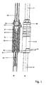
- FIG. 1 is a plug-in coupling of a lance, which is used for example in steel mills shown.
- the lance itself is well known to those skilled in the art and therefore not fully illustrated.
- the plug-in coupling connects the upper part 1 with the lower part 2 in a simple and secure manner.
- the upper part 1 has a coupling part 3 and the lower part 2 has a further coupling part 4.
- Upper part 1 and lower part 2, as well as the corresponding coupling parts 3, 4 are substantially tubular with a circular cross-section.
- the two coupling parts 3, 4 are connected by a bayonet joint.
- the bayonet lock is secured by a blocking device 5.
- the blocking device 5 is substantially formed as a tube which engages around the outside of the coupling part 3 with sufficient clearance so that it is longitudinally movable.
- the blocking device 5 drops down in the state shown in the drawing by itself, since it is designed as a slidable on the coupling part 3 tube. It falls on a stop 6, on which it rests and thus prevents loosening of the bayonet closure.
- the locking element 7 of the blocking device 5 is arranged on its inner side in the circumferential direction between the elevation 8 of the coupling part 4 of the lower part 2 and the opening / groove 9 of the coupling part 3 of the upper part 1 in the illustrated locking position.
- the coupling finally includes an electrical coupling 12, with which various signal cables 13, which are connected to the sensor, can be connected to a cable 14 for forwarding the measuring signals.
- an electrical coupling 12 with which various signal cables 13, which are connected to the sensor, can be connected to a cable 14 for forwarding the measuring signals.
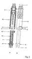
- FIG. 2 the clutch is shown in the released state.
- the various contact points 1 to 4 on the plug 12 'of the electric coupling 12 and correspondingly on the socket 12 "of the electrical 12 can be seen FIG. 2a )
- the opening / groove 9 is shown, which opens into a horizontal, circumferential to the axis of the plug-in extension 14.
- the survey 8 is passed to the coupling part 4 of the lower part 2 through the groove 9 of the coupling part 3 of the upper part 2. It presses against an arranged inside the blocking device 5 projection of the locking element 7.
- the blocking device 5 is pushed up and are the opening / groove 9 and the extension 14 completely free, so that after complete insertion of the coupling part 4 in the coupling part 3 both Coupling parts 3; 4 can be turned against each other.
- the elevation 8 moves in the extension 14 away from the opening / groove 9.
- the blocking device 5 automatically down, wherein the projection arranged in the interior of the locking element 7 prevents the survey 8 can be rotated back to the opening / groove 9.
- the two coupling parts 3; 4 are not detachable from each other in this state.
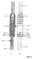
- FIG. 3 the position of the blocking device 5 is shown when Endriegeln the clutch.
- the blocking device 5 is pushed in the direction of the arrow 16.
- the possibility of movement of the survey 8 is released in the extension 14, since the locking element 7 has been pulled out of the recess 17 of the upper part 1.
- the lower part 2 with the coupling part 4 can be rotated in the circumferential direction of the arrow 18 and withdrawn against the direction of arrow 19 as soon as the elevation 8 is in the opening / groove 9.
- the representation in FIG. 4 essentially corresponds to the FIG. 3 , wherein also the electrical coupling 12 with the plug 12 'and the socket 12 "are shown in section.
Landscapes
- Engineering & Computer Science (AREA)
- Mechanical Engineering (AREA)
- General Engineering & Computer Science (AREA)
- Chemical & Material Sciences (AREA)
- Materials Engineering (AREA)
- Organic Chemistry (AREA)
- Metallurgy (AREA)
- Manufacturing & Machinery (AREA)
- Physics & Mathematics (AREA)
- General Physics & Mathematics (AREA)
- Investigating And Analyzing Materials By Characteristic Methods (AREA)
- Sampling And Sample Adjustment (AREA)
- Carbon Steel Or Casting Steel Manufacturing (AREA)
Applications Claiming Priority (1)
| Application Number | Priority Date | Filing Date | Title |
|---|---|---|---|
| DE102008013698A DE102008013698B4 (de) | 2008-03-11 | 2008-03-11 | Lanze zur Aufnahme eines Sensors oder Probennehmers für Metallschmelzen |
Publications (3)
| Publication Number | Publication Date |
|---|---|
| EP2100974A2 true EP2100974A2 (fr) | 2009-09-16 |
| EP2100974A3 EP2100974A3 (fr) | 2017-08-02 |
| EP2100974B1 EP2100974B1 (fr) | 2018-11-07 |
Family
ID=40843278
Family Applications (1)
| Application Number | Title | Priority Date | Filing Date |
|---|---|---|---|
| EP09001886.2A Active EP2100974B1 (fr) | 2008-03-11 | 2009-02-11 | Lance destinée à la réception d'un capteur ou d'un échantillonneur pour bains de fusion |
Country Status (4)
| Country | Link |
|---|---|
| US (1) | US7776254B2 (fr) |
| EP (1) | EP2100974B1 (fr) |
| DE (1) | DE102008013698B4 (fr) |
| RU (1) | RU2478926C2 (fr) |
Cited By (1)
| Publication number | Priority date | Publication date | Assignee | Title |
|---|---|---|---|---|
| WO2015104241A1 (fr) * | 2014-01-08 | 2015-07-16 | Vesuvius Group, Sa | Pyromètre optique |
Families Citing this family (3)
| Publication number | Priority date | Publication date | Assignee | Title |
|---|---|---|---|---|
| DE102010001669A1 (de) * | 2010-02-08 | 2011-08-11 | Siemens Aktiengesellschaft, 80333 | Vorrichtung zur Erfassung mindestens einer Messgröße an einem Ofen, sowie Ofen |
| UA108402C2 (xx) * | 2010-10-28 | 2015-04-27 | Безпровідний наконечник | |
| DE102013002389A1 (de) * | 2013-02-13 | 2014-08-14 | Minkon GmbH | Steckersystem, Messkopf, Kontaktstück, Verfahren zum Bestimmen einer Temperatur und einer elektromotorischen Kraft sowie Signalleitungsvorrichtung |
Citations (2)
| Publication number | Priority date | Publication date | Assignee | Title |
|---|---|---|---|---|
| DE3641225A1 (de) | 1985-12-04 | 1987-06-11 | Electro Nite | Verfahren und vorrichtung zur messung bzw. probenahme in metallschmelzen und dabei gebrauchte lanze |
| DE29805881U1 (de) | 1998-04-01 | 1998-06-25 | Preussag Stahl Ag, 31226 Peine | Meßlanze |
Family Cites Families (11)
| Publication number | Priority date | Publication date | Assignee | Title |
|---|---|---|---|---|
| US3369406A (en) * | 1964-12-29 | 1968-02-20 | Electro Nite | Molten material sampling apparatus and method |
| CA871239A (en) * | 1967-09-15 | 1971-05-18 | John K. Pargeter | Direct oxygen probe for liquid metals |
| DE3322556A1 (de) * | 1983-06-23 | 1985-01-10 | Didier-Werke Ag, 6200 Wiesbaden | Lanze zum einblasen fluidisierter stoffe in eine metallschmelze |
| SU1249378A1 (ru) * | 1984-07-05 | 1986-08-07 | Научно-исследовательский и опытно-конструкторский институт автоматизации черной металлургии | Устройство дл ввода датчиков в расплав |
| DE3729437A1 (de) * | 1987-05-06 | 1988-11-17 | Kloeckner Humboldt Deutz Ag | Vorrichtung zum ein- und/oder ausfuehren von brennerlanzen, probenehmern und dergl. durch die oeffnung eines behaelters |
| SU1608455A1 (ru) * | 1987-10-26 | 1990-11-23 | Э.А.Донской | Пробоотборный зонд |
| EP0372099B1 (fr) * | 1988-12-02 | 1993-05-05 | BEDA OXYGENTECHNIK ARMATUREN GmbH | Lance compacte ayant une sécurité contre la rotation des tubes |
| FR2668215B1 (fr) * | 1990-10-23 | 1993-07-30 | Cogema | Dispositif de raccordement a bauionnette et perche equipee d'un tel dispositif. |
| DE19707373C1 (de) * | 1997-02-25 | 1998-02-05 | Storz Karl Gmbh & Co | Bajonettkupplung zum lösbaren Verbinden zweier Rohrschaftinstrumente oder -instrumententeile |
| RU2308695C2 (ru) * | 2005-10-13 | 2007-10-20 | ООО "Нординкрафт-Сенсор" | Измерительный зонд для погружения в расплав металла |
| DE102006034737B4 (de) * | 2006-07-27 | 2009-11-26 | Westinghouse Electric Germany Gmbh | Vorrichtung zur Handhabung von Kleinbauteilen |
-
2008
- 2008-03-11 DE DE102008013698A patent/DE102008013698B4/de not_active Expired - Fee Related
-
2009
- 2009-02-11 EP EP09001886.2A patent/EP2100974B1/fr active Active
- 2009-03-10 RU RU2009108610/05A patent/RU2478926C2/ru active
- 2009-03-11 US US12/401,890 patent/US7776254B2/en active Active
Patent Citations (2)
| Publication number | Priority date | Publication date | Assignee | Title |
|---|---|---|---|---|
| DE3641225A1 (de) | 1985-12-04 | 1987-06-11 | Electro Nite | Verfahren und vorrichtung zur messung bzw. probenahme in metallschmelzen und dabei gebrauchte lanze |
| DE29805881U1 (de) | 1998-04-01 | 1998-06-25 | Preussag Stahl Ag, 31226 Peine | Meßlanze |
Cited By (2)
| Publication number | Priority date | Publication date | Assignee | Title |
|---|---|---|---|---|
| WO2015104241A1 (fr) * | 2014-01-08 | 2015-07-16 | Vesuvius Group, Sa | Pyromètre optique |
| US10126174B2 (en) | 2014-01-08 | 2018-11-13 | Vesuvius Group, S.A. | Optical pyrometer |
Also Published As
| Publication number | Publication date |
|---|---|
| EP2100974A3 (fr) | 2017-08-02 |
| DE102008013698B4 (de) | 2010-04-29 |
| RU2009108610A (ru) | 2010-09-20 |
| US7776254B2 (en) | 2010-08-17 |
| RU2478926C2 (ru) | 2013-04-10 |
| DE102008013698A1 (de) | 2009-10-08 |
| EP2100974B1 (fr) | 2018-11-07 |
| US20090230597A1 (en) | 2009-09-17 |
Similar Documents
| Publication | Publication Date | Title |
|---|---|---|
| EP2636758B1 (fr) | Support de lance avec une sécurité pour lances à oxygène non droites, en particulier courbées | |
| EP2100974B1 (fr) | Lance destinée à la réception d'un capteur ou d'un échantillonneur pour bains de fusion | |
| DE4401758C1 (de) | Selbstfahrendes Fahrzeug zur Fernsehinspektion, insbesondere der Abzweigleitungen von einem im Erdreich verlegten Sammelkanal aus | |
| DE4323866A1 (de) | Abstreifhilfe für auf einem Führungsdraht angeordnete spiralförmige Implantate | |
| DE102018105190A1 (de) | Endoskop-Rohr | |
| EP0949711A2 (fr) | Connecteur de câble | |
| WO2008122416A2 (fr) | Accouplement de train de tiges à élément sacrificiel | |
| DE29909215U1 (de) | Halterung für Funktelefone | |
| DE202007016427U1 (de) | Rohrinspektionseinheit | |
| DE102009050856A1 (de) | System zur Kanalinspektion | |
| DE102020106793A1 (de) | Filterkopf sowie Erweiterungsset für einen Filterkopf | |
| EP2186953A2 (fr) | Siphon compact et système constitué d'un siphon compact et d'un système anti-débordement | |
| EP2071325A2 (fr) | Armature de changement immergée pour un capteur | |
| DE102017212536A1 (de) | Werkzeug zum Heranführen einer flexiblen Leitung an ein Anschlussteil | |
| EP2466604B1 (fr) | Unité d'entraînement pour le fonctionnement d'un interrupteur d'une installation de commutation à moyenne ou haute tension | |
| DE102013103835A1 (de) | Flüssigkeits-Dosiervorrichtung | |
| DE102013201603C5 (de) | Vorrichtung und Verfahren zum Zuführen von Kleinteilen an Einbauorten | |
| EP2659990A2 (fr) | Dispositif d'inspection et/ou d'assainissement de conduites | |
| DE102007015696A1 (de) | Kabelschuh | |
| DE10259610A1 (de) | Schachtbauwerk mit Merkhilfe für Revisionsdeckel | |
| CH683646A5 (de) | Steckverbindung für Lichtwellenleiter. | |
| DE19956927C1 (de) | Werkzeug zum Montieren einer Sicherungsklammer | |
| DE19921275B4 (de) | Einbaudose für die Betonbauinstallation | |
| DE19906545C2 (de) | Vorrichtung zur Anlenkung eines mechanischen Betätigungszuges | |
| DE102018100025A1 (de) | Vorrichtung zum Überführen einer Leitung zwischen einem eingefahrenen Zustand und einem ausgefahrenen Zustand sowie entsprechendes System, entsprechende Verwendung und entsprechendes Verfahren |
Legal Events
| Date | Code | Title | Description |
|---|---|---|---|
| PUAI | Public reference made under article 153(3) epc to a published international application that has entered the european phase |
Free format text: ORIGINAL CODE: 0009012 |
|
| 17P | Request for examination filed |
Effective date: 20090220 |
|
| AK | Designated contracting states |
Kind code of ref document: A2 Designated state(s): AT BE BG CH CY CZ DE DK EE ES FI FR GB GR HR HU IE IS IT LI LT LU LV MC MK MT NL NO PL PT RO SE SI SK TR |
|
| AX | Request for extension of the european patent |
Extension state: AL BA RS |
|
| PUAL | Search report despatched |
Free format text: ORIGINAL CODE: 0009013 |
|
| AK | Designated contracting states |
Kind code of ref document: A3 Designated state(s): AT BE BG CH CY CZ DE DK EE ES FI FR GB GR HR HU IE IS IT LI LT LU LV MC MK MT NL NO PL PT RO SE SI SK TR |
|
| AX | Request for extension of the european patent |
Extension state: AL BA RS |
|
| RIC1 | Information provided on ipc code assigned before grant |
Ipc: G01K 1/12 20060101ALI20170629BHEP Ipc: G01K 1/00 20060101ALI20170629BHEP Ipc: F27D 19/00 20060101ALI20170629BHEP Ipc: G01K 1/14 20060101ALI20170629BHEP Ipc: G01K 13/12 20060101ALI20170629BHEP Ipc: C21C 5/46 20060101AFI20170629BHEP Ipc: F27D 21/00 20060101ALI20170629BHEP |
|
| AKX | Designation fees paid |
Designated state(s): AT BE BG CH CY CZ DE DK EE ES FI FR GB GR HR HU IE IS IT LI LT LU LV MC MK MT NL NO PL PT RO SE SI SK TR |
|
| AXX | Extension fees paid |
Extension state: BA Extension state: RS Extension state: AL |
|
| GRAP | Despatch of communication of intention to grant a patent |
Free format text: ORIGINAL CODE: EPIDOSNIGR1 |
|
| STAA | Information on the status of an ep patent application or granted ep patent |
Free format text: STATUS: GRANT OF PATENT IS INTENDED |
|
| INTG | Intention to grant announced |
Effective date: 20180807 |
|
| GRAS | Grant fee paid |
Free format text: ORIGINAL CODE: EPIDOSNIGR3 |
|
| GRAA | (expected) grant |
Free format text: ORIGINAL CODE: 0009210 |
|
| STAA | Information on the status of an ep patent application or granted ep patent |
Free format text: STATUS: THE PATENT HAS BEEN GRANTED |
|
| AK | Designated contracting states |
Kind code of ref document: B1 Designated state(s): AT BE BG CH CY CZ DE DK EE ES FI FR GB GR HR HU IE IS IT LI LT LU LV MC MK MT NL NO PL PT RO SE SI SK TR |
|
| REG | Reference to a national code |
Ref country code: GB Ref legal event code: FG4D Free format text: NOT ENGLISH |
|
| REG | Reference to a national code |
Ref country code: CH Ref legal event code: EP Ref country code: AT Ref legal event code: REF Ref document number: 1062121 Country of ref document: AT Kind code of ref document: T Effective date: 20181115 |
|
| REG | Reference to a national code |
Ref country code: DE Ref legal event code: R096 Ref document number: 502009015420 Country of ref document: DE |
|
| REG | Reference to a national code |
Ref country code: IE Ref legal event code: FG4D Free format text: LANGUAGE OF EP DOCUMENT: GERMAN |
|
| REG | Reference to a national code |
Ref country code: NL Ref legal event code: MP Effective date: 20181107 |
|
| REG | Reference to a national code |
Ref country code: LT Ref legal event code: MG4D |
|
| PG25 | Lapsed in a contracting state [announced via postgrant information from national office to epo] |
Ref country code: IS Free format text: LAPSE BECAUSE OF FAILURE TO SUBMIT A TRANSLATION OF THE DESCRIPTION OR TO PAY THE FEE WITHIN THE PRESCRIBED TIME-LIMIT Effective date: 20190307 Ref country code: FI Free format text: LAPSE BECAUSE OF FAILURE TO SUBMIT A TRANSLATION OF THE DESCRIPTION OR TO PAY THE FEE WITHIN THE PRESCRIBED TIME-LIMIT Effective date: 20181107 Ref country code: LV Free format text: LAPSE BECAUSE OF FAILURE TO SUBMIT A TRANSLATION OF THE DESCRIPTION OR TO PAY THE FEE WITHIN THE PRESCRIBED TIME-LIMIT Effective date: 20181107 Ref country code: HR Free format text: LAPSE BECAUSE OF FAILURE TO SUBMIT A TRANSLATION OF THE DESCRIPTION OR TO PAY THE FEE WITHIN THE PRESCRIBED TIME-LIMIT Effective date: 20181107 Ref country code: NO Free format text: LAPSE BECAUSE OF FAILURE TO SUBMIT A TRANSLATION OF THE DESCRIPTION OR TO PAY THE FEE WITHIN THE PRESCRIBED TIME-LIMIT Effective date: 20190207 Ref country code: BG Free format text: LAPSE BECAUSE OF FAILURE TO SUBMIT A TRANSLATION OF THE DESCRIPTION OR TO PAY THE FEE WITHIN THE PRESCRIBED TIME-LIMIT Effective date: 20190207 Ref country code: ES Free format text: LAPSE BECAUSE OF FAILURE TO SUBMIT A TRANSLATION OF THE DESCRIPTION OR TO PAY THE FEE WITHIN THE PRESCRIBED TIME-LIMIT Effective date: 20181107 Ref country code: LT Free format text: LAPSE BECAUSE OF FAILURE TO SUBMIT A TRANSLATION OF THE DESCRIPTION OR TO PAY THE FEE WITHIN THE PRESCRIBED TIME-LIMIT Effective date: 20181107 |
|
| PG25 | Lapsed in a contracting state [announced via postgrant information from national office to epo] |
Ref country code: PT Free format text: LAPSE BECAUSE OF FAILURE TO SUBMIT A TRANSLATION OF THE DESCRIPTION OR TO PAY THE FEE WITHIN THE PRESCRIBED TIME-LIMIT Effective date: 20190307 Ref country code: NL Free format text: LAPSE BECAUSE OF FAILURE TO SUBMIT A TRANSLATION OF THE DESCRIPTION OR TO PAY THE FEE WITHIN THE PRESCRIBED TIME-LIMIT Effective date: 20181107 Ref country code: GR Free format text: LAPSE BECAUSE OF FAILURE TO SUBMIT A TRANSLATION OF THE DESCRIPTION OR TO PAY THE FEE WITHIN THE PRESCRIBED TIME-LIMIT Effective date: 20190208 Ref country code: SE Free format text: LAPSE BECAUSE OF FAILURE TO SUBMIT A TRANSLATION OF THE DESCRIPTION OR TO PAY THE FEE WITHIN THE PRESCRIBED TIME-LIMIT Effective date: 20181107 |
|
| PG25 | Lapsed in a contracting state [announced via postgrant information from national office to epo] |
Ref country code: IT Free format text: LAPSE BECAUSE OF FAILURE TO SUBMIT A TRANSLATION OF THE DESCRIPTION OR TO PAY THE FEE WITHIN THE PRESCRIBED TIME-LIMIT Effective date: 20181107 Ref country code: CZ Free format text: LAPSE BECAUSE OF FAILURE TO SUBMIT A TRANSLATION OF THE DESCRIPTION OR TO PAY THE FEE WITHIN THE PRESCRIBED TIME-LIMIT Effective date: 20181107 Ref country code: DK Free format text: LAPSE BECAUSE OF FAILURE TO SUBMIT A TRANSLATION OF THE DESCRIPTION OR TO PAY THE FEE WITHIN THE PRESCRIBED TIME-LIMIT Effective date: 20181107 Ref country code: PL Free format text: LAPSE BECAUSE OF FAILURE TO SUBMIT A TRANSLATION OF THE DESCRIPTION OR TO PAY THE FEE WITHIN THE PRESCRIBED TIME-LIMIT Effective date: 20181107 |
|
| REG | Reference to a national code |
Ref country code: DE Ref legal event code: R097 Ref document number: 502009015420 Country of ref document: DE |
|
| PG25 | Lapsed in a contracting state [announced via postgrant information from national office to epo] |
Ref country code: EE Free format text: LAPSE BECAUSE OF FAILURE TO SUBMIT A TRANSLATION OF THE DESCRIPTION OR TO PAY THE FEE WITHIN THE PRESCRIBED TIME-LIMIT Effective date: 20181107 Ref country code: RO Free format text: LAPSE BECAUSE OF FAILURE TO SUBMIT A TRANSLATION OF THE DESCRIPTION OR TO PAY THE FEE WITHIN THE PRESCRIBED TIME-LIMIT Effective date: 20181107 Ref country code: SK Free format text: LAPSE BECAUSE OF FAILURE TO SUBMIT A TRANSLATION OF THE DESCRIPTION OR TO PAY THE FEE WITHIN THE PRESCRIBED TIME-LIMIT Effective date: 20181107 |
|
| PLBE | No opposition filed within time limit |
Free format text: ORIGINAL CODE: 0009261 |
|
| STAA | Information on the status of an ep patent application or granted ep patent |
Free format text: STATUS: NO OPPOSITION FILED WITHIN TIME LIMIT |
|
| REG | Reference to a national code |
Ref country code: CH Ref legal event code: PL |
|
| 26N | No opposition filed |
Effective date: 20190808 |
|
| GBPC | Gb: european patent ceased through non-payment of renewal fee |
Effective date: 20190211 |
|
| PG25 | Lapsed in a contracting state [announced via postgrant information from national office to epo] |
Ref country code: MC Free format text: LAPSE BECAUSE OF FAILURE TO SUBMIT A TRANSLATION OF THE DESCRIPTION OR TO PAY THE FEE WITHIN THE PRESCRIBED TIME-LIMIT Effective date: 20181107 Ref country code: LU Free format text: LAPSE BECAUSE OF NON-PAYMENT OF DUE FEES Effective date: 20190211 Ref country code: SI Free format text: LAPSE BECAUSE OF FAILURE TO SUBMIT A TRANSLATION OF THE DESCRIPTION OR TO PAY THE FEE WITHIN THE PRESCRIBED TIME-LIMIT Effective date: 20181107 |
|
| REG | Reference to a national code |
Ref country code: DE Ref legal event code: R082 Ref document number: 502009015420 Country of ref document: DE Representative=s name: BRAND, NORMEN, DR. RER. NAT., DE Ref country code: DE Ref legal event code: R082 Ref document number: 502009015420 Country of ref document: DE Representative=s name: BRAND, NORMEN, DIPL.-CHEM. UNIV. DR. RER. NAT., DE |
|
| REG | Reference to a national code |
Ref country code: BE Ref legal event code: MM Effective date: 20190228 |
|
| REG | Reference to a national code |
Ref country code: IE Ref legal event code: MM4A |
|
| PG25 | Lapsed in a contracting state [announced via postgrant information from national office to epo] |
Ref country code: LI Free format text: LAPSE BECAUSE OF NON-PAYMENT OF DUE FEES Effective date: 20190228 Ref country code: CH Free format text: LAPSE BECAUSE OF NON-PAYMENT OF DUE FEES Effective date: 20190228 |
|
| PG25 | Lapsed in a contracting state [announced via postgrant information from national office to epo] |
Ref country code: IE Free format text: LAPSE BECAUSE OF NON-PAYMENT OF DUE FEES Effective date: 20190211 Ref country code: GB Free format text: LAPSE BECAUSE OF NON-PAYMENT OF DUE FEES Effective date: 20190211 |
|
| PG25 | Lapsed in a contracting state [announced via postgrant information from national office to epo] |
Ref country code: BE Free format text: LAPSE BECAUSE OF NON-PAYMENT OF DUE FEES Effective date: 20190228 |
|
| PG25 | Lapsed in a contracting state [announced via postgrant information from national office to epo] |
Ref country code: TR Free format text: LAPSE BECAUSE OF FAILURE TO SUBMIT A TRANSLATION OF THE DESCRIPTION OR TO PAY THE FEE WITHIN THE PRESCRIBED TIME-LIMIT Effective date: 20181107 |
|
| REG | Reference to a national code |
Ref country code: AT Ref legal event code: MM01 Ref document number: 1062121 Country of ref document: AT Kind code of ref document: T Effective date: 20190211 |
|
| PG25 | Lapsed in a contracting state [announced via postgrant information from national office to epo] |
Ref country code: AT Free format text: LAPSE BECAUSE OF NON-PAYMENT OF DUE FEES Effective date: 20190211 |
|
| PG25 | Lapsed in a contracting state [announced via postgrant information from national office to epo] |
Ref country code: MT Free format text: LAPSE BECAUSE OF FAILURE TO SUBMIT A TRANSLATION OF THE DESCRIPTION OR TO PAY THE FEE WITHIN THE PRESCRIBED TIME-LIMIT Effective date: 20181107 |
|
| PG25 | Lapsed in a contracting state [announced via postgrant information from national office to epo] |
Ref country code: CY Free format text: LAPSE BECAUSE OF FAILURE TO SUBMIT A TRANSLATION OF THE DESCRIPTION OR TO PAY THE FEE WITHIN THE PRESCRIBED TIME-LIMIT Effective date: 20181107 |
|
| PG25 | Lapsed in a contracting state [announced via postgrant information from national office to epo] |
Ref country code: HU Free format text: LAPSE BECAUSE OF FAILURE TO SUBMIT A TRANSLATION OF THE DESCRIPTION OR TO PAY THE FEE WITHIN THE PRESCRIBED TIME-LIMIT; INVALID AB INITIO Effective date: 20090211 |
|
| PG25 | Lapsed in a contracting state [announced via postgrant information from national office to epo] |
Ref country code: MK Free format text: LAPSE BECAUSE OF FAILURE TO SUBMIT A TRANSLATION OF THE DESCRIPTION OR TO PAY THE FEE WITHIN THE PRESCRIBED TIME-LIMIT Effective date: 20181107 |
|
| P01 | Opt-out of the competence of the unified patent court (upc) registered |
Effective date: 20230530 |
|
| PGFP | Annual fee paid to national office [announced via postgrant information from national office to epo] |
Ref country code: DE Payment date: 20260218 Year of fee payment: 18 |
|
| PGFP | Annual fee paid to national office [announced via postgrant information from national office to epo] |
Ref country code: FR Payment date: 20260218 Year of fee payment: 18 |