EP2466604B1 - Unité d'entraînement pour le fonctionnement d'un interrupteur d'une installation de commutation à moyenne ou haute tension - Google Patents
Unité d'entraînement pour le fonctionnement d'un interrupteur d'une installation de commutation à moyenne ou haute tension Download PDFInfo
- Publication number
- EP2466604B1 EP2466604B1 EP11191860.3A EP11191860A EP2466604B1 EP 2466604 B1 EP2466604 B1 EP 2466604B1 EP 11191860 A EP11191860 A EP 11191860A EP 2466604 B1 EP2466604 B1 EP 2466604B1
- Authority
- EP
- European Patent Office
- Prior art keywords
- drive unit
- switch
- drive
- plug
- guide
- Prior art date
- Legal status (The legal status is an assumption and is not a legal conclusion. Google has not performed a legal analysis and makes no representation as to the accuracy of the status listed.)
- Active
Links
Images


Classifications
-
- H—ELECTRICITY
- H01—ELECTRIC ELEMENTS
- H01H—ELECTRIC SWITCHES; RELAYS; SELECTORS; EMERGENCY PROTECTIVE DEVICES
- H01H33/00—High-tension or heavy-current switches with arc-extinguishing or arc-preventing means
- H01H33/02—Details
- H01H33/28—Power arrangements internal to the switch for operating the driving mechanism
- H01H33/36—Power arrangements internal to the switch for operating the driving mechanism using dynamo-electric motor
-
- H—ELECTRICITY
- H01—ELECTRIC ELEMENTS
- H01H—ELECTRIC SWITCHES; RELAYS; SELECTORS; EMERGENCY PROTECTIVE DEVICES
- H01H33/00—High-tension or heavy-current switches with arc-extinguishing or arc-preventing means
- H01H33/02—Details
- H01H33/42—Driving mechanisms
-
- H—ELECTRICITY
- H02—GENERATION; CONVERSION OR DISTRIBUTION OF ELECTRIC POWER
- H02B—BOARDS, SUBSTATIONS OR SWITCHING ARRANGEMENTS FOR THE SUPPLY OR DISTRIBUTION OF ELECTRIC POWER
- H02B13/00—Arrangement of switchgear in which switches are enclosed in, or structurally associated with, a casing, e.g. cubicle
- H02B13/02—Arrangement of switchgear in which switches are enclosed in, or structurally associated with, a casing, e.g. cubicle with metal casing
- H02B13/035—Gas-insulated switchgear
Definitions
- the present invention relates to a drive unit for operating a switch of a medium or high voltage switchgear and a switchgear with such a drive unit, in particular a gas-insulated switchgear.
- Such switches typically have a metallic housing, to which the drive unit required for moving the switching element, together with the switch drive, is fastened.
- Switches are understood below to be auxiliary switches, such as normally-open switches, isolating switches or switch-on earth switches and the like, but not circuit-breakers, such as gas-insulated circuit breakers with an arc extinguishing device and the like.
- the substation points once large dimensions of several meters, with the switches in different positions - in other words, geometric locations - in the substation are attached.
- the switches are also aligned differently with each other.
- the drive unit is typically replaced by a technician, with the switch itself possibly remaining installed in the substation. Depending on the size of the substation, especially the latter can be associated with considerable effort.
- the drive unit which with at least one switch of a medium or high voltage switchgear for transferring at least one switching element of the at least one switch from a first position can be connected in a second position
- the drive unit which with at least one switch of a medium or high voltage switchgear for transferring at least one switching element of the at least one switch from a first position can be connected in a second position
- the term transferring the movable switching element of a switch from a first position to a second position is understood to mean a movement, for example in the form of a linear displacement or a rotation.
- the drive unit has a first guide element, while a switch drive of the drive unit has the electric motor and the electrical interface and a second guide element.
- the switch drive interacts with the first guide element via the second guide element in such a way that the switch drive can be inserted into the drive unit and pulled out of the drive unit.
- the switch drive has a mechanical clutch for delivering a drive force that can be generated via the electric motor to a switch that can be arranged spatially remotely from the drive unit.
- the drive unit can be arranged spatially away from the switch, for example, systems can be produced, in which the actual switch a substation, such as a gas-insulated switchgear can remain at their optimal positions in the switchgear, while the drive unit arranged to move in the switch Switching element is arranged in a user-friendly, easily accessible place.
- the drive unit directly on the operating gear of a switchgear, which can achieve ideal accessibility when installed.
- control or monitoring work has already been carried out for a long time by the operating gear, for example on a control cabinet.
- the power transmission of the switch drive of the drive unit to be moved to the switching element of spatially depending on the embodiment several meters away arranged switching element of a switch, for example via a hydraulic line or a mechanical shaft.
- the drive unit is correspondingly a hydraulic drive unit which, for example, comprises a pump for supplying hydraulic oil.
- the power transmission takes place hydraulicly, this is possible for example via a mechanical connection in the form of a mechanical shaft or a transmission which connects the drive unit with the switching element to be moved.
- the mechanical power transmission via a flexible shaft - also called flexible shaft - takes place, additional advantages in terms of recording mounting tolerances and the more versatile installation position of switches can be achieved, which are arranged at relatively hard to reach places in the switchgear.
- this has in the case of mechanical power transmission, for example, an electric motor as the actual drive means.
- the plug-in drive which can be plugged into the drive unit and can be pulled out of the drive unit allows a technician in a very short time to replace a defective drive unit according to the invention with a functional drive unit according to the invention.
- a technician in known systems first had to reach the switch unit located somewhere in the switchgear before he could see the drive unit with switch drive attached to the housing or even integrated into the housing of the switch and replace it if necessary. For example, if the switch drive is now in the operating gear, a technician may have to leave without the service gear and get to the drive unit and thus the switch drive in the shortest possible time.
- the mechanical coupling further promotes interchangeability of interchangeability by interfacing with the power transmission means, such as the mechanical shaft.
- the power transmission means such as the mechanical shaft.
- this allows a coupling or decoupling of the power transmission means, without the need for a separate manipulation by the technician is required.
- the coupling can make a considerable contribution to facilitating interchangeability of the drive unit.
- a coupling with a form fit wherein the mechanical shaft, for example, has a coupling portion with a receiving opening with a hexagonal interior section, while the switch drive for power output has a correspondingly shaped coupling portion with a hexagonal bolt portion.
- the term "operating the switchgear” is understood below, inter alia, controlling, regulating, measuring, monitoring, supplying the switch with power et cetera.
- the means required for this purpose are, for example, power transformers, units for evaluating sensor data, gas density monitors, temperature sensors, units for evaluating end position data from the switch, units for evaluating position data of the switching element in the switch and the like.
- the drive unit can be, for example reach by a linear insertion of two oppositely shaped guides.
- they may be coated as required, for example with polytetrafluoroethylene, or even be made of a material combination with a low sliding resistance, such as nylon - metal or include these.
- embodiments are possible which has a roller mechanism similar to that of a modern drawer.
- a suitable coding means can be used.
- This coding means may be part of the guides or be independent of the guides. In the former case, a coding about the dimensioning of the guides can be achieved. In the latter case, a coding can be achieved, for example, with a pin-socket-type interlock which, depending on the pin and / or socket arrangement, prevents complete insertion of a "false" switch drive into the switch drive receptacle.
- connection can be achieved, for example, by riveting a nylon strip onto the base body.
- an embodiment of the switch drive can have mechanical operating means, via which operating means the switch drive can be moved into the drive unit plugged state is alternatively operated by hand.
- Representative examples of a large number of possible operating means are, for example, a shaft end connected to a transmission with an external polygon for attaching a fork wrench or socket wrench or a winch drive. In the latter case, the hand crank for safety reasons for normal operation can be removed from the switch drive.
- the arrangement of an alternative manual drive is particularly advantageous if the drive unit with the switch drive operator side ergonomic as ideally as possible for an operator / technician is accessible.
- embodiments of the drive unit can be realized in which the switch drive is connected to a arranged in the drive unit or in the switching cabinet switch position display. Moreover, embodiments are also feasible, in which the switch drive itself has a switching position display, with which a switching position of the switching element can be displayed during operation of the drive unit or the switchgear.
- Geometrically particularly simple drive units can be realized if the second guide element is at least partially integrated into the main body. Depending on the embodiment, this is approximately the case when the base body is made of sheet metal, which is either flat or curved. By bending over the sheet, even more demanding guides can be realized cost-effectively, for example with a Z-shaped, second guide element.
- the electrical interface can be designed as an electrical plug connection with at least one plug and a socket.
- the plug or socket is lockable, for example, with the body. This can for example by a detachable connection by means of a screw with a union nut or the like or a plug-in bayonet connection be achieved.
- non-destructively releasable compound may be mentioned at this point a clip connection or an adhesive bond.
- the connector defines a plug-in axis which extends transversely to the guide axis, in particular extends at right angles to the guide axis 21.
- a likewise designed as a drawer-like drawer switch drive can be realized in which the connector defines a plug-in axis, which extends in the direction of the guide axis that automatically adjusts when plugging the switch drive in the drive unit, an electrical plug connection between the plug and socket.
- This embodiment is advantageous in that, when the switch drive is correctly inserted into the first guide, a faultless electrical contacting can be effected automatically.
- Such an embodiment is also foolproof. If the contact forces required for contacting should exceed a threshold value, a reliable application of the required force can be ensured by the arrangement of a contacting aid.
- a contacting aid can be, for example, a screw connection acting in the direction of the guide axis between the switch drive and the drive unit with the first guide element.
- An alternative contacting aid can be achieved by a knee joint clamping device acting in the direction of the guide axis between the switch drive and the drive unit.
- a knee joint clamping device acting in the direction of the guide axis between the switch drive and the drive unit.
- at least one centering element for example a centering mandrel, can be provided.
- the switch drive also includes auxiliary contacts for detecting a switch position of the drivable switch.
- this detection of a switch position via a position detection of the motor shaft or an intermediate gear, for example via a rotation angle detection.
- auxiliary contacts for example, a plug connector can be dispensed with in comparison to known drive units.
- the switch drive in the inserted state is mechanically connectable to the drive unit, in embodiments mechanically lockable.
- a connection can be, for example, a screw connection acting in the direction of the guide axis between the switch drive and the drive unit with the first guide element.
- the switch drive is sealed in its inserted state in the drive unit, for example by means of a seal.
- the locking can be ensured equal combined with the above-mentioned contacting aid.
- this connection or locking for example, be realized as arranged on the switch drive or on the drive unit side toggle clamp.
- the drive unit is connected to a switch for transferring a switching element of the switch from a first position to a second position, wherein the drive unit is arranged spatially away from the switch.
- the term "spatially arranged away from the switch” is understood to mean a drive unit which does not rest on the switch or the switch housing itself is applied, but for example in one of several meters away switching cabinet of the switchgear.
- the switchgear is designed as a gas-insulated switchgear with a drive unit according to the abovementioned embodiments, and the switch drive has a mechanical coupling for delivering a torque that can be generated via the electric motor via a mechanical shaft, in particular a flexible shaft, to the switch, further advantages result in terms of the degree of freedom in the switchgear design.
- GIS gas-insulated switchgear
- DTB dead tank breakers
- LTB live tank breakers
- AIS air-insulated switchgear
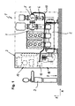
- FIG. 1 illustrated first embodiment of an inventive gas-insulated switchgear 1 with a horizontally extending (X) circuit breaker 2 and a frontally arranged to combined drive and control cabinet 3.
- the switchgear is arranged within a direction indicated by a dash-dotted line space and includes at least one gas-insulated switch 4 with at least one movable switching element 5.
- the movable switching element 5 interrupts or connects a first conductor section 6 with a second conductor section 7 of the switchgear 1.
- the conductor sections 6, 7 and the interior of the switch are shown only stylized.
- an operating passage 8 extending in the Y-direction is arranged for an operator or technician 9.
- the drive and control cabinet 3 comprises a control unit 13 for controlling and regulating the switchgear, as well as a drive unit 10 (both shown in phantom).
- the drive unit 10 is used inter alia for transferring the at least one switching element 5 of the at least one switch 4 from a first position to a second position.
- the drive unit 10 has a switch drive 15, which is arranged spatially away from the actual switch 4, close to the operation gear 8.
- the switch drive 15 includes an electric motor 22 (see, for example Fig. 2 to 4 ), whose driving force acts here on a flexible mechanical shaft 16 on the movable switching element 5.
- a switchgear for example a gas-insulated substation, can have a multiplicity of switches and correspondingly a large number of switch drives.
- each of the two switch drives 15 represented here in the manner of a drawer can be inserted into the drive unit 10 and pulled out of the drive unit 10 (see double arrow in FIG FIG. 2 ).
- the drive unit 10 has on the cabinet side at least one first guide element 17 for interacting with at least one second switch drive-side second guide element 18.
- possible embodiments for the guidance becomes on the occasion of the description to the FIGS. 5 and 6 later discussed in more detail.
- drive unit 15 are associated with each switch drive 15, two first guide elements 17 in the form of U-shaped profiles, which receive a two second guide elements 18 having base body 19 of the switch drive 15 guided laterally and so form a guide axis 21, along which the switch drive 15 is movable.
- the second guide elements 18 are fully integrated in the tinny base body 19 and formed by its longitudinal edges 20.
- the switch drive 15 is shown in a nearly completely pulled out of the drive unit 10 state, while the switch drive 15 is shown to the right of it in the drive unit 10 fully inserted state (operating state), in which the switch drive 15 with the movable shaft 16 is operatively connected.
- connectors 24 In this case, defines the orientation of the connectors 24, of which in FIG. 2
- the thru axle 25 extends transversely to the guide axis 21 and defines the required direction of movement of the operator 9 for electrically contacting or decontacting the switching drive with terminals, for example with the control unit coming connecting cables.
- the electrical interface 23 is below a window-like connection opening 26 of the likewise formed as a separate cabinet drive unit 10 so that the operator 9 can make the electrical contacting or decontacting of the connectors conveniently.
- the drive unit 10 is shown without cover side cover to illustrate the interchangeability of the switch actuators 15.
- the motor 22 is connected to the flexible shaft 16 via a positive mechanical coupling 27.
- the switch drive 15 additionally has one or more gear stages between the engine 22 and the clutch 27.
- the mechanical coupling 27 of the switch drive 15 together with a (not shown in the drawing) coupling element on the connection side of the flexible shaft 16 forms a positive, pluggable coupling.
- the switch drive 15 auxiliary contacts 28. Since a mechanical shaft 16 is a complete mechanical transmission chain between electric motor 22 and switching element 5, the position detection is so reliable realized.
- the switch drive 15 has an integrated switch position indicator 31, with which during operation of the drive unit 10 and the switchgear 1, the switching position of the switching element 5 ergonomically ideal for the reader.
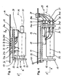
- FIG. 3 shows a simplified sectional view of the fully inserted into the drive unit 10 or inserted switch drive 15 of a first embodiment transverse to a first plane 29 of FIG. 2 , seen in the direction of the double arrow.
- the base body 19 is a sheet metal body which is angled away from the operation gear 8.
- the basic body can alternatively also be assembled from a plurality of structure-forming elements or else configured as a cast body.
- Both the electric motor 22, and the auxiliary contacts 28 are fixedly connected to the main body 19 of the switch drive 15.
- the clutch 27 attaches to the electric motor 22.
- the connectable to the clutch 27 flexible shaft 16 is shown only stylized as a dotted line.
- the electrical interface 23 is user-friendly accessible through the connection opening 26 of the cabinet-like drive unit 10 and includes the sockets 24a, 24b, 24c, 24d, 24e formed parts of the aligned in the direction of the plug-in axis 25 plug contact connection.
- These sockets 24a, 24b, 24c, 24d, 24e are fixedly connected to the main body 19 via a detachable screw connection and via electrical lines 30 to the motor and / or the auxiliary contacts 28 connected.
- embodiments of the switch drive 15 may have, depending on requirements, further electrical elements such as, for example, series resistors and / or auxiliary switches.
- connection opening 26 The mating to the sockets 24 a, 24 b, 24 c, 24 d, 24 e plug are passed through the connection opening 26 and are in FIG. 3 Not shown.
- the switch actuator 15 is for secure attachment via a further screw 33 fixed to the mechanical structure of the drive unit 10 can be connected and / or locked.
- FIG. 4 shown alternative second embodiment of the switch actuator 15 is in the same representation as in FIG. 3 presented to illustrate the differences more clearly. Due to the similarity of the second embodiment of the switch drive 15 for in FIG. 3 shown first embodiment of the switch drive 15 will be discussed in more detail below only on the differences of the second embodiment of the switch drive 15 with respect to the first embodiment. Accordingly, identical or identically acting parts are also provided with identical reference numerals.
- the main body 19 of the second embodiment of the switch drive 15 has a U-shaped cross-section as seen in the Y direction.
- the sockets 24a, 24b, 24c, 24d of the electrical interface 23 are arranged at an end of the main body 19 facing away from the operating gear 8 on an outer side of the rear profile leg of the body 19 and define a plug-in axis 25 which extends in the same direction as through the guide elements 17, 18 defined guide axis 21st
- the plugs are 34a, 34b, 34c, 34c fixedly connected via a rigid connection geometry in the form of a support 35 with the mechanical structure of the drive unit 10, and the cover plate 36 thereof.
- the plugs 34a, 34b, 34c, 34c are in turn connected via connecting leads 37 to further plug contacts 38, which can be connected from above the cover plate 36 by the operator to connection cables coming from the control cabinet.
- the other plug contacts 38 are the same as the sockets 24a, 24b, 24c, 24d.
- the switch drive 15 is held firmly and reliably in its fully retracted position in the direction of the guide axis 21 via a drive unit side arranged toggle clamp 41.
- FIG. 5 shows a first embodiment of a guide in a simplified sectional view along a in FIG. 3 plane marked VV.
- the first guide element 17 comprises two first guide profiles 39 made of extruded light metal.
- Each guide profile 39 has a slot-shaped receiving area 40, in which the second guide element 18 forming longitudinal edges 20 of the base body 19 are guided in the YZ direction and only a pushing in and pulling out of a rectangular cross-section having base body 19 in the X-direction extending guide axis 21 allow.
- a arranged between the base body 19 and the cover plate 36 space is dimensioned according to the space requirements of the sockets 24a, 24b, 24c, 24d, 24e.
- FIG. 6 an alternative second guide of a second embodiment with an alternative first guide member 17 and an alternative second guide member 18 shown. Due to the similarity of the second embodiment of the guide to in FIG. 5 shown first embodiment will now be discussed in more detail only on the differences of the second embodiment with respect to the first embodiment. Accordingly, identical or identically acting parts are also provided with identical reference numerals.
- the second embodiment of the main body 19 has a hat-shaped cross-section, with one end section of the main body 19 each extending in the Y direction. These end sections form the actual second guide element 18.
- the first guide member 17 of the second embodiment has a Z-shaped cross section in the YZ direction.
Landscapes
- Engineering & Computer Science (AREA)
- Power Engineering (AREA)
- Operating, Guiding And Securing Of Roll- Type Closing Members (AREA)
- Driving Mechanisms And Operating Circuits Of Arc-Extinguishing High-Tension Switches (AREA)
- Mechanisms For Operating Contacts (AREA)
- Switch Cases, Indication, And Locking (AREA)
Claims (10)
- Unité d'entraînement (10), qui peut être reliée à au moins un commutateur (4) d'une installation de commutation de moyenne ou haute tension (1) pour faire passer au moins un élément de commutation (5) dudit au moins un commutateur (4) d'une première position à une deuxième position, dans laquelle l'unité d'entraînement (10) comporte un moteur électrique (22) ainsi qu'une interface électrique (23) pour l'alimentation en puissance et pour la commande du moteur électrique (22), caractérisée en ce que l'unité d'entraînement (10) présente un premier élément de guidage (17), et en ce qu'un entraînement du commutateur (15) comprend le moteur électrique (22) et l'interface électrique (23), ainsi qu'un deuxième élément de guidage (18), dans laquelle l'entraînement du commutateur (15) coopère avec le premier élément de guidage (17) par l'intermédiaire du deuxième élément de guidage (18) de telle manière que l'entraînement du commutateur (15) puisse être engagé dans l'unité d'entraînement (10) et retiré hors de l'unité d'entraînement (10), et dans laquelle l'entraînement du commutateur (15) présente un couplage mécanique (27) pour envoyer une force d'entraînement pouvant être produite par le moteur électrique (22) à un commutateur (4) pouvant être disposé localement à distance de l'unité d'entraînement (10).
- Unité d'entraînement selon la revendication 1, caractérisée en ce que le premier élément de guidage (17) et/ou le deuxième élément de guidage (18) définissent un axe de guidage (21), dans la direction duquel l'entraînement du commutateur (15) peut être engagé dans l'unité d'entraînement (10) ou retiré hors de l'unité d'entraînement (10).
- Unité d'entraînement selon la revendication 1 ou 2, caractérisée par au moins une des caractéristiques suivantes:a) le deuxième élément de guidage (18) est assemblé à un corps de base (19) de l'entraînement du commutateur (15);b) l'entraînement du commutateur (15) présente des moyens de commande mécaniques, moyens de commande à l'aide desquels l'entraînement du commutateur (15) peut, dans un état enfoncé dans l'unité d'entraînement (10), être actionné à la main, ou alternativement dans des formes de réalisation, au moyen d'un entraînement par une manivelle;c) l'entraînement du commutateur (15) présente un affichage de la position de commutation, avec lequel, pendant le fonctionnement de l'unité d'entraînement ou de l'installation de commutation, une position de commutation de l'élément de commutation (5) peut être représentée.
- Unité d'entraînement selon la revendication 3, caractérisée en ce que le deuxième élément de guidage (18) est au moins partiellement intégré dans le corps de base (19).
- Unité d'entraînement selon l'une quelconque des revendications précédentes, caractérisée en ce que l'interface électrique (23) est réalisée sous la forme d'une connexion électrique (24) avec au moins un connecteur et une prise (24a, 24b, 24c, 24d, 24e), dans laquelle le connecteur ou la prise (24a, 24b, 24c, 24d, 24e) est attaché(e) au corps de base (19).
- Unité d'entraînement selon l'une quelconque des revendications précédentes, caractérisée en ce que l'entraînement du commutateur (15) comporte des contacts auxiliaires (28) pour détecter une position de commutation de l'élément de commutation (5) du commutateur actionnable (4).
- Unité d'entraînement selon la revendication 5 ou 6, caractérisée en ce que la connexion (24) définit un axe de connexion (25) qui s'étend transversalement à l'axe de guidage (21), en particulier perpendiculairement à l'axe de guidage (21).
- Unité d'entraînement selon la revendication 5 ou 6, caractérisée en ce que la connexion (24) définit un axe de connexion (25), qui s'étend en direction de l'axe de guidage (21) d'une manière telle que, lors de l'engagement de l'entraînement du commutateur dans l'unité d'entraînement, il s'établisse automatiquement une connexion électrique (24) entre le connecteur (34a, 34b, 34c, 34d) et la prise (24a, 24b, 24c, 24d).
- Unité d'entraînement selon l'une quelconque des revendications précédentes, caractérisée en ce que l'entraînement du commutateur (15) peut, à l'état enfoncé, être relié mécaniquement, dans certaines formes de réalisation verrouillé mécaniquement, à l'unité d'entraînement (10).
- Installation de commutation, en particulier installation de commutation isolée au gaz (1), avec au moins une unité d'entraînement (10) selon l'une quelconque des revendications précédentes.
Applications Claiming Priority (1)
| Application Number | Priority Date | Filing Date | Title |
|---|---|---|---|
| DE102010063131A DE102010063131A1 (de) | 2010-12-15 | 2010-12-15 | Antriebseinheit zum Betreiben eines Schalters einer Mittel- oder Hochspannungsschaltanlage |
Publications (2)
| Publication Number | Publication Date |
|---|---|
| EP2466604A1 EP2466604A1 (fr) | 2012-06-20 |
| EP2466604B1 true EP2466604B1 (fr) | 2013-09-11 |
Family
ID=45093540
Family Applications (1)
| Application Number | Title | Priority Date | Filing Date |
|---|---|---|---|
| EP11191860.3A Active EP2466604B1 (fr) | 2010-12-15 | 2011-12-05 | Unité d'entraînement pour le fonctionnement d'un interrupteur d'une installation de commutation à moyenne ou haute tension |
Country Status (4)
| Country | Link |
|---|---|
| EP (1) | EP2466604B1 (fr) |
| KR (1) | KR101288777B1 (fr) |
| CN (1) | CN102568912B (fr) |
| DE (1) | DE102010063131A1 (fr) |
Families Citing this family (2)
| Publication number | Priority date | Publication date | Assignee | Title |
|---|---|---|---|---|
| CN107482520B (zh) * | 2017-08-24 | 2023-08-25 | 北京华电瑞通电力工程技术有限公司 | 一种抽屉柜断路器的分合闸机构 |
| DE102019204303A1 (de) | 2019-03-28 | 2020-10-01 | Siemens Aktiengesellschaft | Schalteinrichtung, Hochspannungsleistungsschalter und Verfahren zum Betrieb der Schalteinrichtung |
Family Cites Families (7)
| Publication number | Priority date | Publication date | Assignee | Title |
|---|---|---|---|---|
| DE19610657A1 (de) * | 1996-03-08 | 1997-09-11 | Siemens Ag | Verriegelungsvorrichtung für eine gasisolierte Schaltanlage mit Doppelsammelschienen |
| JP3559241B2 (ja) | 1998-04-03 | 2004-08-25 | シーメンス アクチエンゲゼルシヤフト | 電路に組み込まれた3位置開閉器を備えたガス絶縁開閉装置の密閉容器モジュール |
| DE10013353C2 (de) * | 2000-03-17 | 2002-02-07 | Siemens Ag | Elekromagnetisches Schaltgerät, insbesondere Schütz |
| EP1569254A1 (fr) | 2004-02-27 | 2005-08-31 | ABB Technology AG | Interrupteur de mise à la terre et/ou sectionneur |
| KR20090054967A (ko) * | 2006-08-25 | 2009-06-01 | 에이비비 테크놀로지 리미티드 | 부하시 탭 절환기용 전기 모터 드라이브 유닛 |
| ITMI20072330A1 (it) * | 2007-12-13 | 2009-06-14 | Bticino Spa | Dispositivo di manovra ad accumulo di energia elettrica per interruttori o sezionatori |
| DE102008059163B4 (de) * | 2008-11-24 | 2012-09-13 | Siemens Aktiengesellschaft | Rüttelfester Verfahrantrieb für ein Schaltgerät sowie Schaltgeräte mit einem derartigen Verfahrantrieb |
-
2010
- 2010-12-15 DE DE102010063131A patent/DE102010063131A1/de not_active Withdrawn
-
2011
- 2011-12-05 EP EP11191860.3A patent/EP2466604B1/fr active Active
- 2011-12-15 KR KR1020110135442A patent/KR101288777B1/ko active Active
- 2011-12-15 CN CN201110436891.1A patent/CN102568912B/zh active Active
Also Published As
| Publication number | Publication date |
|---|---|
| EP2466604A1 (fr) | 2012-06-20 |
| CN102568912B (zh) | 2014-11-26 |
| KR20120067308A (ko) | 2012-06-25 |
| CN102568912A (zh) | 2012-07-11 |
| DE102010063131A1 (de) | 2012-06-21 |
| KR101288777B1 (ko) | 2013-07-22 |
Similar Documents
| Publication | Publication Date | Title |
|---|---|---|
| DE102009042568B4 (de) | Steckkupplungssystem | |
| EP2467863B1 (fr) | Appareil de commutation | |
| EP2325953A1 (fr) | Connecteur à fiche doté d'un connecteur à fiche secondaire | |
| EP3011643A1 (fr) | Cadre de retenue pour modules de connexion | |
| EP2446453B1 (fr) | Fenêtre de visualisation et borne de terre pour ensemble de haute tension | |
| EP1879207B1 (fr) | Engrenage à pignon et crémaillère pour un interrupteur | |
| EP2551886B1 (fr) | Commutateur avec organe de commutation actionné par onde flexible | |
| DE102016118163A1 (de) | Lösbare verbindungseinrichtung für hohe ströme | |
| WO2019162347A1 (fr) | Système de surveillance pour chaînes porte-câbles | |
| DE102008032562A1 (de) | Vorrichtung zur elektrischen Verbindung | |
| EP2466604B1 (fr) | Unité d'entraînement pour le fonctionnement d'un interrupteur d'une installation de commutation à moyenne ou haute tension | |
| DE102007037066A1 (de) | Kupplungsanordnung zur Übertragung der Rotationsbewegung einer Schaltwelle eines elektrischen Schalters an zumindest einen Stellungsmelder | |
| DE102009030609A1 (de) | Hochspannungsanordnung | |
| EP3493334B1 (fr) | Système d'actionnement de connecteur de batterie | |
| DE202009003650U1 (de) | Kupplungsanordnung | |
| DE19518126A1 (de) | Leistungsschalter-Anlage | |
| EP2446454B1 (fr) | Dispositif d'entraînement pour un interrupteur électrique à trois positions | |
| DE102013019798B4 (de) | Steckverbinderanordnung | |
| EP2909851A2 (fr) | Système de commande à actionnement rotatif pour une installation de distribution électrique | |
| EP2648287B1 (fr) | Prise côté véhicule d'un connecteur de charge, en particulier pour chariots de manutention | |
| EP2466706A2 (fr) | Armoire électrique pour le fonctionnement d'une installation de commutation à moyenne ou haute tension | |
| DE102017112292B4 (de) | Steckverbindung zwischen einer Stiftkontakteinheit und einer Buchsenkontakteinheit mit einem Meldekontaktsystem | |
| WO2018197145A1 (fr) | Dispositif de raccordement | |
| DE20313455U1 (de) | Umpolvorrichtung für elektromotorische Verstellantriebe | |
| DE2744502A1 (de) | Mittelspannungsschalter |
Legal Events
| Date | Code | Title | Description |
|---|---|---|---|
| PUAI | Public reference made under article 153(3) epc to a published international application that has entered the european phase |
Free format text: ORIGINAL CODE: 0009012 |
|
| AK | Designated contracting states |
Kind code of ref document: A1 Designated state(s): AL AT BE BG CH CY CZ DE DK EE ES FI FR GB GR HR HU IE IS IT LI LT LU LV MC MK MT NL NO PL PT RO RS SE SI SK SM TR |
|
| AX | Request for extension of the european patent |
Extension state: BA ME |
|
| 17P | Request for examination filed |
Effective date: 20121112 |
|
| GRAP | Despatch of communication of intention to grant a patent |
Free format text: ORIGINAL CODE: EPIDOSNIGR1 |
|
| RIC1 | Information provided on ipc code assigned before grant |
Ipc: H01H 33/36 20060101AFI20130318BHEP Ipc: H01H 33/42 20060101ALN20130318BHEP |
|
| INTG | Intention to grant announced |
Effective date: 20130405 |
|
| GRAS | Grant fee paid |
Free format text: ORIGINAL CODE: EPIDOSNIGR3 |
|
| GRAA | (expected) grant |
Free format text: ORIGINAL CODE: 0009210 |
|
| AK | Designated contracting states |
Kind code of ref document: B1 Designated state(s): AL AT BE BG CH CY CZ DE DK EE ES FI FR GB GR HR HU IE IS IT LI LT LU LV MC MK MT NL NO PL PT RO RS SE SI SK SM TR |
|
| REG | Reference to a national code |
Ref country code: GB Ref legal event code: FG4D Free format text: NOT ENGLISH |
|
| REG | Reference to a national code |
Ref country code: CH Ref legal event code: EP |
|
| REG | Reference to a national code |
Ref country code: AT Ref legal event code: REF Ref document number: 632033 Country of ref document: AT Kind code of ref document: T Effective date: 20130915 |
|
| REG | Reference to a national code |
Ref country code: IE Ref legal event code: FG4D Free format text: LANGUAGE OF EP DOCUMENT: GERMAN |
|
| REG | Reference to a national code |
Ref country code: DE Ref legal event code: R096 Ref document number: 502011001327 Country of ref document: DE Effective date: 20131107 |
|
| REG | Reference to a national code |
Ref country code: CH Ref legal event code: NV Representative=s name: ABB SCHWEIZ AG INTELLECTUAL PROPERTY (CH-LC/IP, CH |
|
| PG25 | Lapsed in a contracting state [announced via postgrant information from national office to epo] |
Ref country code: LT Free format text: LAPSE BECAUSE OF FAILURE TO SUBMIT A TRANSLATION OF THE DESCRIPTION OR TO PAY THE FEE WITHIN THE PRESCRIBED TIME-LIMIT Effective date: 20130911 Ref country code: HR Free format text: LAPSE BECAUSE OF FAILURE TO SUBMIT A TRANSLATION OF THE DESCRIPTION OR TO PAY THE FEE WITHIN THE PRESCRIBED TIME-LIMIT Effective date: 20130911 Ref country code: CY Free format text: LAPSE BECAUSE OF FAILURE TO SUBMIT A TRANSLATION OF THE DESCRIPTION OR TO PAY THE FEE WITHIN THE PRESCRIBED TIME-LIMIT Effective date: 20130828 Ref country code: SE Free format text: LAPSE BECAUSE OF FAILURE TO SUBMIT A TRANSLATION OF THE DESCRIPTION OR TO PAY THE FEE WITHIN THE PRESCRIBED TIME-LIMIT Effective date: 20130911 Ref country code: NO Free format text: LAPSE BECAUSE OF FAILURE TO SUBMIT A TRANSLATION OF THE DESCRIPTION OR TO PAY THE FEE WITHIN THE PRESCRIBED TIME-LIMIT Effective date: 20131211 |
|
| REG | Reference to a national code |
Ref country code: NL Ref legal event code: VDEP Effective date: 20130911 |
|
| REG | Reference to a national code |
Ref country code: LT Ref legal event code: MG4D |
|
| PG25 | Lapsed in a contracting state [announced via postgrant information from national office to epo] |
Ref country code: LV Free format text: LAPSE BECAUSE OF FAILURE TO SUBMIT A TRANSLATION OF THE DESCRIPTION OR TO PAY THE FEE WITHIN THE PRESCRIBED TIME-LIMIT Effective date: 20130911 Ref country code: GR Free format text: LAPSE BECAUSE OF FAILURE TO SUBMIT A TRANSLATION OF THE DESCRIPTION OR TO PAY THE FEE WITHIN THE PRESCRIBED TIME-LIMIT Effective date: 20131212 Ref country code: SI Free format text: LAPSE BECAUSE OF FAILURE TO SUBMIT A TRANSLATION OF THE DESCRIPTION OR TO PAY THE FEE WITHIN THE PRESCRIBED TIME-LIMIT Effective date: 20130911 Ref country code: FI Free format text: LAPSE BECAUSE OF FAILURE TO SUBMIT A TRANSLATION OF THE DESCRIPTION OR TO PAY THE FEE WITHIN THE PRESCRIBED TIME-LIMIT Effective date: 20130911 |
|
| PG25 | Lapsed in a contracting state [announced via postgrant information from national office to epo] |
Ref country code: CY Free format text: LAPSE BECAUSE OF FAILURE TO SUBMIT A TRANSLATION OF THE DESCRIPTION OR TO PAY THE FEE WITHIN THE PRESCRIBED TIME-LIMIT Effective date: 20130911 |
|
| PG25 | Lapsed in a contracting state [announced via postgrant information from national office to epo] |
Ref country code: CZ Free format text: LAPSE BECAUSE OF FAILURE TO SUBMIT A TRANSLATION OF THE DESCRIPTION OR TO PAY THE FEE WITHIN THE PRESCRIBED TIME-LIMIT Effective date: 20130911 Ref country code: IS Free format text: LAPSE BECAUSE OF FAILURE TO SUBMIT A TRANSLATION OF THE DESCRIPTION OR TO PAY THE FEE WITHIN THE PRESCRIBED TIME-LIMIT Effective date: 20140111 Ref country code: NL Free format text: LAPSE BECAUSE OF FAILURE TO SUBMIT A TRANSLATION OF THE DESCRIPTION OR TO PAY THE FEE WITHIN THE PRESCRIBED TIME-LIMIT Effective date: 20130911 Ref country code: RO Free format text: LAPSE BECAUSE OF FAILURE TO SUBMIT A TRANSLATION OF THE DESCRIPTION OR TO PAY THE FEE WITHIN THE PRESCRIBED TIME-LIMIT Effective date: 20130911 Ref country code: EE Free format text: LAPSE BECAUSE OF FAILURE TO SUBMIT A TRANSLATION OF THE DESCRIPTION OR TO PAY THE FEE WITHIN THE PRESCRIBED TIME-LIMIT Effective date: 20130911 Ref country code: SK Free format text: LAPSE BECAUSE OF FAILURE TO SUBMIT A TRANSLATION OF THE DESCRIPTION OR TO PAY THE FEE WITHIN THE PRESCRIBED TIME-LIMIT Effective date: 20130911 |
|
| PG25 | Lapsed in a contracting state [announced via postgrant information from national office to epo] |
Ref country code: PL Free format text: LAPSE BECAUSE OF FAILURE TO SUBMIT A TRANSLATION OF THE DESCRIPTION OR TO PAY THE FEE WITHIN THE PRESCRIBED TIME-LIMIT Effective date: 20130911 Ref country code: ES Free format text: LAPSE BECAUSE OF FAILURE TO SUBMIT A TRANSLATION OF THE DESCRIPTION OR TO PAY THE FEE WITHIN THE PRESCRIBED TIME-LIMIT Effective date: 20130911 |
|
| REG | Reference to a national code |
Ref country code: DE Ref legal event code: R097 Ref document number: 502011001327 Country of ref document: DE |
|
| BERE | Be: lapsed |
Owner name: ABB TECHNOLOGY A.G. Effective date: 20131231 |
|
| PG25 | Lapsed in a contracting state [announced via postgrant information from national office to epo] |
Ref country code: PT Free format text: LAPSE BECAUSE OF FAILURE TO SUBMIT A TRANSLATION OF THE DESCRIPTION OR TO PAY THE FEE WITHIN THE PRESCRIBED TIME-LIMIT Effective date: 20140113 |
|
| PLBE | No opposition filed within time limit |
Free format text: ORIGINAL CODE: 0009261 |
|
| STAA | Information on the status of an ep patent application or granted ep patent |
Free format text: STATUS: NO OPPOSITION FILED WITHIN TIME LIMIT |
|
| 26N | No opposition filed |
Effective date: 20140612 |
|
| PG25 | Lapsed in a contracting state [announced via postgrant information from national office to epo] |
Ref country code: IT Free format text: LAPSE BECAUSE OF FAILURE TO SUBMIT A TRANSLATION OF THE DESCRIPTION OR TO PAY THE FEE WITHIN THE PRESCRIBED TIME-LIMIT Effective date: 20130911 Ref country code: LU Free format text: LAPSE BECAUSE OF FAILURE TO SUBMIT A TRANSLATION OF THE DESCRIPTION OR TO PAY THE FEE WITHIN THE PRESCRIBED TIME-LIMIT Effective date: 20131205 |
|
| REG | Reference to a national code |
Ref country code: IE Ref legal event code: MM4A |
|
| REG | Reference to a national code |
Ref country code: DE Ref legal event code: R097 Ref document number: 502011001327 Country of ref document: DE Effective date: 20140612 |
|
| PG25 | Lapsed in a contracting state [announced via postgrant information from national office to epo] |
Ref country code: DK Free format text: LAPSE BECAUSE OF FAILURE TO SUBMIT A TRANSLATION OF THE DESCRIPTION OR TO PAY THE FEE WITHIN THE PRESCRIBED TIME-LIMIT Effective date: 20130911 |
|
| PG25 | Lapsed in a contracting state [announced via postgrant information from national office to epo] |
Ref country code: BE Free format text: LAPSE BECAUSE OF NON-PAYMENT OF DUE FEES Effective date: 20131231 Ref country code: IE Free format text: LAPSE BECAUSE OF NON-PAYMENT OF DUE FEES Effective date: 20131205 |
|
| PG25 | Lapsed in a contracting state [announced via postgrant information from national office to epo] |
Ref country code: MC Free format text: LAPSE BECAUSE OF FAILURE TO SUBMIT A TRANSLATION OF THE DESCRIPTION OR TO PAY THE FEE WITHIN THE PRESCRIBED TIME-LIMIT Effective date: 20130911 |
|
| PG25 | Lapsed in a contracting state [announced via postgrant information from national office to epo] |
Ref country code: SM Free format text: LAPSE BECAUSE OF FAILURE TO SUBMIT A TRANSLATION OF THE DESCRIPTION OR TO PAY THE FEE WITHIN THE PRESCRIBED TIME-LIMIT Effective date: 20130911 Ref country code: TR Free format text: LAPSE BECAUSE OF FAILURE TO SUBMIT A TRANSLATION OF THE DESCRIPTION OR TO PAY THE FEE WITHIN THE PRESCRIBED TIME-LIMIT Effective date: 20130911 |
|
| PG25 | Lapsed in a contracting state [announced via postgrant information from national office to epo] |
Ref country code: BG Free format text: LAPSE BECAUSE OF FAILURE TO SUBMIT A TRANSLATION OF THE DESCRIPTION OR TO PAY THE FEE WITHIN THE PRESCRIBED TIME-LIMIT Effective date: 20130911 Ref country code: HU Free format text: LAPSE BECAUSE OF FAILURE TO SUBMIT A TRANSLATION OF THE DESCRIPTION OR TO PAY THE FEE WITHIN THE PRESCRIBED TIME-LIMIT; INVALID AB INITIO Effective date: 20111205 Ref country code: RS Free format text: LAPSE BECAUSE OF FAILURE TO SUBMIT A TRANSLATION OF THE DESCRIPTION OR TO PAY THE FEE WITHIN THE PRESCRIBED TIME-LIMIT Effective date: 20131211 Ref country code: MK Free format text: LAPSE BECAUSE OF FAILURE TO SUBMIT A TRANSLATION OF THE DESCRIPTION OR TO PAY THE FEE WITHIN THE PRESCRIBED TIME-LIMIT Effective date: 20130911 |
|
| PG25 | Lapsed in a contracting state [announced via postgrant information from national office to epo] |
Ref country code: MT Free format text: LAPSE BECAUSE OF FAILURE TO SUBMIT A TRANSLATION OF THE DESCRIPTION OR TO PAY THE FEE WITHIN THE PRESCRIBED TIME-LIMIT Effective date: 20130911 |
|
| REG | Reference to a national code |
Ref country code: FR Ref legal event code: PLFP Year of fee payment: 5 |
|
| GBPC | Gb: european patent ceased through non-payment of renewal fee |
Effective date: 20151205 |
|
| PG25 | Lapsed in a contracting state [announced via postgrant information from national office to epo] |
Ref country code: GB Free format text: LAPSE BECAUSE OF NON-PAYMENT OF DUE FEES Effective date: 20151205 |
|
| REG | Reference to a national code |
Ref country code: FR Ref legal event code: PLFP Year of fee payment: 6 |
|
| REG | Reference to a national code |
Ref country code: DE Ref legal event code: R081 Ref document number: 502011001327 Country of ref document: DE Owner name: HITACHI ENERGY SWITZERLAND AG, CH Free format text: FORMER OWNER: ABB TECHNOLOGY AG, ZUERICH, CH Ref country code: DE Ref legal event code: R081 Ref document number: 502011001327 Country of ref document: DE Owner name: ABB SCHWEIZ AG, CH Free format text: FORMER OWNER: ABB TECHNOLOGY AG, ZUERICH, CH Ref country code: DE Ref legal event code: R081 Ref document number: 502011001327 Country of ref document: DE Owner name: ABB POWER GRIDS SWITZERLAND AG, CH Free format text: FORMER OWNER: ABB TECHNOLOGY AG, ZUERICH, CH Ref country code: DE Ref legal event code: R082 Ref document number: 502011001327 Country of ref document: DE Representative=s name: DENNEMEYER & ASSOCIATES S.A., DE Ref country code: DE Ref legal event code: R082 Ref document number: 502011001327 Country of ref document: DE Representative=s name: ZIMMERMANN & PARTNER PATENTANWAELTE MBB, DE |
|
| REG | Reference to a national code |
Ref country code: FR Ref legal event code: PLFP Year of fee payment: 7 |
|
| REG | Reference to a national code |
Ref country code: AT Ref legal event code: MM01 Ref document number: 632033 Country of ref document: AT Kind code of ref document: T Effective date: 20161205 Ref country code: CH Ref legal event code: PFUS Owner name: ABB SCHWEIZ AG, CH Free format text: FORMER OWNER: ABB TECHNOLOGY AG, CH |
|
| PG25 | Lapsed in a contracting state [announced via postgrant information from national office to epo] |
Ref country code: AT Free format text: LAPSE BECAUSE OF NON-PAYMENT OF DUE FEES Effective date: 20161205 |
|
| REG | Reference to a national code |
Ref country code: FR Ref legal event code: TP Owner name: ABB SCHWEIZ AG, CH Effective date: 20180912 |
|
| PG25 | Lapsed in a contracting state [announced via postgrant information from national office to epo] |
Ref country code: AL Free format text: LAPSE BECAUSE OF FAILURE TO SUBMIT A TRANSLATION OF THE DESCRIPTION OR TO PAY THE FEE WITHIN THE PRESCRIBED TIME-LIMIT Effective date: 20130911 |
|
| REG | Reference to a national code |
Ref country code: CH Ref legal event code: PUE Owner name: ABB POWER GRIDS SWITZERLAND AG, CH Free format text: FORMER OWNER: ABB SCHWEIZ AG, CH |
|
| REG | Reference to a national code |
Ref country code: DE Ref legal event code: R081 Ref document number: 502011001327 Country of ref document: DE Owner name: HITACHI ENERGY SWITZERLAND AG, CH Free format text: FORMER OWNER: ABB SCHWEIZ AG, BADEN, CH Ref country code: DE Ref legal event code: R082 Ref document number: 502011001327 Country of ref document: DE Representative=s name: DENNEMEYER & ASSOCIATES RECHTSANWALTSGESELLSCH, DE Ref country code: DE Ref legal event code: R081 Ref document number: 502011001327 Country of ref document: DE Owner name: HITACHI ENERGY LTD, CH Free format text: FORMER OWNER: ABB SCHWEIZ AG, BADEN, CH Ref country code: DE Ref legal event code: R082 Ref document number: 502011001327 Country of ref document: DE Representative=s name: DENNEMEYER & ASSOCIATES S.A., DE Ref country code: DE Ref legal event code: R081 Ref document number: 502011001327 Country of ref document: DE Owner name: ABB POWER GRIDS SWITZERLAND AG, CH Free format text: FORMER OWNER: ABB SCHWEIZ AG, BADEN, CH |
|
| REG | Reference to a national code |
Ref country code: DE Ref legal event code: R081 Ref document number: 502011001327 Country of ref document: DE Owner name: HITACHI ENERGY SWITZERLAND AG, CH Free format text: FORMER OWNER: ABB POWER GRIDS SWITZERLAND AG, BADEN, CH Ref country code: DE Ref legal event code: R081 Ref document number: 502011001327 Country of ref document: DE Owner name: HITACHI ENERGY LTD, CH Free format text: FORMER OWNER: ABB POWER GRIDS SWITZERLAND AG, BADEN, CH |
|
| P01 | Opt-out of the competence of the unified patent court (upc) registered |
Effective date: 20230527 |
|
| REG | Reference to a national code |
Ref country code: DE Ref legal event code: R082 Ref document number: 502011001327 Country of ref document: DE Representative=s name: DENNEMEYER & ASSOCIATES RECHTSANWALTSGESELLSCH, DE Ref country code: DE Ref legal event code: R082 Ref document number: 502011001327 Country of ref document: DE Representative=s name: DENNEMEYER & ASSOCIATES S.A., DE Ref country code: DE Ref legal event code: R081 Ref document number: 502011001327 Country of ref document: DE Owner name: HITACHI ENERGY LTD, CH Free format text: FORMER OWNER: HITACHI ENERGY SWITZERLAND AG, BADEN, CH |
|
| PGFP | Annual fee paid to national office [announced via postgrant information from national office to epo] |
Ref country code: CH Payment date: 20250101 Year of fee payment: 14 |
|
| REG | Reference to a national code |
Ref country code: DE Ref legal event code: R082 Ref document number: 502011001327 Country of ref document: DE Representative=s name: DENNEMEYER & ASSOCIATES RECHTSANWALTSGESELLSCH, DE |
|
| REG | Reference to a national code |
Ref country code: CH Ref legal event code: U11 Free format text: ST27 STATUS EVENT CODE: U-0-0-U10-U11 (AS PROVIDED BY THE NATIONAL OFFICE) Effective date: 20260101 |
|
| PGFP | Annual fee paid to national office [announced via postgrant information from national office to epo] |
Ref country code: DE Payment date: 20251211 Year of fee payment: 15 |
|
| PGFP | Annual fee paid to national office [announced via postgrant information from national office to epo] |
Ref country code: FR Payment date: 20251222 Year of fee payment: 15 |