EP2101041A2 - Plaque de pulvérisation pour un distributeur d'air de refroidissement d'un moteur à turbine à gaz - Google Patents
Plaque de pulvérisation pour un distributeur d'air de refroidissement d'un moteur à turbine à gaz Download PDFInfo
- Publication number
- EP2101041A2 EP2101041A2 EP09250679A EP09250679A EP2101041A2 EP 2101041 A2 EP2101041 A2 EP 2101041A2 EP 09250679 A EP09250679 A EP 09250679A EP 09250679 A EP09250679 A EP 09250679A EP 2101041 A2 EP2101041 A2 EP 2101041A2
- Authority
- EP
- European Patent Office
- Prior art keywords
- air
- cooling air
- splash plate
- air deflector
- aperture
- Prior art date
- Legal status (The legal status is an assumption and is not a legal conclusion. Google has not performed a legal analysis and makes no representation as to the accuracy of the status listed.)
- Granted
Links
Images



Classifications
-
- F—MECHANICAL ENGINEERING; LIGHTING; HEATING; WEAPONS; BLASTING
- F01—MACHINES OR ENGINES IN GENERAL; ENGINE PLANTS IN GENERAL; STEAM ENGINES
- F01D—NON-POSITIVE DISPLACEMENT MACHINES OR ENGINES, e.g. STEAM TURBINES
- F01D9/00—Stators
- F01D9/06—Fluid supply conduits to nozzles or the like
- F01D9/065—Fluid supply or removal conduits traversing the working fluid flow, e.g. for lubrication-, cooling-, or sealing fluids
-
- F—MECHANICAL ENGINEERING; LIGHTING; HEATING; WEAPONS; BLASTING
- F02—COMBUSTION ENGINES; HOT-GAS OR COMBUSTION-PRODUCT ENGINE PLANTS
- F02C—GAS-TURBINE PLANTS; AIR INTAKES FOR JET-PROPULSION PLANTS; CONTROLLING FUEL SUPPLY IN AIR-BREATHING JET-PROPULSION PLANTS
- F02C7/00—Features, components parts, details or accessories, not provided for in, or of interest apart form groups F02C1/00 - F02C6/00; Air intakes for jet-propulsion plants
- F02C7/12—Cooling of plants
- F02C7/16—Cooling of plants characterised by cooling medium
- F02C7/18—Cooling of plants characterised by cooling medium the medium being gaseous, e.g. air
Definitions
- the disclosure generally relates to gas turbine engines.
- Turbine vanes of some gas turbine engines are cooled by air that is routed toward the vanes by a conduit.
- the conduit transports the cooling air along a path that is radially outboard of the vanes. Cooling air from the conduit is provided to an annular manifold that distributes the air among the vanes.
- an exemplary embodiment of a cooling air manifold splash plate for a gas turbine engine comprises: a base having an aperture; and an air deflector supported by the base, the air deflector being positioned relative to the base to receive, from the aperture, a radial flow of gas turbine engine cooling air, the air deflector being operative to redirect at least some of the air received circumferentially.
- An exemplary embodiment of an assembly for a gas turbine engine comprises: a cooling air conduit having an opening, the cooling air conduit being operative to deliver a flow of cooling air through the opening; and a splash plate having an air deflector positioned outside the opening and in a flow path of the flow of cooling air, the air deflector being operative to redirect at least some of the cooling air circumferentially.
- An exemplary embodiment of a gas turbine engine comprises: a compressor; a turbine operative to drive the compressor, the turbine having stationary vanes; and a cooling air assembly operative to provide cooling air to the vanes, the cooling air assembly having a cooling air conduit and a splash plate, the cooling air conduit having an opening and being operative to deliver a flow of cooling air through the opening, the splash plate having an air deflector positioned outside the opening and in a flow path of the flow of cooling air, the air deflector being operative to redirect at least some of the cooling air circumferentially such that the cooling air is available for delivery to the vanes.
- such a splash plate is used to direct air from a cooling air conduit so that the cooling air spreads circumferentially within a manifold that is used to provide the cooling air to cooling passages of turbine vanes.
- air provided from a cooling air conduit may have a tendency to provide more cooling air flow to vanes located in a vicinity of an opening of the cooling air conduit than to vanes displaced from the opening unless such a splash plate is used.
- FIG. 1 depicts an exemplary embodiment of a gas turbine engine.
- engine 100 is depicted as a turbofan that incorporates a fan 102, a compressor section 104, a combustion section 106 and a turbine section 108.
- cooling air assembly 110 that provides cooling air for several turbine vanes.
- cooling air assembly 110 provides cooling air for cooling the second stage vanes (e.g., vane 112) of high pressure turbine 114.
- turbofan gas turbine engine Although depicted as a turbofan gas turbine engine, it should be understood that the concepts described herein are not limited to use with turbofans as the teachings may be applied to other types of engines, such as steam turbine engines and other configurations of gas turbine engines, e.g., industrial gas turbine engines. Further, the concepts are not limited to use with second stage vanes.
- cooling air assembly 110 incorporates a cooling air conduit 120, a manifold 122 and a splash plate 124.
- the cooling air conduit 120 includes an opening 126 through which cooling air is delivered to the manifold 122.
- Splash plate 124 includes an air deflector 128 that is positioned in a vicinity of opening 126. Specifically, in this embodiment, air deflector 128 is positioned outside of opening 126 and in a flow path of the flow of cooling air (depicted by arrow A). This configuration enables the air deflector to redirect at least some of the cooling air so that the cooling air is distributed circumferentially within manifold 122 and provided to the cooling passages (e.g., passage 130) of the vanes.
- Splash plate 124 is mounted adjacent to opening 126 of the cooling air conduit by an interference fit formed between a base 140 of the splash plate and portions of manifold 122 and conduit 120 that define a recess 134.
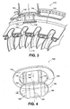
- Splash plate 124 is shown in greater detail in FIG. 4 , in which it is shown that splash plate 124 includes air deflector 128, base 140 and struts (e.g., strut 142) extending between the base and the air deflector.
- Air deflector 128 is generally planar and exhibits a major axis 136 that is perpendicular to a longitudinal axis of the engine, and a minor axis 138 that is parallel to the longitudinal axis.
- Base 140 supports air deflector 128 and includes an aperture 144.
- Air deflector 128 is spaced from the base and generally extends across a centerline 146 of aperture 144.
- the air deflector is positioned relative to the base to receive an inwardly directed, radial flow of cooling air that passes through aperture 144. The air deflector then redirects at least some of the air circumferentially, with at least some of the redirected air flowing across the exterior surfaces of the struts.
- struts 142, 143 and struts 148, 149 are used in splash plate 124.
- Each of the struts is generally rectangular in shape and extends between an edge 150 of the aperture 144 and an outer periphery 152 of air deflector 128.
- the struts establish the spacing between the base and the air deflector and, as such, the dimensions of and separation between the struts influence the flow characteristics of the cooling air entering the manifold 122 via the splash plate 124.
- various other numbers, shapes and/or configurations of struts can be used.
- cooling air flowing through conduit 120 is expelled from opening 126 so that the cooling air enters manifold 122 after passing splash plate 124.
- the flow path of the cooling air (which is primarily directed radially inwardly in this embodiment) is redirected in response to encountering the air deflector 128.
- the air deflector causes at least some of the cooling air to spread circumferentially within the manifold at a distance that is spaced from the cooling passages (e.g., passage 130) of the turbine vanes (e.g., vane 112). This enables the cooling air to spread more evenly within the manifold and into the vanes than may otherwise occur if the splash plate were not present.
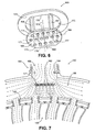
- FIG. 6 is a schematic diagram depicting another exemplary embodiment of a splash plate.
- splash plate 160 includes an air deflector 162, a base 164 and struts (e.g., strut 166) extending between the base and the air deflector.
- Air deflector 162 is generally planar and exhibits a major axis 168 that is typically oriented perpendicular to a longitudinal axis of the engine in which the splash plate is installed, and a minor axis 169 that is parallel to the longitudinal axis.
- the air deflector includes holes (e.g., hole 171) that extend between surfaces 173, 175 of the air deflector. At least some of the holes through the air deflector allow air to be directed to the vanes via line of sight flow paths in contrast to being redirected around the air deflector.
- Base 164 supports air deflector 162 and includes an aperture 170.
- Air deflector 162 is spaced from the base and generally extends across a centerline 172 of aperture 170.
- the air deflector is positioned relative to the base to receive a flow of cooling air that passes through aperture 170. The air deflector then redirects at least some of the air for distribution through an associated manifold, with at least some of the redirected air flowing across the exterior surfaces of the struts.
- struts 166, 167 and struts 176, 177 are used in splash plate 160.
- Each of the struts is generally rectangular in shape and extends from an edge 180 of the aperture 170 to an outer periphery 182 of air deflector 162.
- cooling air (depicted by arrows) flowing through a cooling air conduit 184 is expelled from an opening 186 of the conduit so that the cooling air enters a manifold 188 after passing splash plate 160.
- the flow path of the cooling air is redirected in response to encountering the air deflector 162.
- the air deflector causes at least some of the cooling air to spread circumferentially within the manifold prior to entering cooling passages (e.g., passage 190) of the turbine vanes (e.g., vane 192).
- FIG. 8 is a schematic diagram depicting another exemplary embodiment of a splash plate.
- splash plate 200 includes an air deflector 202, a base 204 and struts (e.g., strut 206) extending between the base and the air deflector.
- Air deflector 202 exhibits a major axis 208 that is typically oriented perpendicular to a longitudinal axis of the engine in which the splash plate is installed, and a minor axis 209 that is parallel to the longitudinal axis.
- Air deflector 202 also includes an intermediate portion 210 that is located between end portions 212, 214. In this embodiment, the intermediate portion exhibits a concave curve toward base 204, with the end portions exhibiting convex curves that assist in redirecting the air impinging upon the air deflector.
- Base 204 supports air deflector 202 and includes an aperture 220.
- Air deflector 202 is spaced from the base and generally extends across a centerline 222 of aperture 220.
- the air deflector is positioned relative to the base to receive a flow of cooling air that passes through aperture 220.
- the air deflector then redirects at least some of the air for distribution through an associated manifold, with at least some of the redirected air flowing across the exterior surfaces of the struts.
- the curvature exhibited by the air deflector tends to encourage air flow in a circumferential direction (i.e., toward the ends of the air deflector).
- FIG. 9 is a schematic diagram depicting another exemplary embodiment of a splash plate.
- splash plate 230 includes an air deflector 232, a base 234 and struts (e.g., strut 236) extending between the base and the air deflector.
- Air deflector 232 includes an intermediate portion 240 that is located between end portions 242, 244. In this embodiment, the intermediate portion exhibits a concave curve toward base 204, with the end portions exhibiting convex curves.
- splash plate 230 includes holes (e.g., hole 246) in the air deflector that extend from side 248 to side 249.
- Base 234 supports air deflector 232 and includes an aperture 250.
- Air deflector 232 is positioned relative to the base to receive a flow of cooling air that passes through aperture 250. The air deflector then redirects at least some of the air for distribution through an associated manifold, with at least some of the redirected air flowing across the exterior surfaces of the struts. Notably, the curvature exhibited by the air deflector tends to encourage air flow in a circumferential direction (i.e., toward the ends of the air deflector).
- FIG. 10 is a schematic diagram depicting another exemplary embodiment of a splash plate.
- splash plate 260 includes an air deflector 262, a base 264 and a pair of struts 266, 268 that extend between the base and the air deflector.
- Air deflector 262 includes an intermediate portion 270 that is located between end portions 272, 274. In this embodiment, the intermediate portion exhibits a concave curve toward base 264, with the end portions exhibiting convex curves.
- Base 264 supports air deflector 262 and includes an aperture 270.
- Air deflector 262 is positioned relative to the base by struts 266, 268 to receive a flow of cooling air that passes through aperture 270. The air deflector then redirects at least some of the air for distribution through an associated manifold, with at least some of the redirected air flowing across the exterior surfaces of the struts.
- at least the trailing strut 266 (which is located downstream of strut 268 relative to the core flow of the engine in which the splash plate is mounted) includes holes (e.g., hole 272) through which redirected cooling air also can flow. Such holes can encourage downstream flow of the cooling air within the manifold. In other embodiments, neither, either or both of the struts can incorporate holes.
Landscapes
- Engineering & Computer Science (AREA)
- Mechanical Engineering (AREA)
- General Engineering & Computer Science (AREA)
- Chemical & Material Sciences (AREA)
- Combustion & Propulsion (AREA)
- Physics & Mathematics (AREA)
- Fluid Mechanics (AREA)
- Turbine Rotor Nozzle Sealing (AREA)
Applications Claiming Priority (1)
| Application Number | Priority Date | Filing Date | Title |
|---|---|---|---|
| US12/045,781 US8100633B2 (en) | 2008-03-11 | 2008-03-11 | Cooling air manifold splash plates and gas turbines engine systems involving such splash plates |
Publications (3)
| Publication Number | Publication Date |
|---|---|
| EP2101041A2 true EP2101041A2 (fr) | 2009-09-16 |
| EP2101041A3 EP2101041A3 (fr) | 2012-10-24 |
| EP2101041B1 EP2101041B1 (fr) | 2016-11-16 |
Family
ID=40688412
Family Applications (1)
| Application Number | Title | Priority Date | Filing Date |
|---|---|---|---|
| EP09250679.9A Active EP2101041B1 (fr) | 2008-03-11 | 2009-03-11 | Plaque de pulvérisation pour un distributeur d'air de refroidissement d'un moteur à turbine à gaz |
Country Status (2)
| Country | Link |
|---|---|
| US (1) | US8100633B2 (fr) |
| EP (1) | EP2101041B1 (fr) |
Cited By (3)
| Publication number | Priority date | Publication date | Assignee | Title |
|---|---|---|---|---|
| US9194246B2 (en) | 2011-09-23 | 2015-11-24 | General Electric Company | Steam turbine LP casing cylindrical struts between stages |
| EP3101228A1 (fr) * | 2015-05-08 | 2016-12-07 | United Technologies Corporation | Déflecteur de division d'écoulement |
| US9920643B2 (en) | 2014-05-14 | 2018-03-20 | Rolls-Royce Plc | Distributor device for cooling air within an engine |
Families Citing this family (17)
| Publication number | Priority date | Publication date | Assignee | Title |
|---|---|---|---|---|
| US8529195B2 (en) * | 2010-10-12 | 2013-09-10 | General Electric Company | Inducer for gas turbine system |
| US9403208B2 (en) | 2010-12-30 | 2016-08-02 | United Technologies Corporation | Method and casting core for forming a landing for welding a baffle inserted in an airfoil |
| US9677472B2 (en) | 2012-10-08 | 2017-06-13 | United Technologies Corporation | Bleed air slot |
| US9739171B2 (en) | 2012-11-16 | 2017-08-22 | United Technologies Corporation | Turbine engine cooling system with an open loop circuit |
| US9927123B2 (en) * | 2013-10-24 | 2018-03-27 | United Technologies Corporation | Fluid transport system having divided transport tube |
| US9803501B2 (en) * | 2014-02-14 | 2017-10-31 | United Technologies Corporation | Engine mid-turbine frame distributive coolant flow |
| US10309308B2 (en) * | 2015-01-16 | 2019-06-04 | United Technologies Corporation | Cooling passages for a mid-turbine frame |
| DE102016124806A1 (de) * | 2016-12-19 | 2018-06-21 | Rolls-Royce Deutschland Ltd & Co Kg | Turbinen-Laufschaufelanordnung für eine Gasturbine und Verfahren zum Bereitstellen von Dichtluft in einer Turbinen-Laufschaufelanordnung |
| US10718267B2 (en) * | 2017-12-14 | 2020-07-21 | Rolls-Royce Corporation | Turbine engine cooling with substantially uniform cooling air flow distribution |
| US10738637B2 (en) | 2017-12-22 | 2020-08-11 | Raytheon Technologies Corporation | Airflow deflector and assembly |
| US10982546B2 (en) * | 2018-09-19 | 2021-04-20 | General Electric Company | Flow-diverting systems for gas turbine air separator |
| FR3089545B1 (fr) * | 2018-12-07 | 2021-01-29 | Safran Aircraft Engines | Dispositif de refroidissement d’un carter de turbine pour une turbomachine |
| US11421597B2 (en) * | 2019-10-18 | 2022-08-23 | Pratt & Whitney Canada Corp. | Tangential on-board injector (TOBI) assembly |
| US11698005B2 (en) | 2020-02-07 | 2023-07-11 | Raytheon Technologies Corporation | Flow diverter for mid-turbine frame cooling air delivery |
| CN114198153B (zh) * | 2020-09-17 | 2024-05-03 | 中国航发商用航空发动机有限责任公司 | 涡轮叶片冷却系统及航空发动机 |
| US20220316352A1 (en) * | 2021-03-31 | 2022-10-06 | Raytheon Technologies Corporation | Flow diverter for mid-turbine frame cooling air delivery |
| JPWO2024053326A1 (fr) * | 2022-09-05 | 2024-03-14 |
Citations (5)
| Publication number | Priority date | Publication date | Assignee | Title |
|---|---|---|---|---|
| US3864056A (en) | 1973-07-27 | 1975-02-04 | Westinghouse Electric Corp | Cooled turbine blade ring assembly |
| GB2019503A (en) | 1978-04-20 | 1979-10-31 | Gen Electric | Turbine cooling system |
| US5234161A (en) | 1992-05-08 | 1993-08-10 | Baltimore Aircoil Company | Counterflow spray nozzle |
| US6929445B2 (en) | 2003-10-22 | 2005-08-16 | General Electric Company | Split flow turbine nozzle |
| US7109479B2 (en) | 2001-04-16 | 2006-09-19 | The Rockefeller University | Method and system for mass spectroscopy |
Family Cites Families (21)
| Publication number | Priority date | Publication date | Assignee | Title |
|---|---|---|---|---|
| US266142A (en) * | 1882-10-17 | Island | ||
| US3529941A (en) * | 1967-04-24 | 1970-09-22 | Monsanto Co | Liquid deflection apparatus |
| GB1305887A (fr) * | 1971-07-01 | 1973-02-07 | ||
| IT1068487B (it) * | 1975-07-24 | 1985-03-21 | Balcke Duerr Ag | Dispositivo per la spruzzatura di acqua in impianti di riraffredamento dell acqua |
| GB1575410A (en) * | 1976-09-04 | 1980-09-24 | Rolls Royce | Combustion apparatus for use in gas turbine engines |
| US5165847A (en) * | 1991-05-20 | 1992-11-24 | General Electric Company | Tapered enlargement metering inlet channel for a shroud cooling assembly of gas turbine engines |
| US5239816A (en) * | 1992-03-16 | 1993-08-31 | General Electric Company | Steam deflector assembly for a steam injected gas turbine engine |
| US5538393A (en) | 1995-01-31 | 1996-07-23 | United Technologies Corporation | Turbine shroud segment with serpentine cooling channels having a bend passage |
| FR2766517B1 (fr) * | 1997-07-24 | 1999-09-03 | Snecma | Dispositif de ventilation d'un anneau de turbomachine |
| US6241467B1 (en) | 1999-08-02 | 2001-06-05 | United Technologies Corporation | Stator vane for a rotary machine |
| US6325595B1 (en) | 2000-03-24 | 2001-12-04 | General Electric Company | High recovery multi-use bleed |
| US6585482B1 (en) | 2000-06-20 | 2003-07-01 | General Electric Co. | Methods and apparatus for delivering cooling air within gas turbines |
| US6550254B2 (en) | 2001-08-17 | 2003-04-22 | General Electric Company | Gas turbine engine bleed scoops |
| US6735956B2 (en) | 2001-10-26 | 2004-05-18 | Pratt & Whitney Canada Corp. | High pressure turbine blade cooling scoop |
| US6761529B2 (en) | 2002-07-25 | 2004-07-13 | Mitshubishi Heavy Industries, Ltd. | Cooling structure of stationary blade, and gas turbine |
| US6783324B2 (en) | 2002-08-15 | 2004-08-31 | General Electric Company | Compressor bleed case |
| US7033138B2 (en) * | 2002-09-06 | 2006-04-25 | Mitsubishi Heavy Industries, Ltd. | Ring segment of gas turbine |
| US7108479B2 (en) * | 2003-06-19 | 2006-09-19 | General Electric Company | Methods and apparatus for supplying cooling fluid to turbine nozzles |
| US7090461B2 (en) | 2003-10-30 | 2006-08-15 | Siemens Westinghouse Power Corporation | Gas turbine vane with integral cooling flow control system |
| US7192245B2 (en) | 2004-12-03 | 2007-03-20 | Pratt & Whitney Canada Corp. | Rotor assembly with cooling air deflectors and method |
| US7670108B2 (en) * | 2006-11-21 | 2010-03-02 | Siemens Energy, Inc. | Air seal unit adapted to be positioned adjacent blade structure in a gas turbine |
-
2008
- 2008-03-11 US US12/045,781 patent/US8100633B2/en active Active
-
2009
- 2009-03-11 EP EP09250679.9A patent/EP2101041B1/fr active Active
Patent Citations (5)
| Publication number | Priority date | Publication date | Assignee | Title |
|---|---|---|---|---|
| US3864056A (en) | 1973-07-27 | 1975-02-04 | Westinghouse Electric Corp | Cooled turbine blade ring assembly |
| GB2019503A (en) | 1978-04-20 | 1979-10-31 | Gen Electric | Turbine cooling system |
| US5234161A (en) | 1992-05-08 | 1993-08-10 | Baltimore Aircoil Company | Counterflow spray nozzle |
| US7109479B2 (en) | 2001-04-16 | 2006-09-19 | The Rockefeller University | Method and system for mass spectroscopy |
| US6929445B2 (en) | 2003-10-22 | 2005-08-16 | General Electric Company | Split flow turbine nozzle |
Cited By (4)
| Publication number | Priority date | Publication date | Assignee | Title |
|---|---|---|---|---|
| US9194246B2 (en) | 2011-09-23 | 2015-11-24 | General Electric Company | Steam turbine LP casing cylindrical struts between stages |
| US9920643B2 (en) | 2014-05-14 | 2018-03-20 | Rolls-Royce Plc | Distributor device for cooling air within an engine |
| EP3101228A1 (fr) * | 2015-05-08 | 2016-12-07 | United Technologies Corporation | Déflecteur de division d'écoulement |
| US9926789B2 (en) | 2015-05-08 | 2018-03-27 | United Technologies Corporation | Flow splitting baffle |
Also Published As
| Publication number | Publication date |
|---|---|
| EP2101041A3 (fr) | 2012-10-24 |
| EP2101041B1 (fr) | 2016-11-16 |
| US8100633B2 (en) | 2012-01-24 |
| US20090232637A1 (en) | 2009-09-17 |
Similar Documents
| Publication | Publication Date | Title |
|---|---|---|
| US8100633B2 (en) | Cooling air manifold splash plates and gas turbines engine systems involving such splash plates | |
| US10125684B2 (en) | Surface cooler for aero engine | |
| US9810081B2 (en) | Cooled conduit for conveying combustion gases | |
| US6179557B1 (en) | Turbine cooling | |
| US9046269B2 (en) | Impingement cooling device | |
| EP1608846B1 (fr) | Procede de production d'un composant stator | |
| US10344606B2 (en) | Stator vane arrangement for a turbine engine | |
| US20130028718A1 (en) | Strut, a gas turbine engine frame comprising the strut and a gas turbine engine comprising the frame | |
| EP2944768B1 (fr) | Dispositif distributeur pour refroidir l'air à l'intérieur d'un moteur | |
| US9556746B2 (en) | Integrated strut and turbine vane nozzle arrangement | |
| US8979484B2 (en) | Casing for an aircraft turbofan bypass engine | |
| CN108291721B (zh) | 过渡构造 | |
| JP2009062976A (ja) | ディフューザを有するターボ機械 | |
| CN101634313B (zh) | 带槽的压缩机扩散器及相关方法 | |
| US20160123186A1 (en) | Shroud assembly for a turbine engine | |
| US11391176B2 (en) | Method and apparatus for supplying cooling air to a turbine | |
| US8246297B2 (en) | Shroud segment cooling configuration | |
| CN1978867A (zh) | 用于涡轮转子平衡的方法和系统 | |
| US20160258302A1 (en) | Airfoil and method for managing pressure at tip of airfoil | |
| US10724391B2 (en) | Engine component with flow enhancer | |
| US9039370B2 (en) | Turbine nozzle | |
| WO2020086069A1 (fr) | Système de conduit de transition comprenant des chemises thermiquement isolantes non métalliques supportées par des structures de coque métalliques divisibles pour distribuer des gaz à température chaude dans un moteur à turbine à combustion | |
| EP3279433A1 (fr) | Composant de turbomachine avec guides d'écoulement pour film, film de trous de refroidissement dans un système de refroidissement |
Legal Events
| Date | Code | Title | Description |
|---|---|---|---|
| PUAI | Public reference made under article 153(3) epc to a published international application that has entered the european phase |
Free format text: ORIGINAL CODE: 0009012 |
|
| AK | Designated contracting states |
Kind code of ref document: A2 Designated state(s): AT BE BG CH CY CZ DE DK EE ES FI FR GB GR HR HU IE IS IT LI LT LU LV MC MK MT NL NO PL PT RO SE SI SK TR |
|
| AX | Request for extension of the european patent |
Extension state: AL BA RS |
|
| PUAL | Search report despatched |
Free format text: ORIGINAL CODE: 0009013 |
|
| AK | Designated contracting states |
Kind code of ref document: A3 Designated state(s): AT BE BG CH CY CZ DE DK EE ES FI FR GB GR HR HU IE IS IT LI LT LU LV MC MK MT NL NO PL PT RO SE SI SK TR |
|
| AX | Request for extension of the european patent |
Extension state: AL BA RS |
|
| RIC1 | Information provided on ipc code assigned before grant |
Ipc: F01D 9/06 20060101AFI20120919BHEP Ipc: F02C 7/18 20060101ALI20120919BHEP |
|
| 17P | Request for examination filed |
Effective date: 20130424 |
|
| AKX | Designation fees paid |
Designated state(s): DE GB |
|
| 17Q | First examination report despatched |
Effective date: 20150723 |
|
| GRAP | Despatch of communication of intention to grant a patent |
Free format text: ORIGINAL CODE: EPIDOSNIGR1 |
|
| INTG | Intention to grant announced |
Effective date: 20160711 |
|
| GRAS | Grant fee paid |
Free format text: ORIGINAL CODE: EPIDOSNIGR3 |
|
| GRAA | (expected) grant |
Free format text: ORIGINAL CODE: 0009210 |
|
| RAP1 | Party data changed (applicant data changed or rights of an application transferred) |
Owner name: UNITED TECHNOLOGIES CORPORATION |
|
| AK | Designated contracting states |
Kind code of ref document: B1 Designated state(s): DE GB |
|
| REG | Reference to a national code |
Ref country code: GB Ref legal event code: FG4D |
|
| REG | Reference to a national code |
Ref country code: DE Ref legal event code: R096 Ref document number: 602009042407 Country of ref document: DE |
|
| REG | Reference to a national code |
Ref country code: DE Ref legal event code: R082 Ref document number: 602009042407 Country of ref document: DE Representative=s name: SCHMITT-NILSON SCHRAUD WAIBEL WOHLFROM PATENTA, DE |
|
| REG | Reference to a national code |
Ref country code: DE Ref legal event code: R097 Ref document number: 602009042407 Country of ref document: DE |
|
| PLBE | No opposition filed within time limit |
Free format text: ORIGINAL CODE: 0009261 |
|
| STAA | Information on the status of an ep patent application or granted ep patent |
Free format text: STATUS: NO OPPOSITION FILED WITHIN TIME LIMIT |
|
| 26N | No opposition filed |
Effective date: 20170817 |
|
| REG | Reference to a national code |
Ref country code: DE Ref legal event code: R081 Ref document number: 602009042407 Country of ref document: DE Owner name: RAYTHEON TECHNOLOGIES CORPORATION (N.D.GES.D.S, US Free format text: FORMER OWNER: UNITED TECHNOLOGIES CORPORATION, FARMINGTON, CONN., US Ref country code: DE Ref legal event code: R081 Ref document number: 602009042407 Country of ref document: DE Owner name: RTX CORPORATION (N.D.GES.D. STAATES DELAWARE),, US Free format text: FORMER OWNER: UNITED TECHNOLOGIES CORPORATION, FARMINGTON, CONN., US |
|
| P01 | Opt-out of the competence of the unified patent court (upc) registered |
Effective date: 20230519 |
|
| REG | Reference to a national code |
Ref country code: DE Ref legal event code: R081 Ref document number: 602009042407 Country of ref document: DE Owner name: RTX CORPORATION (N.D.GES.D. STAATES DELAWARE),, US Free format text: FORMER OWNER: RAYTHEON TECHNOLOGIES CORPORATION (N.D.GES.D.STAATES DELAWARE), ARLINGTON, VA, US |
|
| PGFP | Annual fee paid to national office [announced via postgrant information from national office to epo] |
Ref country code: GB Payment date: 20260219 Year of fee payment: 18 |
|
| PGFP | Annual fee paid to national office [announced via postgrant information from national office to epo] |
Ref country code: DE Payment date: 20260219 Year of fee payment: 18 |