EP2101107A2 - Appareil de phare de véhicule - Google Patents
Appareil de phare de véhicule Download PDFInfo
- Publication number
- EP2101107A2 EP2101107A2 EP09003562A EP09003562A EP2101107A2 EP 2101107 A2 EP2101107 A2 EP 2101107A2 EP 09003562 A EP09003562 A EP 09003562A EP 09003562 A EP09003562 A EP 09003562A EP 2101107 A2 EP2101107 A2 EP 2101107A2
- Authority
- EP
- European Patent Office
- Prior art keywords
- light emitting
- partial region
- lamp unit
- light
- additional
- Prior art date
- Legal status (The legal status is an assumption and is not a legal conclusion. Google has not performed a legal analysis and makes no representation as to the accuracy of the status listed.)
- Granted
Links
- 230000003287 optical effect Effects 0.000 claims description 72
- 101150072055 PAL1 gene Proteins 0.000 description 15
- 101100192827 Saccharomyces cerevisiae (strain ATCC 204508 / S288c) PXA1 gene Proteins 0.000 description 15
- 101150077062 pal gene Proteins 0.000 description 15
- 238000010586 diagram Methods 0.000 description 14
- 101001098529 Homo sapiens Proteinase-activated receptor 1 Proteins 0.000 description 13
- 101000713169 Homo sapiens Solute carrier family 52, riboflavin transporter, member 2 Proteins 0.000 description 13
- 102100037136 Proteinase-activated receptor 1 Human genes 0.000 description 13
- 101150009729 Pal2 gene Proteins 0.000 description 11
- 101150051586 RIM21 gene Proteins 0.000 description 11
- 101100462598 Arabidopsis thaliana PAL4 gene Proteins 0.000 description 9
- 101100489581 Caenorhabditis elegans par-5 gene Proteins 0.000 description 9
- 101150081344 PAL3 gene Proteins 0.000 description 9
- 101150080283 RIM8 gene Proteins 0.000 description 9
- 101000603877 Homo sapiens Nuclear receptor subfamily 1 group I member 2 Proteins 0.000 description 8
- 101001098560 Homo sapiens Proteinase-activated receptor 2 Proteins 0.000 description 8
- 101000713170 Homo sapiens Solute carrier family 52, riboflavin transporter, member 1 Proteins 0.000 description 8
- 102100037132 Proteinase-activated receptor 2 Human genes 0.000 description 8
- 230000004313 glare Effects 0.000 description 7
- 101001135199 Homo sapiens Partitioning defective 3 homolog Proteins 0.000 description 6
- 101001098557 Homo sapiens Proteinase-activated receptor 3 Proteins 0.000 description 6
- 102100037133 Proteinase-activated receptor 3 Human genes 0.000 description 6
- 230000003247 decreasing effect Effects 0.000 description 4
- 230000004044 response Effects 0.000 description 4
- 239000010409 thin film Substances 0.000 description 4
- 101000613565 Homo sapiens PRKC apoptosis WT1 regulator protein Proteins 0.000 description 3
- 101001113471 Homo sapiens Proteinase-activated receptor 4 Proteins 0.000 description 3
- 102100023710 Proteinase-activated receptor 4 Human genes 0.000 description 3
- 101000983338 Solanum commersonii Osmotin-like protein OSML15 Proteins 0.000 description 2
- 229910052782 aluminium Inorganic materials 0.000 description 2
- XAGFODPZIPBFFR-UHFFFAOYSA-N aluminium Chemical compound [Al] XAGFODPZIPBFFR-UHFFFAOYSA-N 0.000 description 2
- 230000000052 comparative effect Effects 0.000 description 2
- 238000001514 detection method Methods 0.000 description 2
- 230000006870 function Effects 0.000 description 2
- 230000001678 irradiating effect Effects 0.000 description 2
- 239000003550 marker Substances 0.000 description 2
- 229910052751 metal Inorganic materials 0.000 description 2
- 239000002184 metal Substances 0.000 description 2
- 230000004297 night vision Effects 0.000 description 2
- 230000009467 reduction Effects 0.000 description 2
- 239000011347 resin Substances 0.000 description 2
- 229920005989 resin Polymers 0.000 description 2
- 101000701286 Pseudomonas aeruginosa (strain ATCC 15692 / DSM 22644 / CIP 104116 / JCM 14847 / LMG 12228 / 1C / PRS 101 / PAO1) Alkanesulfonate monooxygenase Proteins 0.000 description 1
- 101000983349 Solanum commersonii Osmotin-like protein OSML13 Proteins 0.000 description 1
- 230000002238 attenuated effect Effects 0.000 description 1
- 230000005540 biological transmission Effects 0.000 description 1
- 230000000295 complement effect Effects 0.000 description 1
- 229910052736 halogen Inorganic materials 0.000 description 1
- 150000002367 halogens Chemical class 0.000 description 1
- 238000003384 imaging method Methods 0.000 description 1
- 239000011159 matrix material Substances 0.000 description 1
- 229910001507 metal halide Inorganic materials 0.000 description 1
- 150000005309 metal halides Chemical class 0.000 description 1
- 229910044991 metal oxide Inorganic materials 0.000 description 1
- 150000004706 metal oxides Chemical class 0.000 description 1
- 238000000034 method Methods 0.000 description 1
- 238000011112 process operation Methods 0.000 description 1
- 239000004065 semiconductor Substances 0.000 description 1
- 230000007704 transition Effects 0.000 description 1
Images





Classifications
-
- F—MECHANICAL ENGINEERING; LIGHTING; HEATING; WEAPONS; BLASTING
- F21—LIGHTING
- F21S—NON-PORTABLE LIGHTING DEVICES; SYSTEMS THEREOF; VEHICLE LIGHTING DEVICES SPECIALLY ADAPTED FOR VEHICLE EXTERIORS
- F21S41/00—Illuminating devices specially adapted for vehicle exteriors, e.g. headlamps
- F21S41/10—Illuminating devices specially adapted for vehicle exteriors, e.g. headlamps characterised by the light source
- F21S41/14—Illuminating devices specially adapted for vehicle exteriors, e.g. headlamps characterised by the light source characterised by the type of light source
- F21S41/141—Light emitting diodes [LED]
- F21S41/155—Surface emitters, e.g. organic light emitting diodes [OLED]
-
- B—PERFORMING OPERATIONS; TRANSPORTING
- B60—VEHICLES IN GENERAL
- B60Q—ARRANGEMENT OF SIGNALLING OR LIGHTING DEVICES, THE MOUNTING OR SUPPORTING THEREOF OR CIRCUITS THEREFOR, FOR VEHICLES IN GENERAL
- B60Q1/00—Arrangement of optical signalling or lighting devices, the mounting or supporting thereof or circuits therefor
- B60Q1/02—Arrangement of optical signalling or lighting devices, the mounting or supporting thereof or circuits therefor the devices being primarily intended to illuminate the way ahead or to illuminate other areas of way or environments
- B60Q1/04—Arrangement of optical signalling or lighting devices, the mounting or supporting thereof or circuits therefor the devices being primarily intended to illuminate the way ahead or to illuminate other areas of way or environments the devices being headlights
- B60Q1/06—Arrangement of optical signalling or lighting devices, the mounting or supporting thereof or circuits therefor the devices being primarily intended to illuminate the way ahead or to illuminate other areas of way or environments the devices being headlights adjustable, e.g. remotely-controlled from inside vehicle
- B60Q1/08—Arrangement of optical signalling or lighting devices, the mounting or supporting thereof or circuits therefor the devices being primarily intended to illuminate the way ahead or to illuminate other areas of way or environments the devices being headlights adjustable, e.g. remotely-controlled from inside vehicle automatically
- B60Q1/085—Arrangement of optical signalling or lighting devices, the mounting or supporting thereof or circuits therefor the devices being primarily intended to illuminate the way ahead or to illuminate other areas of way or environments the devices being headlights adjustable, e.g. remotely-controlled from inside vehicle automatically due to special conditions, e.g. adverse weather, type of road, badly illuminated road signs or potential dangers
-
- F—MECHANICAL ENGINEERING; LIGHTING; HEATING; WEAPONS; BLASTING
- F21—LIGHTING
- F21S—NON-PORTABLE LIGHTING DEVICES; SYSTEMS THEREOF; VEHICLE LIGHTING DEVICES SPECIALLY ADAPTED FOR VEHICLE EXTERIORS
- F21S41/00—Illuminating devices specially adapted for vehicle exteriors, e.g. headlamps
- F21S41/10—Illuminating devices specially adapted for vehicle exteriors, e.g. headlamps characterised by the light source
- F21S41/14—Illuminating devices specially adapted for vehicle exteriors, e.g. headlamps characterised by the light source characterised by the type of light source
- F21S41/141—Light emitting diodes [LED]
- F21S41/143—Light emitting diodes [LED] the main emission direction of the LED being parallel to the optical axis of the illuminating device
-
- F—MECHANICAL ENGINEERING; LIGHTING; HEATING; WEAPONS; BLASTING
- F21—LIGHTING
- F21S—NON-PORTABLE LIGHTING DEVICES; SYSTEMS THEREOF; VEHICLE LIGHTING DEVICES SPECIALLY ADAPTED FOR VEHICLE EXTERIORS
- F21S41/00—Illuminating devices specially adapted for vehicle exteriors, e.g. headlamps
- F21S41/10—Illuminating devices specially adapted for vehicle exteriors, e.g. headlamps characterised by the light source
- F21S41/14—Illuminating devices specially adapted for vehicle exteriors, e.g. headlamps characterised by the light source characterised by the type of light source
- F21S41/141—Light emitting diodes [LED]
- F21S41/151—Light emitting diodes [LED] arranged in one or more lines
-
- F—MECHANICAL ENGINEERING; LIGHTING; HEATING; WEAPONS; BLASTING
- F21—LIGHTING
- F21S—NON-PORTABLE LIGHTING DEVICES; SYSTEMS THEREOF; VEHICLE LIGHTING DEVICES SPECIALLY ADAPTED FOR VEHICLE EXTERIORS
- F21S41/00—Illuminating devices specially adapted for vehicle exteriors, e.g. headlamps
- F21S41/60—Illuminating devices specially adapted for vehicle exteriors, e.g. headlamps characterised by a variable light distribution
- F21S41/65—Illuminating devices specially adapted for vehicle exteriors, e.g. headlamps characterised by a variable light distribution by acting on light sources
- F21S41/663—Illuminating devices specially adapted for vehicle exteriors, e.g. headlamps characterised by a variable light distribution by acting on light sources by switching light sources
-
- F—MECHANICAL ENGINEERING; LIGHTING; HEATING; WEAPONS; BLASTING
- F21—LIGHTING
- F21S—NON-PORTABLE LIGHTING DEVICES; SYSTEMS THEREOF; VEHICLE LIGHTING DEVICES SPECIALLY ADAPTED FOR VEHICLE EXTERIORS
- F21S43/00—Signalling devices specially adapted for vehicle exteriors, e.g. brake lamps, direction indicator lights or reversing lights
- F21S43/50—Signalling devices specially adapted for vehicle exteriors, e.g. brake lamps, direction indicator lights or reversing lights characterised by aesthetic components not otherwise provided for, e.g. decorative trim, partition walls or covers
-
- B—PERFORMING OPERATIONS; TRANSPORTING
- B60—VEHICLES IN GENERAL
- B60Q—ARRANGEMENT OF SIGNALLING OR LIGHTING DEVICES, THE MOUNTING OR SUPPORTING THEREOF OR CIRCUITS THEREFOR, FOR VEHICLES IN GENERAL
- B60Q2300/00—Indexing codes for automatically adjustable headlamps or automatically dimmable headlamps
- B60Q2300/05—Special features for controlling or switching of the light beam
- B60Q2300/054—Variable non-standard intensity, i.e. emission of various beam intensities different from standard intensities, e.g. continuous or stepped transitions of intensity
-
- B—PERFORMING OPERATIONS; TRANSPORTING
- B60—VEHICLES IN GENERAL
- B60Q—ARRANGEMENT OF SIGNALLING OR LIGHTING DEVICES, THE MOUNTING OR SUPPORTING THEREOF OR CIRCUITS THEREFOR, FOR VEHICLES IN GENERAL
- B60Q2300/00—Indexing codes for automatically adjustable headlamps or automatically dimmable headlamps
- B60Q2300/05—Special features for controlling or switching of the light beam
- B60Q2300/056—Special anti-blinding beams, e.g. a standard beam is chopped or moved in order not to blind
-
- B—PERFORMING OPERATIONS; TRANSPORTING
- B60—VEHICLES IN GENERAL
- B60Q—ARRANGEMENT OF SIGNALLING OR LIGHTING DEVICES, THE MOUNTING OR SUPPORTING THEREOF OR CIRCUITS THEREFOR, FOR VEHICLES IN GENERAL
- B60Q2300/00—Indexing codes for automatically adjustable headlamps or automatically dimmable headlamps
- B60Q2300/40—Indexing codes relating to other road users or special conditions
- B60Q2300/41—Indexing codes relating to other road users or special conditions preceding vehicle
-
- B—PERFORMING OPERATIONS; TRANSPORTING
- B60—VEHICLES IN GENERAL
- B60Q—ARRANGEMENT OF SIGNALLING OR LIGHTING DEVICES, THE MOUNTING OR SUPPORTING THEREOF OR CIRCUITS THEREFOR, FOR VEHICLES IN GENERAL
- B60Q2300/00—Indexing codes for automatically adjustable headlamps or automatically dimmable headlamps
- B60Q2300/40—Indexing codes relating to other road users or special conditions
- B60Q2300/42—Indexing codes relating to other road users or special conditions oncoming vehicle
-
- B—PERFORMING OPERATIONS; TRANSPORTING
- B60—VEHICLES IN GENERAL
- B60Q—ARRANGEMENT OF SIGNALLING OR LIGHTING DEVICES, THE MOUNTING OR SUPPORTING THEREOF OR CIRCUITS THEREFOR, FOR VEHICLES IN GENERAL
- B60Q2300/00—Indexing codes for automatically adjustable headlamps or automatically dimmable headlamps
- B60Q2300/40—Indexing codes relating to other road users or special conditions
- B60Q2300/45—Special conditions, e.g. pedestrians, road signs or potential dangers
-
- F—MECHANICAL ENGINEERING; LIGHTING; HEATING; WEAPONS; BLASTING
- F21—LIGHTING
- F21S—NON-PORTABLE LIGHTING DEVICES; SYSTEMS THEREOF; VEHICLE LIGHTING DEVICES SPECIALLY ADAPTED FOR VEHICLE EXTERIORS
- F21S41/00—Illuminating devices specially adapted for vehicle exteriors, e.g. headlamps
- F21S41/20—Illuminating devices specially adapted for vehicle exteriors, e.g. headlamps characterised by refractors, transparent cover plates, light guides or filters
- F21S41/24—Light guides
-
- F—MECHANICAL ENGINEERING; LIGHTING; HEATING; WEAPONS; BLASTING
- F21—LIGHTING
- F21Y—INDEXING SCHEME ASSOCIATED WITH SUBCLASSES F21K, F21L, F21S and F21V, RELATING TO THE FORM OR THE KIND OF THE LIGHT SOURCES OR OF THE COLOUR OF THE LIGHT EMITTED
- F21Y2115/00—Light-generating elements of semiconductor light sources
- F21Y2115/10—Light-emitting diodes [LED]
Definitions
- Apparatuses consistent with the present invention relate to vehicle headlamps.
- headlamps When vehicles are driven at nighttime, headlamps are normally turned on in a so-called “low beam” mode so as to illuminate surfaces of roads, and if necessary, the headlamps are turned on in a so-called “high beam” mode so as to better view regions in front of the vehicles.
- low beam low beam
- high beam high beam
- glare may be generated for drivers of preceding vehicles (i.e., vehicles traveling in front of the vehicle and in the same direction as the vehicle) and also pedestrians who are present in areas in front of the vehicles.
- vehicle headlamps have been proposed by which, for example, positions of persons in front of the vehicle are determined, and then, masks having dimensions and positions corresponding to the determined persons are formed on image forming devices so as to form shadows projected around the persons (see, e.g., JP 2004-231178 A ).
- vehicle headlamp apparatuses have been proposed by which, for example, a detection is made whether or not a preceding vehicle is present; light of the vehicle headlamps is controlled in response to a detection result such that the light directed to one direction is reduced; and accordingly, the reduced light is irradiated to the other direction (see, e.g., JP 4-081337 A ).
- vehicle-purpose night vision systems have been proposed (see, e.g., JP 2006-188224 A ). That is, in the vehicle-purpose night vision systems, for example, an object is detected, and then light of at least one pixel among a plurality of pixels within an optical attenuation matrix is attenuated in response to the detected result.
- the drive of the vehicle may not be able to adequately see the pavement marker, delineator, or pedestrian, creating a dangerous situation.
- Exemplary embodiments of the present invention address the above disadvantages and other disadvantages not described above.
- the present invention is not required to overcome the disadvantages described above, and thus, an exemplary embodiment of the present invention may not overcome any of the problems described above.
- Illustrative aspects of the present invention provide a vehicle headlamp apparatus capable of suppressing glare given to a preceding vehicle and/or a pedestrian, while the vehicle headlamp apparatus is capable of suppressing an occurrence of such a forward region which can cause difficulty for a vehicle driver of the vehicle.
- a vehicle headlamp apparatus includes a low beam lamp unit which forms a low beam distribution pattern, a first additional lamp unit which forms a first additional light distributing pattern at least partially above a cutoff line of the low beam distributing pattern, a second additional lamp unit which forms a second additional light distributing pattern overlapping with the first additional light distributing pattern, and a controller.
- the first additional light distributing pattern includes at least one first partial region, and the first additional lamp unit is configured such that a luminous intensity of a light to be irradiated toward the first partial region is adjustable.
- the second additional light distributing pattern includes at least one second partial region which partially overlaps with the first partial region, and the second additional lamp unit is configured such that a luminous intensity of a light to be irradiated toward the second partial region is adjustable.
- the controller controls the first additional lamp unit to adjust the luminous intensity of the light to be irradiated toward the first partial region and controls the second additional lamp unit to adjust the luminous intensity of the light to be irradiated toward the second partial region.
- Fig. 1 is a schematic diagram of a vehicle on which a headlamp apparatus according to an exemplary embodiment of the present invention is mounted;
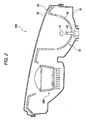
- Fig. 2 is a horizontal sectional view of a right headlamp according to a first exemplary embodiment of the present invention;
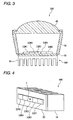
- Fig. 3 is a horizontal sectional view of a second right lamp unit of the right headlamp of Fig. 2 ;
- Fig. 4 is a perspective view of a right light emitting unit of the second right lamp unit of Fig. 3 ;
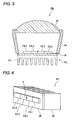
- Fig. 5 is a horizontal sectional view of a second left lamp unit according to the first exemplary embodiment of the present invention;
- Fig. 6 is a perspective view of a left light emitting unit of the second left lamp unit of Fig. 5 ;
- Fig. 1 is a schematic diagram of a vehicle on which a headlamp apparatus according to an exemplary embodiment of the present invention is mounted;
- Fig. 2 is a horizontal sectional view of a right headlamp according to a first exemplary
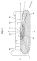
- FIG. 7 is a diagram illustrating a light distributing pattern formed on a virtual vertical screen located in front of the vehicle by forwardly irradiating light from right and left headlamps;
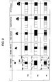
- Fig. 8A is a diagram illustrating a right additional light distributing pattern PAR;
- Fig. 8B is a diagram illustrating a left additional light distributing pattern PAL;
- Fig. 8C is a diagram illustrating an additional light distributing pattern PA which is a combination of the right additional light distributing pattern PAR and the left additional light distributing pattern PAL;
- Fig. 9 is a diagram illustrating a relationship of various positions of an oncoming vehicle with respect to the right additional light distributing pattern PAR, the left additional light distributing pattern PAL, and the additional light distributing pattern PA when an intermediate beam mode is selected;
- Fig. 8A is a diagram illustrating a right additional light distributing pattern PAR
- Fig. 8B is a diagram illustrating a left additional light distributing pattern PAL
- Fig. 8C is a diagram
- FIG. 10 is a diagram illustrating a relationship between the additional light distributing pattern PA and the respective positions of the oncoming vehicle when the intermediate beam mode is selected in a comparative configuration in which each of the right additional light distributing pattern PAR and the left additional light distributing pattern PAL is divided into the same shapes, such that right partial regions and left partial regions share the same partial regions PA11 to PA15;
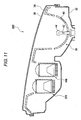
- Fig. 11 is a horizontal sectional view of a right headlamp according to a second exemplary embodiment of the present invention;
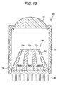
- Fig. 12 is a horizontal sectional view of a second right lamp unit of the right headlamp of Fig. 11 ;
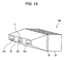
- Fig. 13 is a perspective view of a right light emitting unit of the second right lamp unit of Fig. 12 ;
- Fig. 11 is a horizontal sectional view of a right headlamp according to a second exemplary embodiment of the present invention
- Fig. 12 is a horizontal sectional view of a second right lamp unit of the right headlamp of Fig. 11
- Fig. 13
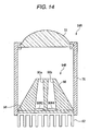
- Fig. 14 is a horizontal sectional view of a third right lamp unit of the right headlamp of Fig. 11 ;
- Fig. 15 is a perspective view of a right light emitting unit of the third right lamp unit of Fig. 14 ;
- Fig. 16 is a horizontal sectional view of a second left lamp unit according to the second exemplary embodiment of the present invention;
- Fig. 17 is a perspective view of a left light emitting unit of the second left lamp unit of Fig. 16 ;
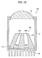
- Fig. 18 is a horizontal sectional view of a third left lamp unit according to the second exemplary embodiment of the present invention;
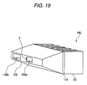
- Fig. 19 is a perspective view of a left light emitting unit of the third left lamp unit of Fig. 18 .
- Fig. 1 is a schematic diagram of a vehicle 10 on which a headlamp apparatus 11 according to an exemplary embodiment of the present invention is mounted.
- the headlamp apparatus 11 includes a headlamp section 12, an integrated controller 14, and a camera 16 (a vehicle position detector).
- the integrated controller 14 includes a central processing unit (CPU) for executing various calculating process operations, a read only memory (ROM) in which various control programs are stored in advance, a random access memory (RAM) which is utilized in order to store data and also used as a work area for executing relevant programs, and the like.
- the integrated controller 14 executes various control operations within the vehicle 10.
- the camera 16 includes an imaging element, for example, a charge coupled device (CCD) sensor, a complementary metal oxide semiconductor (CMOS) sensor.
- CMOS complementary metal oxide semiconductor
- the headlamp section 12 includes a headlamp controller 20, a right headlamp 22R, and a left headlamp 22L. Both the right headlamp 22R and the left headlamp 22L will be referred to as "headlamp 22" hereinafter as a general term where appropriate.
- the headlamp controller 20 includes a CPU, a ROM, and a RAM. The headlamp controller 20 controls light to be irradiated from the headlamp 22.
- Fig. 2 is a sectional view of the right headlamp 22R according to the first exemplary embodiment, taken along a horizontal plane and viewed from above. It should be understood that while the left headlamp 22L is constructed in a right-left symmetrical manner with respect to the right headlamp 22R, the right headlamp 22R will be explained in the below-mentioned explanations and a separate explanation of the left headlamp 22L will be omitted for brevity.
- the right headlamp 22R includes a transparent cover 30, a lamp body 32, an extension 34, a first lamp unit 36, and a second lamp unit 38R.
- the lamp body 32 is formed from a resin or the like in a cup shape having an elongate opening portion.
- the transparent cover 30 may be formed from a transparent resin.
- the transparent cover 30 is mounted on the lamp body 32 such that the light transition cover 30 may block the opening portion of the lamp body 32. Accordingly, a lamp chamber is formed by the lamp body 32 and the first transmission cover 30, and the extension 34, the first lamp unit 36 and the second lamp unit 38R are arranged in the lamp chamber.
- the extension 34 has an opening portion through which light irradiated from the first lamp unit 36 and the second lamp unit 38R passes.
- the extension 34 is fixed to the lamp body 32.
- the first lamp unit 36 is arranged on the outer side than the second right lamp unit 38R in the widthwise direction of the vehicle.
- the first lamp unit 36 is a projector-type lamp unit which forms a low beam distributing pattern.
- the first lamp unit 36 has a reflector 40, a light source bulb 42, and a shade 44.
- the reflector 40 is formed in a cup shape having a through hole in the center.
- the light source bulb 42 is an incandescent lamp, e.g., a halogen lamp, having a filament arranged therein.
- the light source bulb 42 may be a discharge lamp such as a metal halide bulb.
- the light source bulb 42 is inserted into the through hole of the reflector 40 such that the light source bulb 42 protrudes into an inner region of the reflector 40, and is fixed to the reflector 40.
- the reflector 40 has a curved inner surface to reflect the light emitted from the light source bulb 42 toward a forward region of the vehicle.
- the shade 44 shields a part of the light that is directly and forwardly emanated from the light source bulb 42.
- Fig. 3 is a sectional view of the second right lamp unit 38R, taken along a horizontal plane and viewed from above.
- the second right lamp unit 38R includes a holder 46, a projection lens 48, and a right light emitting unit 49R.
- the projection lens 48 is a plano-convex aspheric lens having a convex front surface and a flat rear surface.
- the projection lens 48 projects a light source image formed on a rear focal plane of the aspheric lens on a virtual vertical screen in a front of the lamp as an inverted image.
- the projection lens 48 is mounted on one opening portion of the holder 46 formed in the cylindrical shape.
- the right light emitting unit 49R includes a board 50, a first right light emitting device 52R1, a second right light emitting device 52R2, a third right light emitting device 52R3, a fourth right light emitting device 52R4, a fifth right light emitting device 52R5, and a heat sink 54.
- the configuration of the right light emitting unit 49R will now be described in detail in relation to Fig. 4 .
- Fig. 4 is a perspective view of the right light emitting unit 49R.
- the first right light emitting device 52R1 to fifth right light emitting device 52R5 are formed in rectangular shapes having the same heights with each other, and are arranged in a straight line form on the front surface of the board 50 such that these right light emitting devices 52R1 to 52R5 form a band shape in this order from the first right light emitting device 52R1 to the fifth right light emitting device 52R5.
- the first right light emitting device 52R1 to the fifth right light emitting device 52R5 have the same widths with each other.
- Each of the first right light emitting device 52R1 to the fifth right light emitting device 52R2 has a light emitting chip (not shown) and a thin film.
- the light emitting chip is a white light emitting diode having a square light emitting face of about 1 mm by 1 mm. It should also be noted that the light emitting chip is not limited to the white light emitting diode, and may be any other type of surface light emitting element, e.g., a laser diode, which emits light in a substantially point-shape.
- the thin film is provided such that the thin film covers the light emitting face of the light emitting chip.
- a rear focal point F of the projection lens 48 is positioned at a surface center position of the third right light emitting device 52R3.
- the heat sink 54 is made to have such a shape that a number of fins are made of a metal such as aluminum, and is mounted on the rear surface of the board 50.
- the board 50 is mounted on the other opening portion of the holder 46 in order that the first right light emitting device 52R1 to the fifth right light emitting device 52R5 are arranged within the holder 46 in this order from the first right light emitting device 52R1 to the fifth right light emitting device 52R5 from the left side. Since the respective right light emitting devices from the first right light emitting device 52R1 to the fifth right light emitting device 52R5 emit light, images of the respective right light emitting devices are projected on the virtual vertical screen of the forward area of the lamp.
- Fig. 5 is a sectional view of a second left lamp unit 38L of the left headlamp 22L, taken along a horizontal plane and viewed from above. It should also be understood that the same reference numerals will be employed as those for denoting structural elements of the second left lamp unit 38L, which are similar to those of the second right lamp unit 38R, and descriptions thereof will be omitted.
- the second left lamp unit 38L includes a holder 46, a projection lens 48, and a left light emitting unit 49L.
- the left light emitting unit 49L includes a board 56, a first left light emitting device 52L1, a second left light emitting device 52L2, a third left light emitting device 52L3, a fourth left light emitting device 52L4, and a heat sink 54.
- the configuration of the left light emitting unit 49L will now be described in detail in relation to Fig. 6 .
- Fig. 6 is a perspective view of the left light emitting unit 49L.
- the first left light emitting device 52L1 to fourth left light emitting device 52L4 are formed in rectangular shapes having the same heights with each other.
- the first left light emitting device 52L1 to the fourth left light emitting device 52L4 are arranged in a straight line form on the front surface of the board 56 such that the first to fourth left light emitting devices 52L1 to 52L4 form a band shape in this order from the first left light emitting device 52L1 to the fourth left light emitting device 52L4.
- the second left light emitting device 52L2 and the third left light emitting device 52L3 have the same widths with each other.
- first left light emitting device 52L1 and the fourth left light emitting device 52L4 have the same widths with each other, the widths of which are wider than the widths of the second left light emitting device 52L2 and the third left light emitting device 52L3. Similar to the above-described structural point of the right light emitting unit 49R, each of the first left light emitting device 52L1 to the fourth left light emitting device 52L4 has both a light emitting chip (not shown) and a thin film.
- a rear focal point F of the projection lens 48 is positioned at a center of a boundary line between the second left light emitting device 52L2 and the third left light emitting device 52L3.
- the heat sink 54 is mounted on the rear surface of the board 56.
- the board 56 is mounted on the other opening portion of the holder 46 in order that the first left light emitting device 52L1 to the fourth left light emitting device 52L4 are arranged within the holder 46 in this order from the first left light emitting device 52L1 to the fourth left light emitting device 52L4 from the left side. Since the respective left light emitting devices from the first left light emitting device 52L1 to the fourth left light emitting device 52L4 emit light, images of the respective left light emitting devices are projected on the virtual vertical screen in front of the lamp.
- first right light emitting device 52R1 to the fifth right light emitting device 52R5, and the first left light emitting device 52L1 to the fourth left light emitting device 52L4 will be referred to as "light emitting device 52" as a general term where appropriate.
- Fig. 7 is a diagram illustrating a light distributing pattern to be formed on a virtual vertical screen arranged, e.g., at a position 25 m in front of the vehicle 10 by forwardly irradiating light from the right headlamp 22R and the left headlamp 22L.
- a low beam distributing pattern PL is formed by the first lamp unit 36.
- the low beam distributing pattern PL corresponds to a low beam distributing pattern of a left light distribution, and an upper edge thereof has a first cutoff line CL1, a second cutoff line CL2, and a third cutoff line CL3.
- the first cutoff line CL 1 to the third cutoff line CL3 extend along the horizontal direction and create a step across the line V-V.
- the line V-V is a vertical line which passes through the vanishing point H-V in the forward direction from the lamp.
- the first cutoff line CL1 is extended along the horizontal direction, which is located on the right side from the line V-V and lower than the line H-H.
- the first cutoff line CL1 is utilized as a cutoff line for an oncoming vehicle lane.
- the third cutoff line CL3 is obliquely extended at an inclination angle of about 15 degrees from a left end portion of the first cutoff line CL1 toward an upper left direction.
- the second cutoff line CL2 is extended over the line H-H on the left side from a cross point between the line H-H and third cutoff line CL3.
- the second cutoff line CL2 is utilized as a cutoff line for the vehicle lane.
- a hot zone HZ corresponding to a high luminous intensity area is formed such that the elbow point E is surrounded along a slightly left direction.
- An additional light distributing pattern PA is formed by light irradiated from the second right lamp unit 38R and light irradiated from the second left lamp unit 38L.
- each of the second right lamp unit 38R and the second left lamp unit 38L may function as an additional lamp unit which forms the additional light distributing pattern PA.
- each of the second right lamp unit 38R and the second left lamp unit 38L may function as a high beam lamp unit.
- the additional light distributing pattern PA is formed in a band shape which is extended along the horizontal direction and includes the horizontal line such that a lower end of the additional light distributing pattern PA is positioned on the first cutoff line CL1.
- the additional light distributing pattern PA is formed by combining a right additional light distributing pattern PAR formed by the second right lamp unit 38R with a left additional light distributing pattern PAL formed by the second left lamp unit 38L.
- Fig. 8A is a diagram illustrating the right additional light distributing pattern PAR.
- the right additional light distributing pattern PAR has the same outer shape as that of the additional light distributing pattern PA.
- the right additional light distributing pattern PAR is divided into 5 areas. It should also be understood that these 5 areas will be sequentially referred to as a first right partial region PAR1, a second right partial region PAR2, a third right partial region PAR3, a fourth right partial region PAR4, and a fifth right partial region PAR5 from the right-sided partial region, and will be referred as "right partial region” as a general term where appropriate.
- Each of the first right partial region PAR1 to the fifth right partial region PAR5 is formed as a projection image where each of the first right light emitting device 52R1 to the fifth right light emitting device 52R5 is employed as a light source image.
- the first right partial region PAR1 to the fifth right partial region PAR5 are provided such that luminous intensity of irradiation light irradiated to each of the right partial regions PAR1 to PAR5 can be increased and/or decreased by adjusting the luminous intensity of a corresponding one of the first right light emitting device 52R1 to the fifth right emitting element 52R5.
- the first right partial region PAR1 to the fifth right partial region PAR5 are formed as rectangular shapes whose heights and widths are equal to each other respectively.
- the respective first right partial region PAR1 to fifth right partial region PAR5 are located adjacent to each other on dividing lines which are extended along the vertical direction.
- the shapes of the first right partial region PAR1 to the fifth right partial region PAR5 are not limited only to rectangular shapes, but may be made from other shapes, for example, trapezoids or parallelograms.
- Fig. 8B is a diagram illustrating the left additional light distributing pattern PAL.
- the left additional light distributing pattern PAL has the same outer shape as that of the additional light distributing pattern PA.
- the left additional light distributing pattern PAL is divided into 4 areas. It should also be understood that these 4 areas will be sequentially referred to as a first left partial region PAL1, a second left partial region PAL2, a third left partial region PAL3, and a fourth left partial region PAL4 from the right-sided partial region, and will be referred as "left partial region" as a general term where appropriate.
- Each of the first left partial region PAL1 to the fourth left partial region PAL4 is formed as a projection image where each of the first left light emitting device 52L1 to the fourth left light emitting device 52L4 is employed as a light source image.
- the first left partial region PAL1 to the fourth left partial region PAL4 are provided such that luminous intensity of irradiation light irradiated to each of the left partial regions PAL1 to PAL4 can be increased and/or decreased by adjusting the luminous intensity of a corresponding one of the first left light emitting device 52L1 to the fourth left light emitting device 52L4.
- the first left partial region PAL1 to the fourth left partial region PAL3 are formed as rectangular shapes whose heights and widths are equal to each other respectively.
- the second left partial region PAL2 and the third left partial region PAL3 have the same widths with each other.
- the first left partial region PAL1 and the fourth left partial region PAL have the same widths with each other, and also have wider widths than those of the second left partial region PAL2 and the third left partial region PAL3.
- the respective first left partial region PAL1 to fourth left partial region PAL4 are located adjacent to each other on dividing lines which are extended along the vertical direction. It should also be noted that the shapes of the first left partial region PAL1 to the fourth left partial region PAL4 are not limited only to rectangular shapes, but may be made from other shapes, for example, trapezoids or parallelograms.
- Fig. 8C is a diagram illustrating an additional light distributing pattern PA produced by combining the right additional light distributing patterns PAR with the left additional light distributing patterns PAL.
- outer shapes and dividing lines of the right additional light distributing patterns PAR are illustrated by wide lines, whereas outer shapes and dividing lines of the left additional light distributing patters PAL are illustrated by narrow lines.
- the second right partial region PAR2 is partially overlapped with the first left partial region PAL1 and the second left partial region PAL2, respectively.
- the third right partial region PAR3 is partially overlapped with the second left partial region PAL2 and the third left partial region PAL3, respectively.
- the fourth right partial region PAR4 is partially overlapped with the third left partial region PAL3 and the fourth left partial region PAL4, respectively.
- the additional light distributing pattern PA is formed such that the dividing lines of the right additional light distributing patterns PAR and the dividing lines of the left additional light distributing patterns PAL alternately appear in accordance with advances thereof along the horizontal direction.
- partial regions of the additional light distributing pattern PA which are segmented by the dividing lines of the right additional light distributing patterns PAR and the dividing lines of the left additional light distributing patterns PAL, will be defined as a first partial region PA1, a second partial region PA2, a third partial region PA3, a fourth partial region PA4, a fifth partial region PA5, a sixth partial region PA6, a seventh partial region PA7, and an eighth partial region PA8 from the right side.
- an intermediate beam mode is provided.
- a method for controlling the headlamp 22 when the intermediate beam mode is selected is selected.
- Fig. 9 is a diagram illustrating a relationship of various positions of oncoming vehicles with respect to the right additional light distributing patterns PAR, the left additional light distributing patterns PAL and the additional light distributing patterns PA during the intermediate beam mode.
- An intermediate beam switch (not shown) is provided in the vehicle 10 in addition to the high beam switch (not shown). When the intermediate beam switch is turned on, an intermediate beam ON signal is output to the headlamp controller 10. When the headlamp controller 20 receives the intermediate beam ON signal, light is irradiated in the intermediate beam mode by driving the right headlamp 22R and the left headlamp 22L.
- the integrated controller 14 determines whether an oncoming vehicle with a headlamp turned on is present by analyzing image data entered from the camera 16. When there is such an oncoming vehicle whose headlamp is turned on, the integrated controller 14 specifies a position of the oncoming vehicle by using the position of the headlamp acquired by analyzing the image data.
- the integrated controller 14 outputs positional data to the headlamp controller 20, while the positional data indicates the position of the oncoming vehicle whose headlamp being turned on.
- the headlamp controller 20 predicts that the oncoming vehicle is located within a right partial region including the position indicated by the positional data, and thus, turns off the light emitting device 52 which forms the above-described right partial region.
- the headlamp controller 20 may alternatively decrease luminous intensity of irradiation light of the light emitting device 52 for forming the right partial region in which it is predicted that the oncoming vehicle is present, such that the above-described luminous intensity of the light emitting device 52 becomes lower than a normal luminous intensity of the light emitting device 52 in which it is predicted that a vehicle is not present.
- the headlamp controller 20 turns off the light emitting device 52 for forming a left partial region in which it is predicted that a vehicle is present. It should also be noted that instead of turning off the light emitting device 52, the headlamp controller 20 may alternatively decrease the luminous intensity of the irradiation light of the light emitting device 52 for forming the left partial region in which it is predicted that the oncoming vehicle is present, such that the above-described luminous intensity of the light emitting device 52 becomes lower than a normal luminous intensity of the light emitting device 52 in which it is predicted that the vehicle is not present. As previously described, the irradiation of the light to the oncoming vehicle can be suppressed based upon the additional light distributing pattern PA, so that glare can be suppressed for a driver of the oncoming vehicle.
- the integrated controller 14 may specify a position of a pedestrian by using photographed image data. Further, the headlamp controller 20 may control turning on of the light emitting device 52 such that the luminous intensity of the irradiation light irradiated to both the right partial region and the left partial region which include the positions of the pedestrians are lower than the normal luminous intensity of the irradiation light.
- the headlamp controller 20 determines that an oncoming vehicle 2 is located at a first position which bridges the dividing line between the second left partial region PAL2 and the third left partial region PAL3, the headlamp controller 20 turns off the third right light emitting device 52R3 for forming the third right partial region PAR3. Also, the headlamp controller 20 turns off both the second left light lighting element 52L2 for forming the second left partial region PAL2, and the third left light lighting element 52L3 for forming the third left partial region PAL3. As a result, as to the additional light distributing pattern PA, the light is not irradiated to the fourth partial region PA4 and the fifth partial region PA5, so that this portion becomes dark.
- a black area indicates an area to which light is not irradiated from both the second right lamp unit 38R and the second left lamp unit 38L.
- a hatched area indicates such an area to which light is irradiated from one of the second right lamp unit 38R and the second left lamp unit 38L.
- the headlamp controller 20 determines that the oncoming vehicle 2 is located at a second position which bridges the dividing line between the second right partial region PAR2 and the third right partial region PAR3, the headlamp controller 20 turns off the second left light emitting device 52L2 for forming the second left partial region PAL2, and further, the headlamp controller 20 turns off both the second right light lighting element 52R2 for forming the second left partial region PAR2, and the third right light lighting element 52R3 for forming the third right partial region PAR3.
- the additional light distributing pattern PA the light is not irradiated to the third partial region PA3 and the fourth partial region PA4, so that this portion becomes dark.
- the headlamp controller 20 determines that the oncoming vehicle 2 is located at a third position which bridges the dividing line between the second left partial region PAL2 and the first left partial region PAL1, the headlamp controller 20 turns off the second right light emitting device 52R2 for forming the second right partial region PAR2.
- the headlamp controller 20 turns off both the second left light lighting element 52L2 for forming the second left partial region PAL2, and the first left light lighting element 52L1 for forming the first left partial region PAL1.
- the additional light distributing pattern PA the light is not irradiated to the second partial region PA2 and the third partial region PA3, so that this portion becomes dark conditions.
- the headlamp controller 20 determines that the oncoming vehicle 2 is located at a fourth position which bridges the dividing line between the first right partial region PAR1 and the second right partial region PAR2, the headlamp controller 20 turns off the first left light emitting device 52L1 for forming the first left partial region PAL1, and also, the headlamp controller 20 turns off both the second right light lighting element 52R2 for forming the second right partial region PAR2, and the first right light lighting element 52R1 for forming the first right partial region PAR1.
- the additional light distributing pattern PA the light is not irradiated to the first partial region PA1 and the second partial region PA2, so that this portion becomes dark.
- the third partial region PA3 becomes lighter than both the first partial region PA1 and the second partial region PA2, and also, becomes darker than the other partial regions which are predicted as partial regions in which the oncoming vehicle is not present.
- the headlamp controller 20 determines that the oncoming vehicle 2 is located at a fifth position which is positioned in the vicinity of a center of the first right partial region PAR1 along the horizontal direction, the headlamp controller 20 turns off the first right light emitting device 52R1 for forming the first right partial region PAR1. Also, the headlamp controller 20 turns off the first left light emitting device 52L1 for forming the first left partial region PAL1. As a result, as to the additional light distributing pattern PA, light is not irradiated to the first partial region PA1, so that the partial region PA1 becomes dark.
- the headlamp controller 20 controls turning on of the light emitting device 52 such that right and left positional relationships from the second position to the fifth position are inverted with respect to the right and left directions in response to existing positions of the oncoming vehicle 2.
- Fig. 10 is a diagram illustrating a relationship between the additional light distributing patterns PA and the respective positions of the oncoming vehicle when the intermediate beam mode is selected in a comparative configuration in which a right additional light distributing pattern PAR and a left additional light distributing pattern PAL are divided into the same shapes, such that right partial regions and left partial regions share the same partial regions PA11 to PA15. Similar to the case described above, in the case that light emitting devices for forming partial regions where the oncoming vehicle 2 is present in the intermediate beam mode are turned off, as indicated in Fig.
- both the 12th partial region PA12 and the 13th partial region PA13 are brought into dark conditions, which correspond to the second partial region PA2 to the fifth partial region PA5.
- both the 12th partial region PA12 and the 11th partial region PA11 are brought into dark conditions, which correspond to the first partial region PA1 to the third partial region PA3.
- Fig. 11 is a sectional view of a right headlamp 60R according to a second exemplary embodiment of the present invention, taken along a horizontal plane and viewed from above.
- a configuration of a vehicle according to the second exemplary embodiment is similar to the configuration of the vehicle 10 according to the first exemplary embodiment except that the right headlamp 60R and a left headlamp 60L are provided instead of the right headlamp 22R and the left headlamp 22L.
- the same reference numerals will be used to denote structural elements of the vehicle of the second exemplary embodiment that are similar to those of the vehicle 10 according to the first exemplary embodiment.
- the left headlamp 60L is constructed in a right-left symmetrical manner with respect to the right headlamp 60R. Therefore, the right headlamp 60R will be explained in detail below and a detailed explanation of the left headlamp 60L will be omitted.
- the right headlamp 60R is configured in a similar manner to the right headlamp 22R according to the first exemplary embodiment except that instead of the second right lamp unit 38R, a second right lamp unit 62R and a third right lamp unit 64R are provided.
- Fig. 12 is a sectional view of the second right lamp unit 62R, taken along a horizontal plane and viewed from above.
- the second right lamp unit 62R includes a holder 70, a projection lens 72, and a right light emitting unit 74R.
- the projection lens 72 is a plano-convex aspheric lens.
- the projection lens 72 is mounted on one opening portion of the holder 70 formed in a cylindrical shape.
- the right light emitting unit 74R includes a block 76, a board 78, a first right light emitting device 80R1, a third right light emitting device 80R3, a fifth right light emitting device 80R5, and a heat sink 82.
- a first optical path 76a, a second optical path 76b, and a third optical path 76c, which correspond to through holes, are formed in the block 76.
- An inner plane of each of the first optical path 76a to the third optical path 76c is constructed of a mirror plane.
- One edge plane of the block 76, in which opening portions of the through holes are formed, is fixed to a front surface of the board 78.
- the first right light emitting device 80R1, the third right light emitting device 80R3, and the fifth right light emitting device 80R5 are arranged at respective positions corresponding to the respective opening portions of the first optical path 76a, the second optical path 76b, and the third optical path 76c on a front surface of the board 78.
- Each of the light emitting devices 80R1, 80R3, 80R5 has a light emitting chip (not shown) which is a white light emitting diode having a square light emitting face of about 1 mm by 1 mm.
- the heat sink 82 is made to have such a shape such that a number of fins are made of a metal such as aluminum, and is mounted on the rear surface of the board 78.
- Fig. 13 is a perspective view of the right light emitting unit 74R.
- the first optical path 76a to the third optical path 76c are arranged such that the respective opening portions thereof are arranged in a row along a lateral direction.
- the respective opening portions of the first optical path 76a to the third optical path 76c are formed in rectangular shapes whose heights and whose widths are equal to each other, respectively.
- a rear focal point F of the projection lens 72 is positioned at a center of the opening portion of the second optical path 76b.
- the board 78 is mounted on the other opening portion of the holder 70 in order that the block 76 may be arranged within the holder 70, so that the board 78 is fixed.
- the right light emitting device 74R is fixed such that the first right light emitting device 80R1, the third right light emitting device 80R3, and the fifth right light emitting device 80R5 are arranged in this order from the left side.
- the irradiation light thereof is reflected on the inner plane of the first optical path 76a, travels to the opening portion thereof, and then, the irradiation light causes a first right partial region PAR1 to be formed as a projection image of such an image of the opening portion.
- the third right light emitting device 80R3 is turned on, the irradiation light thereof is reflected on the inner plane of the second optical path 76b, travels to the opening portion thereof, and then, the irradiation light causes a third right partial region PAR3 to be formed as a projection image of such an image of the opening portion.
- the irradiation light thereof is reflected on the inner plane of the third optical path 76c, travels to the opening portion thereof, and then, the irradiation light causes a fifth right partial region PAR5 to be formed as a projection image of such an image of the opening portion.
- Fig. 14 is a sectional view of the third right lamp unit 64R, taken along a horizontal plane and viewed from above. It should also be understood that the same reference numerals will be used as those for denoting structural elements of the third right lamp unit 64R, which are similar to those of the above-described exemplification, and descriptions thereof will be omitted.
- the third right lamp unit 64R includes the holder 70, the projection lens 72, and a right light emitting unit 94R.
- the right light emitting unit 94R includes a block 96, a board 98, a second right light emitting device 80R2, a fourth right light emitting device 80R4, and the heat sink 82.
- a first optical path 96a and a second optical path 96b are formed in the block 96, while the first and second optical paths 96a, 96b correspond to through holes.
- the respective inner planes of the first optical path 96a and the second optical path 96b are constructed by mirror planes.
- One edge plane of the block 96, where the opening portions of these through holes are formed, is fixed to a front surface of the board 98.
- the second right light emitting device 80R2 is arranged at a position corresponding to the opening portion of the first optical path 96a, and the fourth right light emitting device 80R4 is arranged at a position corresponding to the opening portion of the second optical path 96b.
- Each of the right light emitting devices 80R2, 80R4 includes a light emitting chip (not shown) such as a white light emitting diode having a square light emitting face of about 1 mm by 1 mm.
- Fig. 15 is a perspective view of the right light emitting unit 94R.
- a first optical path 96a and a second optical path 96b are arranged such that the respective opening portions thereof are arranged in a row along a lateral direction.
- the respective opening portions of the first optical path 96a and the second optical path 96b have the same heights and the same widths with each other, respectively.
- a rear focal point F of the projection lens 72 is positioned at a center between the opening portion of the first optical path 96a and the opening portion of the second optical path 96b.
- the board 98 is mounted on the other opening portion of the holder 70 in order that block 96 may be arranged within the holder 70, so that the board 98 is fixed.
- the right light emitting device 94R is fixed such that the second right light emitting device 80R2 and the fourth right light emitting device 80R4 are arranged in order from the left side.
- the irradiation light thereof is reflected on the inner plane of the first optical path 96a, travels to the opening portion thereof, and then, the irradiation light causes a second right partial region PAR2 to be formed as a projection image of an image of the opening portion.
- the fourth right light emitting device 80R4 is turned on, the irradiation light thereof is reflected on the inner plane of the second optical path 96b, travels to the opening portion thereof, and then, the irradiation light causes a fourth right partial region PAR4 to be formed as a projection image of an image of the opening portion.
- a right additional light distributing pattern PAR can be formed which is divided to be arranged such that the divided partial regions are arranged in a row in this order from the first right partial region PAR1 to the fifth right partial region PAR5 along the horizontal direction from the right side.
- Fig. 16 is a sectional view of the second left lamp unit 62L, taken along a horizontal plane and viewed from above.
- the second left lamp unit 62L includes the holder 70, the projection lens 72, and a left light emitting unit 74L.
- the left light emitting unit 74L includes a block 102, a board 104, a first left light emitting device 80L1, a third left light emitting device 80L3, and a heat sink 82.
- a first optical path 102a and a second optical path 102b are formed in the block 102, while the first and second optical paths 102a, 102b correspond to through holes.
- the respective inner planes of the first optical path 102a and the second optical path 102b are constructed by mirror planes.
- One edge plane of the block 102, where the opening portions of these through holes are formed, is fixed to a front surface of the board 102.
- both the first left light emitting device 80L1 and the third left light emitting device 80L3 are arranged at positions corresponding to the opening portions of the first optical path 102a and the second optical path 102b.
- Each of the first and third left light emitting devices 80L1, 80L3 includes a light emitting chip (not shown) such as a white light emitting diode having a square light emitting face of about 1 mm by 1 mm.
- Fig. 17 is a perspective view of the left light emitting unit 74L.
- the first optical path 102a and the second optical path 102b are arranged such that the respective opening portions thereof are arranged in a row along a lateral direction.
- the respective opening portions of the first optical path 102a and the second optical path 102b are formed in rectangular shapes whose heights are equal to each other, respectively.
- the opening portion of the first optical path 102a has a wider width than a width of the opening of the second optical path 102b.
- a rear focal point F of the projection lens 72 is located at an edge of the opening portion of the second optical path 102b on the side of the first optical path 102a.
- the board 102 is mounted on the other opening portion of the holder 70 in order that the block 102 may be arranged within the holder 70, so that the board 104 is fixed.
- the left right light emitting device 74L is fixed such that the first left light emitting device 80L1 and the third left light emitting device 80L3 are arranged in this order from the left side.
- the irradiation light thereof When the first left light emitting device 80L1 is turned on, the irradiation light thereof is reflected on the inner plane of the first optical path 102a, travels to the opening portion thereof, and then, the irradiation light causes a first left partial region PAL1 to be formed as a projection image of an image of the opening portion.
- the third left light emitting device 80L3 When the third left light emitting device 80L3 is turned on, the irradiation light thereof is reflected on the inner plane of the second optical path 102b, travels to the opening portion thereof, and then, the irradiation light causes a third right partial region PAL3 to be formed as a projection image of an image of the opening portion.
- Fig. 18 is a sectional view of the third right lamp unit 64L, taken along a horizontal plane and viewed from above. It should also be understood that the same reference numerals will be employed as those for denoting structural elements of the third right lamp unit 64L, which are similar to those of the above-described example, and descriptions thereof will be omitted.
- the third left lamp unit 64L includes the holder 70, the projection lens 72, and a left light emitting unit 94L.
- the left light emitting unit 94L includes a block 108, a board 110, a second left light emitting device 80L2 and a fourth left light emitting device 80L4, and the heat sink 82.
- a first optical path 108a and a second optical path 108b are formed in the block 108, while the first and second optical paths 108a, 108b correspond to through holes.
- the respective inner planes of the first optical path 108a and the second optical path 108b are constructed by mirror planes.
- One edge plane of the block 108, where the opening portions of these through holes are formed, is fixed to a front surface of the board 110.
- the second left light emitting device 80L2 is arranged at a position corresponding to the opening portion of the first optical path 108a, and the fourth left light emitting device 80L4 is arranged at a position corresponding to the opening portion of the second optical path 108b.
- Each of the left light emitting devices 80L2, 80L4 includes a light emitting chip (not shown) such as a white light emitting diode having a square light emitting face of about 1 mm by 1 mm.
- Fig. 19 is a perspective view of the left light emitting unit 94L.
- a first optical path 108a and a second optical path 108b are arranged such that the respective opening portions thereof are arranged in a row along a lateral direction, while the respective opening portions of the first optical path 108a and the second optical path 108b are formed in rectangular shapes having the same heights with each other.
- the opening portion of the first optical path 108a has a width which is narrower than a width of the opening portion of the second optical path 108b.
- a rear focal point F of the projection lens 72 is located on an edge of the opening portion of the first optical path 108a on the side of the second optical path 108b.
- the board 110 is mounted on the other opening portion of the holder 70 in order that block 108 may be arranged within the holder 70, so that the board 110 is fixed.
- the left light emitting device 94L is fixed such that the second left light emitting device 80L2 and the fourth left light emitting device 80L4 are arranged in this order from the left side.
- the irradiation light thereof is reflected on the inner plane of the first optical path 108a, travels to the opening portion thereof, and then, the irradiation light causes a second left partial region PAL2 to be formed as a projection image of an image of the opening portion.
- the fourth left light emitting device 80L4 is turned on, the irradiation light thereof is reflected on the inner plane of the second optical path 108b, travels to the opening portion thereof, and then, the irradiation light causes a fourth left partial region PAL4 to be formed as a projection image of an image of the opening portion.
- a left additional light distributing pattern PAL can be formed which is sub-divided to be arranged such that the divided partial regions are arranged in a row in this order from the first left partial region PAL1 to the fourth left partial region PAL4 along the horizontal direction from the right side.
- the additional light distributing pattern PA is formed such that the dividing lines of the right additional light distributing patterns PAR and the dividing lines of the left additional light distributing patterns PAL alternately appear in accordance with advances thereof along the horizontal direction.
- the vehicle headlamp apparatus can suppress the occurrence of a forward region of the vehicle in which a driver of a vehicle has difficulty seeing, and can also suppress glare experienced by preceding vehicles and pedestrians.
- a vehicle headlamp apparatus includes a low beam lamp unit which forms a low beam distribution pattern, a first additional lamp unit which forms a first additional light distributing pattern at least partially above a cutoff line of the low beam distributing pattern, a second additional lamp unit which forms a second additional light distributing pattern overlapping with the first additional light distributing pattern, and a controller.
- the first additional light distributing pattern includes at least one first partial region, and the first additional lamp unit is configured such that a luminous intensity of a light to be irradiated toward the first partial region is adjustable.
- the second additional light distributing pattern includes at least one second partial region which partially overlaps with the first partial region, and the second additional lamp unit is configured such that a luminous intensity of a light to be irradiated toward the second partial region is adjustable.
- the controller controls the first additional lamp unit to adjust the luminous intensity of the light to be irradiated toward the first partial region and controls the second additional lamp unit to adjust the luminous intensity of the light to be irradiated toward the second partial region.
- At least a portion of the first additional light distributing pattern is divided into a plurality of the first partial regions such that the plurality of the first partial regions are arranged in a row
- at least a portion of the second additional light distributing pattern that overlaps with the first additional light distributing pattern is divided in to a plurality of the second partial regions such that the plurality of the second partial regions are arranged in a row parallel to the row of the plurality of the first partial regions and such that dividing lines of the plurality of the first partial regions and dividing lines of the plurality of the second partial regions are alternately arranged.
- the luminous intensity is independently adjustable for each of the plurality of the first partial regions and for each of the plurality of the second partial regions.
- the portion of the first additional light distributing pattern and the portion of the second additional light distributing pattern are formed in an area including a horizontal line, and the row of the plurality of the first partial regions and the row of the plurality of the second partial regions are extend along the horizontal line.
- the luminous intensity of the irradiation light irradiated to the area including the horizontal line is reduced, if it is advantageous, so that glare caused to the preceding vehicle and the pedestrian can be effectively suppressed.
- the vehicle headlamp apparatus may further include a vehicle position detector which detects a position of a vehicle in a forward region of the vehicle headlamp apparatus. Based on the position of the vehicle detected by the vehicle position detector, the controller determines whether the vehicle is present in the first partial region, and if the vehicle is present in the first partial region, the controller controls the first additional lamp unit such that the luminous intensity of the light to be irradiated toward the first partial region is lowered.
- a vehicle position detector which detects a position of a vehicle in a forward region of the vehicle headlamp apparatus. Based on the position of the vehicle detected by the vehicle position detector, the controller determines whether the vehicle is present in the first partial region, and if the vehicle is present in the first partial region, the controller controls the first additional lamp unit such that the luminous intensity of the light to be irradiated toward the first partial region is lowered.
- the controller determines whether the vehicle is present in the second partial region, and if the vehicle is present in the second partial region, the controller controls the second additional lamp unit such that the luminous intensity of the light to be irradiated toward the second partial region is lowered.
- a vehicle headlamp apparatus comprises: a first headlamp including a first low-beam lamp unit having a light source bulb and a reflector, and a first additional lamp unit having at least four rectangular first light emitting devices arranged side by side in a row, each of the rectangular first light emitting devices having a same height and a same width; and a second headlamp including a second low-beam lamp unit having a light source bulb and a reflector, and a second additional lamp unit having at least three rectangular second light emitting devices arranged side by side in a row, each of the rectangular second light emitting devices having a same height, an outside device width of each of the rectangular second light emitting devices on outside ends of the row being the same and an inside device width of each of the rectangular second light emitting devices on the inside of the row being the same, the outside device width being greater than the inside device width, wherein light emitted from one of the second light emitting devices partially overlaps light emitted from a corresponding two of
Landscapes
- Engineering & Computer Science (AREA)
- General Engineering & Computer Science (AREA)
- Physics & Mathematics (AREA)
- Microelectronics & Electronic Packaging (AREA)
- Optics & Photonics (AREA)
- Mechanical Engineering (AREA)
- Lighting Device Outwards From Vehicle And Optical Signal (AREA)
- Non-Portable Lighting Devices Or Systems Thereof (AREA)
Applications Claiming Priority (1)
| Application Number | Priority Date | Filing Date | Title |
|---|---|---|---|
| JP2008062672A JP5255301B2 (ja) | 2008-03-12 | 2008-03-12 | 車両用前照灯装置 |
Publications (3)
| Publication Number | Publication Date |
|---|---|
| EP2101107A2 true EP2101107A2 (fr) | 2009-09-16 |
| EP2101107A3 EP2101107A3 (fr) | 2011-03-23 |
| EP2101107B1 EP2101107B1 (fr) | 2018-09-19 |
Family
ID=40749847
Family Applications (1)
| Application Number | Title | Priority Date | Filing Date |
|---|---|---|---|
| EP09003562.7A Ceased EP2101107B1 (fr) | 2008-03-12 | 2009-03-11 | Appareil de phare de véhicule |
Country Status (3)
| Country | Link |
|---|---|
| US (1) | US8979336B2 (fr) |
| EP (1) | EP2101107B1 (fr) |
| JP (1) | JP5255301B2 (fr) |
Cited By (21)
| Publication number | Priority date | Publication date | Assignee | Title |
|---|---|---|---|---|
| EP2280215A3 (fr) * | 2009-07-31 | 2011-04-27 | Zizala Lichtsysteme GmbH | Phare de véhicule automobile à LED pour la production d'une répartition de lumière dynamique |
| WO2011114270A1 (fr) * | 2010-03-19 | 2011-09-22 | Koninklijke Philips Electronics N.V. | Ensemble éclairage pour véhicule |
| WO2012109681A1 (fr) * | 2011-02-16 | 2012-08-23 | Zizala Lichtsysteme Gmbh | Module d'éclairage led |
| EP2567867A2 (fr) | 2011-09-06 | 2013-03-13 | Koito Manufacturing Co., Ltd. | Phare de véhicule et son procédé de commande |
| EP2586659A1 (fr) * | 2011-10-28 | 2013-05-01 | Koito Manufacturing Co., Ltd. | Phare de véhicule |
| EP2591952A3 (fr) * | 2011-11-08 | 2013-10-16 | Koito Manufacturing Co., Ltd. | Appareil de commande de phare, système de commande de phare, système de phare et procédé de commande de phare |
| CN104110631A (zh) * | 2014-07-08 | 2014-10-22 | 奇瑞汽车股份有限公司 | 基于投影原理的智能前照灯 |
| CN104654175A (zh) * | 2013-11-22 | 2015-05-27 | 现代摩比斯株式会社 | 车辆用多阵列led芯片及具备该芯片的前照灯 |
| EP2818793A3 (fr) * | 2013-06-26 | 2015-08-12 | Stanley Electric Co., Ltd. | Appareil électroluminescent et système de phare de véhicule |
| EP2541130A3 (fr) * | 2011-06-29 | 2015-09-30 | Sharp Kabushiki Kaisha | Dispositif de projection de lumière et phare de véhicule comprenant un tel dispositif de projection de lumière |
| EP2982902A1 (fr) * | 2014-08-08 | 2016-02-10 | Automotive Lighting Reutlingen GmbH | Module lumineux de projection pour un phare de vehicule automobile |
| EP2786064B1 (fr) | 2012-12-20 | 2016-04-20 | Zizala Lichtsysteme GmbH | Unité d'éclairage pour un projecteur |
| CZ306483B6 (cs) * | 2015-11-20 | 2017-02-08 | Varroc Lighting Systems, s.r.o. | Světelné zařízení, zejména projektorový systém světlometu pro motorová vozidla |
| DE102015011623A1 (de) * | 2015-09-07 | 2017-03-09 | GM Global Technology Operations LLC (n. d. Ges. d. Staates Delaware) | Scheinwerfervorrichtung eines Fahrzeuges |
| WO2017050986A1 (fr) * | 2015-09-25 | 2017-03-30 | Audi Ag | Projection d'un motif lumineux pouvant être prédéfini |
| DE102015012568A1 (de) | 2015-09-25 | 2017-03-30 | GM Global Technology Operations LLC (n. d. Ges. d. Staates Delaware) | Scheinwerfervorrichtung für ein Fahrzeug und Verfahren zur Steuerung der Scheinwerfervorrichtung |
| CN107076382A (zh) * | 2014-10-02 | 2017-08-18 | 法雷奥照明公司 | 用于机动车辆的前灯的具有优化的光强轮廓的照明系统 |
| EP2690351A3 (fr) * | 2012-07-25 | 2018-03-07 | Koito Manufacturing Co., Ltd. | Phare de véhicule |
| CN108302453A (zh) * | 2016-07-06 | 2018-07-20 | Lg电子株式会社 | 车辆用灯泡 |
| CN112628683A (zh) * | 2019-10-09 | 2021-04-09 | 坦德科技股份有限公司 | 车用照明装置 |
| EP3865765A1 (fr) * | 2020-02-14 | 2021-08-18 | Tan de Tech Co., Ltd. | Dispositif d'éclairage pour véhicule |
Families Citing this family (44)
| Publication number | Priority date | Publication date | Assignee | Title |
|---|---|---|---|---|
| JP5233627B2 (ja) * | 2008-12-05 | 2013-07-10 | トヨタ自動車株式会社 | 車両用照明装置 |
| DE102009026571A1 (de) * | 2009-05-29 | 2010-12-02 | Robert Bosch Gmbh | Verfahren und Vorrichtung zur Fahrzeug gestützten Beleuchtung bei unzureichend beleuchteten Verkehrsumgebungen |
| JP5397186B2 (ja) * | 2009-11-24 | 2014-01-22 | スタンレー電気株式会社 | 車両用灯具 |
| JP5532310B2 (ja) | 2010-03-25 | 2014-06-25 | スタンレー電気株式会社 | 車両用灯具 |
| JP5588832B2 (ja) * | 2010-11-09 | 2014-09-10 | スタンレー電気株式会社 | 車両用照明灯具 |
| JP2012119193A (ja) | 2010-12-01 | 2012-06-21 | Sharp Corp | 発光装置、車両用前照灯、照明装置、及び車両 |
| JP5788194B2 (ja) | 2011-03-03 | 2015-09-30 | シャープ株式会社 | 発光装置、照明装置、及び車両用前照灯 |
| JP5692520B2 (ja) * | 2011-03-14 | 2015-04-01 | スタンレー電気株式会社 | 灯具ユニット |
| JP5719697B2 (ja) | 2011-06-10 | 2015-05-20 | 株式会社小糸製作所 | 車両の前照灯装置 |
| JP5779028B2 (ja) | 2011-07-26 | 2015-09-16 | 株式会社小糸製作所 | ヘッドランプの配光制御手段 |
| JP2013067343A (ja) | 2011-09-26 | 2013-04-18 | Koito Mfg Co Ltd | 車両用配光制御システム |
| EP2574502B1 (fr) | 2011-09-30 | 2019-10-30 | Koito Manufacturing Co., Ltd. | Système de commande de phare de véhicule |
| JP5869835B2 (ja) * | 2011-10-12 | 2016-02-24 | 株式会社小糸製作所 | 車両用前照灯制御システム |
| FR2984458B1 (fr) * | 2011-12-19 | 2018-03-09 | Valeo Vision | Module d'eclairage generateur d'un entrelacement de bandes lumineuses |
| FR2984457B1 (fr) * | 2011-12-19 | 2023-08-11 | Valeo Vision | Module d'eclairage comprenant au moins deux sources lumineuses installees de maniere sensiblement orthogonale |
| KR101398225B1 (ko) | 2012-12-27 | 2014-05-23 | 현대모비스 주식회사 | 차량용 헤드 램프 |
| JP2014172566A (ja) | 2013-03-12 | 2014-09-22 | Koito Mfg Co Ltd | 車両用前照灯システムおよび制御装置 |
| JP6048749B2 (ja) * | 2013-04-24 | 2016-12-21 | 本田技研工業株式会社 | 車両用灯火装置 |
| JP2015015104A (ja) * | 2013-07-03 | 2015-01-22 | スタンレー電気株式会社 | 光源装置、車両用前照灯、車両用前照灯システム |
| JP6235814B2 (ja) * | 2013-07-09 | 2017-11-22 | 株式会社小糸製作所 | 照明制御システム |
| KR101491283B1 (ko) * | 2013-07-24 | 2015-02-06 | 현대자동차주식회사 | 글래어프리하이빔 구현을 위한 차량용 헤드램프 |
| US10300840B2 (en) | 2014-02-04 | 2019-05-28 | Koito Manufacturing Co., Ltd. | Vehicle lamp control system |
| JP6236745B2 (ja) * | 2014-02-17 | 2017-11-29 | スタンレー電気株式会社 | 車両用灯具 |
| JP6270033B2 (ja) * | 2014-02-17 | 2018-01-31 | スタンレー電気株式会社 | 車両用灯具 |
| CN104890564A (zh) * | 2014-03-06 | 2015-09-09 | 鸿富锦精密工业(深圳)有限公司 | 车辆前照灯 |
| US20140211488A1 (en) * | 2014-03-31 | 2014-07-31 | Caterpillar Inc. | Method to control headlight of vehicle |
| JP2016107880A (ja) | 2014-12-08 | 2016-06-20 | スタンレー電気株式会社 | 車両用前照灯 |
| AT516965B1 (de) * | 2015-03-25 | 2016-12-15 | Zkw Group Gmbh | Beleuchtungsvorrichtung für Fahrzeugscheinwerfer |
| JP6545496B2 (ja) * | 2015-03-25 | 2019-07-17 | スタンレー電気株式会社 | 車両用前照灯の点灯制御装置、車両用前照灯システム |
| JP6663168B2 (ja) * | 2015-03-25 | 2020-03-11 | スタンレー電気株式会社 | 車両用前照灯の点灯制御装置、車両用前照灯システム |
| JP6674747B2 (ja) * | 2015-05-22 | 2020-04-01 | スタンレー電気株式会社 | 車両用前照灯システム |
| JP6635691B2 (ja) * | 2015-06-29 | 2020-01-29 | 株式会社小糸製作所 | 車両用灯具 |
| CN107735615B (zh) | 2015-06-29 | 2021-02-09 | 株式会社小糸制作所 | 车辆用灯具 |
| JP6697254B2 (ja) | 2015-12-18 | 2020-05-20 | スタンレー電気株式会社 | 車両用灯具 |
| KR20170076183A (ko) * | 2015-12-24 | 2017-07-04 | 에스엘 주식회사 | 차량용 적응형 헤드 램프 |
| DE102016203374B4 (de) * | 2016-03-02 | 2025-07-17 | Osram Gmbh | Matrix-beleuchtungs-modul |
| JP6796993B2 (ja) * | 2016-10-24 | 2020-12-09 | 株式会社小糸製作所 | 光学ユニット |
| JP6571734B2 (ja) * | 2017-09-04 | 2019-09-04 | トヨタ自動車株式会社 | 車両用照明装置 |
| DE102018103262B4 (de) * | 2018-02-14 | 2024-05-29 | Dr. Ing. H.C. F. Porsche Aktiengesellschaft | Verfahren zum Betreiben einer Beleuchtungsvorrichtung eines Kraftfahrzeugs |
| JP7061902B2 (ja) | 2018-03-12 | 2022-05-02 | スタンレー電気株式会社 | 車両用灯具 |
| FR3079468B1 (fr) * | 2018-04-03 | 2020-03-20 | Valeo Vision | Dispositif lumineux pour un vehicule automobile realisant une fonction d’ecriture au sol |
| US10611294B2 (en) * | 2018-06-29 | 2020-04-07 | Valeo North America, Inc. | Front lighting systems and methods |
| EP4044148B1 (fr) * | 2019-10-10 | 2025-06-04 | Koito Manufacturing Co., Ltd. | Dispositif de détection de position de véhicule, système de lampe de véhicule, et procédé de détection de position de véhicule |
| CN116568559A (zh) * | 2020-11-16 | 2023-08-08 | 株式会社小糸制作所 | 路面描绘装置 |
Citations (3)
| Publication number | Priority date | Publication date | Assignee | Title |
|---|---|---|---|---|
| JPH0481337A (ja) | 1990-07-24 | 1992-03-16 | Nissan Motor Co Ltd | 車両用前照灯装置 |
| JP2004231178A (ja) | 2003-01-30 | 2004-08-19 | Valeo Vision | 道路を変調照明する方法およびこの方法を実行するための車両用ヘッドライト |
| JP2006188224A (ja) | 2005-01-03 | 2006-07-20 | Ford Global Technologies Llc | 車両用暗視システム、光源操作システム及びその制御方法 |
Family Cites Families (25)
| Publication number | Priority date | Publication date | Assignee | Title |
|---|---|---|---|---|
| US5837994C1 (en) * | 1997-04-02 | 2001-10-16 | Gentex Corp | Control system to automatically dim vehicle head lamps |
| JP2002193025A (ja) * | 2000-12-27 | 2002-07-10 | Koito Mfg Co Ltd | 車両用前照灯装置 |
| JP3760118B2 (ja) * | 2001-08-01 | 2006-03-29 | 株式会社小糸製作所 | 車両用灯具の照射方向制御装置 |
| JP3989412B2 (ja) * | 2002-10-21 | 2007-10-10 | オリンパス株式会社 | 照明装置及び画像投影装置 |
| JP2004311101A (ja) * | 2003-04-03 | 2004-11-04 | Koito Mfg Co Ltd | 車両用前照灯及び半導体発光素子 |
| JP4264335B2 (ja) | 2003-12-05 | 2009-05-13 | 株式会社小糸製作所 | 車両用前照灯 |
| JP2005280681A (ja) * | 2004-03-05 | 2005-10-13 | Denso Corp | 車両用前照灯光軸方向自動調整装置 |
| JP4234074B2 (ja) * | 2004-07-15 | 2009-03-04 | 株式会社小糸製作所 | 車両用照明灯具 |
| JP4413762B2 (ja) * | 2004-12-07 | 2010-02-10 | 株式会社小糸製作所 | 車両用照明灯具 |
| US7815350B2 (en) * | 2005-04-21 | 2010-10-19 | Magna International Inc. | Headlamp with beam patterns formed from semiconductor light sources |
| US7258474B2 (en) * | 2005-04-21 | 2007-08-21 | Magna International Inc. | Headlamp with beam patterns formed from semiconductor light sources |
| FR2889288B1 (fr) * | 2005-07-26 | 2015-07-31 | Valeo Vision | Dispositif d'eclairage avec plusieurs modules optiques pour vehicule automobile |
| JP2007099222A (ja) * | 2005-10-07 | 2007-04-19 | Koito Mfg Co Ltd | 車両用照明装置 |
| JP4615417B2 (ja) * | 2005-10-13 | 2011-01-19 | 株式会社小糸製作所 | 車両用前照灯の灯具ユニット |
| JP4675874B2 (ja) * | 2006-01-20 | 2011-04-27 | 株式会社小糸製作所 | 車両用照明灯具 |
| JP4663548B2 (ja) * | 2006-02-24 | 2011-04-06 | 株式会社小糸製作所 | 車両用前照灯の灯具ユニット |
| FR2898402B1 (fr) * | 2006-03-07 | 2015-01-23 | Valeo Vision | Module optique pour projecteur automobile muni d'un element de deviation optique |
| US20080025037A1 (en) * | 2006-07-28 | 2008-01-31 | Visteon Global Technologies, Inc. | LED headlamp |
| JP4708285B2 (ja) * | 2006-08-04 | 2011-06-22 | トヨタ自動車株式会社 | 車両用ヘッドランプ |
| JP4349410B2 (ja) * | 2006-12-01 | 2009-10-21 | トヨタ自動車株式会社 | 車両用照明装置 |
| JP4349414B2 (ja) * | 2006-12-15 | 2009-10-21 | トヨタ自動車株式会社 | 車両用照明装置 |
| US7677777B2 (en) * | 2007-02-21 | 2010-03-16 | Magna International, Inc. | LED apparatus for world homologation |
| DE102007028658A1 (de) * | 2007-06-21 | 2008-12-24 | Hella Kgaa Hueck & Co. | Verfahren zum Steuern einer Scheinwerferanordnung für ein Fahrzeug mit separaten Scheinwerfern für ein Abblendlicht und ein Fernlicht |
| JP4881255B2 (ja) * | 2007-08-13 | 2012-02-22 | 株式会社小糸製作所 | 車両用前照灯 |
| JP5069985B2 (ja) | 2007-09-13 | 2012-11-07 | 株式会社小糸製作所 | 車両用前照灯の灯具ユニットおよび車両用前照灯 |
-
2008
- 2008-03-12 JP JP2008062672A patent/JP5255301B2/ja active Active
-
2009
- 2009-03-11 US US12/401,643 patent/US8979336B2/en active Active
- 2009-03-11 EP EP09003562.7A patent/EP2101107B1/fr not_active Ceased
Patent Citations (3)
| Publication number | Priority date | Publication date | Assignee | Title |
|---|---|---|---|---|
| JPH0481337A (ja) | 1990-07-24 | 1992-03-16 | Nissan Motor Co Ltd | 車両用前照灯装置 |
| JP2004231178A (ja) | 2003-01-30 | 2004-08-19 | Valeo Vision | 道路を変調照明する方法およびこの方法を実行するための車両用ヘッドライト |
| JP2006188224A (ja) | 2005-01-03 | 2006-07-20 | Ford Global Technologies Llc | 車両用暗視システム、光源操作システム及びその制御方法 |
Cited By (36)
| Publication number | Priority date | Publication date | Assignee | Title |
|---|---|---|---|---|
| EP2280215A3 (fr) * | 2009-07-31 | 2011-04-27 | Zizala Lichtsysteme GmbH | Phare de véhicule automobile à LED pour la production d'une répartition de lumière dynamique |
| US10227033B2 (en) | 2010-03-19 | 2019-03-12 | Lumileds Llc | Lighting assembly for vehicle |
| WO2011114270A1 (fr) * | 2010-03-19 | 2011-09-22 | Koninklijke Philips Electronics N.V. | Ensemble éclairage pour véhicule |
| US11643006B2 (en) | 2010-03-19 | 2023-05-09 | Lumileds Llc | Lighting assembly for vehicle |
| US11260788B2 (en) | 2010-03-19 | 2022-03-01 | Lumileds Llc | Lighting assembly for vehicle |
| WO2012109681A1 (fr) * | 2011-02-16 | 2012-08-23 | Zizala Lichtsysteme Gmbh | Module d'éclairage led |
| EP2541130A3 (fr) * | 2011-06-29 | 2015-09-30 | Sharp Kabushiki Kaisha | Dispositif de projection de lumière et phare de véhicule comprenant un tel dispositif de projection de lumière |
| EP2567867A2 (fr) | 2011-09-06 | 2013-03-13 | Koito Manufacturing Co., Ltd. | Phare de véhicule et son procédé de commande |
| EP2567867A3 (fr) * | 2011-09-06 | 2013-10-30 | Koito Manufacturing Co., Ltd. | Phare de véhicule et son procédé de commande |
| EP3693218A1 (fr) | 2011-09-06 | 2020-08-12 | Koito Manufacturing Co., Ltd. | Systeme de phare de véhicule et phare de véhicule |
| CN105564295B (zh) * | 2011-09-06 | 2018-04-03 | 株式会社小糸制作所 | 车辆用前照灯装置及车辆用前照灯控制系统 |
| CN102975652A (zh) * | 2011-09-06 | 2013-03-20 | 株式会社小糸制作所 | 车辆用前照灯装置及车辆用前照灯控制系统 |
| CN102975652B (zh) * | 2011-09-06 | 2016-02-10 | 株式会社小糸制作所 | 车辆用前照灯装置及车辆用前照灯控制系统 |
| CN105564295A (zh) * | 2011-09-06 | 2016-05-11 | 株式会社小糸制作所 | 车辆用前照灯装置及车辆用前照灯控制系统 |
| EP2586659A1 (fr) * | 2011-10-28 | 2013-05-01 | Koito Manufacturing Co., Ltd. | Phare de véhicule |
| EP2591952A3 (fr) * | 2011-11-08 | 2013-10-16 | Koito Manufacturing Co., Ltd. | Appareil de commande de phare, système de commande de phare, système de phare et procédé de commande de phare |
| EP2690351A3 (fr) * | 2012-07-25 | 2018-03-07 | Koito Manufacturing Co., Ltd. | Phare de véhicule |
| EP2786064B1 (fr) | 2012-12-20 | 2016-04-20 | Zizala Lichtsysteme GmbH | Unité d'éclairage pour un projecteur |
| EP2818793A3 (fr) * | 2013-06-26 | 2015-08-12 | Stanley Electric Co., Ltd. | Appareil électroluminescent et système de phare de véhicule |
| CN104654175A (zh) * | 2013-11-22 | 2015-05-27 | 现代摩比斯株式会社 | 车辆用多阵列led芯片及具备该芯片的前照灯 |
| CN104110631B (zh) * | 2014-07-08 | 2016-09-14 | 奇瑞汽车股份有限公司 | 基于投影原理的智能前照灯 |
| CN104110631A (zh) * | 2014-07-08 | 2014-10-22 | 奇瑞汽车股份有限公司 | 基于投影原理的智能前照灯 |
| US10071674B2 (en) | 2014-08-08 | 2018-09-11 | Automotive Lighting Reutlingen Gmbh | Projection light module for a motor vehicle headlight |
| EP2982902A1 (fr) * | 2014-08-08 | 2016-02-10 | Automotive Lighting Reutlingen GmbH | Module lumineux de projection pour un phare de vehicule automobile |
| CN107076382A (zh) * | 2014-10-02 | 2017-08-18 | 法雷奥照明公司 | 用于机动车辆的前灯的具有优化的光强轮廓的照明系统 |
| DE102015011623A1 (de) * | 2015-09-07 | 2017-03-09 | GM Global Technology Operations LLC (n. d. Ges. d. Staates Delaware) | Scheinwerfervorrichtung eines Fahrzeuges |
| CN108025672A (zh) * | 2015-09-25 | 2018-05-11 | 奥迪股份公司 | 可预先给定的光图案的投影 |
| DE102015012568A1 (de) | 2015-09-25 | 2017-03-30 | GM Global Technology Operations LLC (n. d. Ges. d. Staates Delaware) | Scheinwerfervorrichtung für ein Fahrzeug und Verfahren zur Steuerung der Scheinwerfervorrichtung |
| WO2017050986A1 (fr) * | 2015-09-25 | 2017-03-30 | Audi Ag | Projection d'un motif lumineux pouvant être prédéfini |
| US10293745B2 (en) | 2015-09-25 | 2019-05-21 | Audi Ag | Projection of a pre-definable light pattern |
| CZ306483B6 (cs) * | 2015-11-20 | 2017-02-08 | Varroc Lighting Systems, s.r.o. | Světelné zařízení, zejména projektorový systém světlometu pro motorová vozidla |
| US9989207B2 (en) | 2015-11-20 | 2018-06-05 | Varroc Lighting Systems, s.r.o. | Light device, especially a projector system of a headlight for motor vehicles |
| CN108302453A (zh) * | 2016-07-06 | 2018-07-20 | Lg电子株式会社 | 车辆用灯泡 |
| CN112628683B (zh) * | 2019-10-09 | 2023-02-28 | 坦德科技股份有限公司 | 车用照明装置 |
| CN112628683A (zh) * | 2019-10-09 | 2021-04-09 | 坦德科技股份有限公司 | 车用照明装置 |
| EP3865765A1 (fr) * | 2020-02-14 | 2021-08-18 | Tan de Tech Co., Ltd. | Dispositif d'éclairage pour véhicule |
Also Published As
| Publication number | Publication date |
|---|---|
| JP5255301B2 (ja) | 2013-08-07 |
| US8979336B2 (en) | 2015-03-17 |
| EP2101107A3 (fr) | 2011-03-23 |
| JP2009218155A (ja) | 2009-09-24 |
| US20090231866A1 (en) | 2009-09-17 |
| EP2101107B1 (fr) | 2018-09-19 |
Similar Documents
| Publication | Publication Date | Title |
|---|---|---|
| EP2101107B1 (fr) | Appareil de phare de véhicule | |
| EP2103867B1 (fr) | Appareil de phare de véhicule | |
| US11092304B2 (en) | Vehicle adaptable driving beam headlamp | |
| US7993043B2 (en) | Vehicle lamp | |
| US7824086B2 (en) | Lamp unit for vehicle headlamp and vehicle headlamp | |
| EP2567867B1 (fr) | Phare de véhicule et son procédé de commande | |
| CN106574762B (zh) | 车辆用灯具 | |
| JP5133861B2 (ja) | 車両用照明灯具 | |
| EP2184532B1 (fr) | Unité d'éclairage | |
| JP7121051B2 (ja) | 車両用灯具システム、車両用灯具の制御装置及び車両用灯具の制御方法 | |
| EP2196726B1 (fr) | Lampe d'éclairage véhiculaire | |
| JP6981174B2 (ja) | 車両用前照灯装置 | |
| JP5415237B2 (ja) | 車両用前照灯システム | |
| EP2574502B1 (fr) | Système de commande de phare de véhicule | |
| JP2010162960A (ja) | 車両用前照灯装置 | |
| JP2011111000A (ja) | 車両用前照灯システム | |
| WO2022220187A1 (fr) | Système de phares de véhicule, dispositif de commande de distribution de lumière et procédé de commande de distribution de lumière | |
| JP2018034758A (ja) | 車両用灯具システム | |
| JP5819153B2 (ja) | 車両用前照灯装置 | |
| US6543922B2 (en) | Vehicle lamp and vehicle lamp unit | |
| US8439542B2 (en) | Vehicle light | |
| JP6216159B2 (ja) | 車両用灯具 | |
| JP6082446B2 (ja) | 車両用前照灯装置 | |
| WO2022196296A1 (fr) | Dispositif de commande de lampe de véhicule, procédé de commande de lampe de véhicule et système de lampe de véhicule | |
| CN209776290U (zh) | 车辆检测装置以及车辆用灯具系统 |
Legal Events
| Date | Code | Title | Description |
|---|---|---|---|
| PUAI | Public reference made under article 153(3) epc to a published international application that has entered the european phase |
Free format text: ORIGINAL CODE: 0009012 |
|
| 17P | Request for examination filed |
Effective date: 20090311 |
|
| AK | Designated contracting states |
Kind code of ref document: A2 Designated state(s): AT BE BG CH CY CZ DE DK EE ES FI FR GB GR HR HU IE IS IT LI LT LU LV MC MK MT NL NO PL PT RO SE SI SK TR |
|
| AX | Request for extension of the european patent |
Extension state: AL BA RS |
|
| PUAL | Search report despatched |
Free format text: ORIGINAL CODE: 0009013 |
|
| AK | Designated contracting states |
Kind code of ref document: A3 Designated state(s): AT BE BG CH CY CZ DE DK EE ES FI FR GB GR HR HU IE IS IT LI LT LU LV MC MK MT NL NO PL PT RO SE SI SK TR |
|
| AX | Request for extension of the european patent |
Extension state: AL BA RS |
|
| AKX | Designation fees paid |
Designated state(s): DE FR GB |
|
| 17Q | First examination report despatched |
Effective date: 20161111 |
|
| REG | Reference to a national code |
Ref country code: DE Ref legal event code: R079 Ref document number: 602009054555 Country of ref document: DE Free format text: PREVIOUS MAIN CLASS: F21S0008120000 Ipc: F21S0041155000 |
|
| RIC1 | Information provided on ipc code assigned before grant |
Ipc: F21S 41/00 20180101AFI20180424BHEP Ipc: F21S 41/143 20180101ALI20180424BHEP Ipc: F21S 41/663 20180101ALI20180424BHEP Ipc: B60Q 1/08 20060101ALI20180424BHEP |
|
| GRAP | Despatch of communication of intention to grant a patent |
Free format text: ORIGINAL CODE: EPIDOSNIGR1 |
|
| RIC1 | Information provided on ipc code assigned before grant |
Ipc: F21Y 115/10 20160101ALI20180517BHEP Ipc: B60Q 1/08 20060101ALI20180517BHEP Ipc: F21S 41/155 20180101AFI20180517BHEP Ipc: F21S 41/50 20180101ALI20180517BHEP Ipc: F21S 41/143 20180101ALI20180517BHEP Ipc: F21S 41/663 20180101ALI20180517BHEP Ipc: F21S 43/50 20180101ALI20180517BHEP |
|
| INTG | Intention to grant announced |
Effective date: 20180606 |
|
| GRAS | Grant fee paid |
Free format text: ORIGINAL CODE: EPIDOSNIGR3 |
|
| GRAA | (expected) grant |
Free format text: ORIGINAL CODE: 0009210 |
|
| AK | Designated contracting states |
Kind code of ref document: B1 Designated state(s): DE FR GB |
|
| REG | Reference to a national code |
Ref country code: GB Ref legal event code: FG4D |
|
| REG | Reference to a national code |
Ref country code: DE Ref legal event code: R096 Ref document number: 602009054555 Country of ref document: DE |
|
| REG | Reference to a national code |
Ref country code: DE Ref legal event code: R097 Ref document number: 602009054555 Country of ref document: DE |
|
| PLBE | No opposition filed within time limit |
Free format text: ORIGINAL CODE: 0009261 |
|
| STAA | Information on the status of an ep patent application or granted ep patent |
Free format text: STATUS: NO OPPOSITION FILED WITHIN TIME LIMIT |
|
| 26N | No opposition filed |
Effective date: 20190620 |
|
| GBPC | Gb: european patent ceased through non-payment of renewal fee |
Effective date: 20190311 |
|
| PG25 | Lapsed in a contracting state [announced via postgrant information from national office to epo] |
Ref country code: GB Free format text: LAPSE BECAUSE OF NON-PAYMENT OF DUE FEES Effective date: 20190311 |
|
| PGFP | Annual fee paid to national office [announced via postgrant information from national office to epo] |
Ref country code: DE Payment date: 20220203 Year of fee payment: 14 |
|
| PGFP | Annual fee paid to national office [announced via postgrant information from national office to epo] |
Ref country code: FR Payment date: 20220209 Year of fee payment: 14 |
|
| REG | Reference to a national code |
Ref country code: DE Ref legal event code: R119 Ref document number: 602009054555 Country of ref document: DE |
|
| PG25 | Lapsed in a contracting state [announced via postgrant information from national office to epo] |
Ref country code: FR Free format text: LAPSE BECAUSE OF NON-PAYMENT OF DUE FEES Effective date: 20230331 Ref country code: DE Free format text: LAPSE BECAUSE OF NON-PAYMENT OF DUE FEES Effective date: 20231003 |