EP2982902A1 - Module lumineux de projection pour un phare de vehicule automobile - Google Patents
Module lumineux de projection pour un phare de vehicule automobile Download PDFInfo
- Publication number
- EP2982902A1 EP2982902A1 EP15176376.0A EP15176376A EP2982902A1 EP 2982902 A1 EP2982902 A1 EP 2982902A1 EP 15176376 A EP15176376 A EP 15176376A EP 2982902 A1 EP2982902 A1 EP 2982902A1
- Authority
- EP
- European Patent Office
- Prior art keywords
- diaphragm
- light module
- projection light
- optical axis
- light
- Prior art date
- Legal status (The legal status is an assumption and is not a legal conclusion. Google has not performed a legal analysis and makes no representation as to the accuracy of the status listed.)
- Withdrawn
Links
Images






Classifications
-
- F—MECHANICAL ENGINEERING; LIGHTING; HEATING; WEAPONS; BLASTING
- F21—LIGHTING
- F21S—NON-PORTABLE LIGHTING DEVICES; SYSTEMS THEREOF; VEHICLE LIGHTING DEVICES SPECIALLY ADAPTED FOR VEHICLE EXTERIORS
- F21S41/00—Illuminating devices specially adapted for vehicle exteriors, e.g. headlamps
- F21S41/10—Illuminating devices specially adapted for vehicle exteriors, e.g. headlamps characterised by the light source
- F21S41/14—Illuminating devices specially adapted for vehicle exteriors, e.g. headlamps characterised by the light source characterised by the type of light source
- F21S41/141—Light emitting diodes [LED]
- F21S41/147—Light emitting diodes [LED] the main emission direction of the LED being angled to the optical axis of the illuminating device
-
- B—PERFORMING OPERATIONS; TRANSPORTING
- B60—VEHICLES IN GENERAL
- B60Q—ARRANGEMENT OF SIGNALLING OR LIGHTING DEVICES, THE MOUNTING OR SUPPORTING THEREOF OR CIRCUITS THEREFOR, FOR VEHICLES IN GENERAL
- B60Q1/00—Arrangement of optical signalling or lighting devices, the mounting or supporting thereof or circuits therefor
- B60Q1/02—Arrangement of optical signalling or lighting devices, the mounting or supporting thereof or circuits therefor the devices being primarily intended to illuminate the way ahead or to illuminate other areas of way or environments
- B60Q1/04—Arrangement of optical signalling or lighting devices, the mounting or supporting thereof or circuits therefor the devices being primarily intended to illuminate the way ahead or to illuminate other areas of way or environments the devices being headlights
- B60Q1/06—Arrangement of optical signalling or lighting devices, the mounting or supporting thereof or circuits therefor the devices being primarily intended to illuminate the way ahead or to illuminate other areas of way or environments the devices being headlights adjustable, e.g. remotely-controlled from inside vehicle
-
- F—MECHANICAL ENGINEERING; LIGHTING; HEATING; WEAPONS; BLASTING
- F21—LIGHTING
- F21S—NON-PORTABLE LIGHTING DEVICES; SYSTEMS THEREOF; VEHICLE LIGHTING DEVICES SPECIALLY ADAPTED FOR VEHICLE EXTERIORS
- F21S41/00—Illuminating devices specially adapted for vehicle exteriors, e.g. headlamps
- F21S41/30—Illuminating devices specially adapted for vehicle exteriors, e.g. headlamps characterised by reflectors
- F21S41/32—Optical layout thereof
- F21S41/321—Optical layout thereof the reflector being a surface of revolution or a planar surface, e.g. truncated
-
- F—MECHANICAL ENGINEERING; LIGHTING; HEATING; WEAPONS; BLASTING
- F21—LIGHTING
- F21S—NON-PORTABLE LIGHTING DEVICES; SYSTEMS THEREOF; VEHICLE LIGHTING DEVICES SPECIALLY ADAPTED FOR VEHICLE EXTERIORS
- F21S41/00—Illuminating devices specially adapted for vehicle exteriors, e.g. headlamps
- F21S41/30—Illuminating devices specially adapted for vehicle exteriors, e.g. headlamps characterised by reflectors
- F21S41/32—Optical layout thereof
- F21S41/36—Combinations of two or more separate reflectors
- F21S41/365—Combinations of two or more separate reflectors successively reflecting the light
-
- F—MECHANICAL ENGINEERING; LIGHTING; HEATING; WEAPONS; BLASTING
- F21—LIGHTING
- F21S—NON-PORTABLE LIGHTING DEVICES; SYSTEMS THEREOF; VEHICLE LIGHTING DEVICES SPECIALLY ADAPTED FOR VEHICLE EXTERIORS
- F21S41/00—Illuminating devices specially adapted for vehicle exteriors, e.g. headlamps
- F21S41/40—Illuminating devices specially adapted for vehicle exteriors, e.g. headlamps characterised by screens, non-reflecting members, light-shielding members or fixed shades
- F21S41/43—Illuminating devices specially adapted for vehicle exteriors, e.g. headlamps characterised by screens, non-reflecting members, light-shielding members or fixed shades characterised by the shape thereof
-
- F—MECHANICAL ENGINEERING; LIGHTING; HEATING; WEAPONS; BLASTING
- F21—LIGHTING
- F21S—NON-PORTABLE LIGHTING DEVICES; SYSTEMS THEREOF; VEHICLE LIGHTING DEVICES SPECIALLY ADAPTED FOR VEHICLE EXTERIORS
- F21S41/00—Illuminating devices specially adapted for vehicle exteriors, e.g. headlamps
- F21S41/60—Illuminating devices specially adapted for vehicle exteriors, e.g. headlamps characterised by a variable light distribution
- F21S41/65—Illuminating devices specially adapted for vehicle exteriors, e.g. headlamps characterised by a variable light distribution by acting on light sources
- F21S41/663—Illuminating devices specially adapted for vehicle exteriors, e.g. headlamps characterised by a variable light distribution by acting on light sources by switching light sources
Definitions
- the present invention relates to a projection light module for a motor vehicle headlight according to the preamble of claim 1.
- Such a projection light module is known from DE 10 2011 012742 A1 known and adapted to generate in its interior an internal light distribution. It has a secondary optics, which is set up and arranged to project an image of the internal light distribution as an external light distribution in the apron of the projection light module. It also has a Abblertztblende that separates a lying at a proper use of the projection light module in a built-headlights above this aperture Abblertztvolumen the projection light module of a lying below this aperture high beam volume of the projection light module.
- the high beam volume is a high beam aperture arranged, the one in said use more vertically than horizontally extending diaphragm edge and divides the high beam volume in a right use in the said use of the right high beam volume and left of the main beam left high beam volume.
- the diaphragm edge is arranged so that it is imaged by the secondary optics as a more vertical than horizontal Virtuoscuro boundary in the outer light distribution.
- Headlights have been available on the market in recent years that fulfill lighting functions that are controlled by a camera-based image analysis of the scenery in front of the motor vehicle.
- a light function is understood to be the generation of a light distribution by the headlight. Examples of light distributions are low beam distributions and high beam distributions.
- an automatic high-beam circuit with a partial high-beam function is provided which ensures that, despite oncoming and / or preceding traffic, part of the high beam can remain activated.
- the headlamp system produces a shadow or a non-illuminated subarea in the high beam area of the light distribution, so that they are not dazzled.
- Such, partially shaded or otherwise partially darkened light distribution is hereinafter also referred to as Partfernlichtver whatsoever.
- Such headlight systems are realized in different versions in projection light modules with gas discharge lamps. In a projection system is within the headlight an inner Light distribution generated, which is projected by a secondary optics as external light distribution in the outer space in front of the headlight.
- Applicants' in-line headlamp employs a dual aperture system via a stepping motor and a gearbox to produce various forms of a cut-off in the outer light distribution of a low beam function.
- this known module fulfills a full remote light function and in a diaphragm position also a partial remote light function in which half a high beam is generated in a module with a vertical cut-off and the bright area of the half-beam is generated respectively on the outside of the vehicle and in each case a substantially horizontal cut-off line is generated on the vehicle interior side.
- a substantially horizontal light-dark boundary is understood here to be a light-dark boundary, which produces a rule-conforming low beam.
- a more vertical than horizontal Patoscuro border is characterized by the fact that the angle which it forms with a vertical is smaller than the angle which it forms with a horizontal.
- the horizontal position of the vertical cut-off line can be varied.
- the interaction of the two projection light modules in the vehicle allows the adjustment of the shadow position and shadow width depending on the required driving situation.
- the switching speed between the individual light distributions can be varied.
- the switching speed between individual light distributions for example when activating and / or deactivating the high beam or the partial high beam, can be set differently for a manual actuation than for an automatic control on the basis of an image evaluation of a camera image.
- split-beam modules in which a movable shutter (hinged shutter), which is driven by an electromagnet, is actuated.
- a low-beam light distribution is generated in the projection light module
- a high-beam distribution is produced which has a vertical cut-off line.
- the horizontal position of the vertical cut-off line is adjusted by pivoting the entire module.
- By pivoting apart the modules of both mounting sides a shadow can be generated in the central area of the high beam. It is therefore a bifunction with horizontal rotation for positioning the vertical light-dark boundary: only the dipped beam and the Generalfernlicht can be generated. If you look at only one module, the full high beam function is missing. This is much cheaper compared to the system described above.
- the full high beam function is generated by the interaction of a right headlight and a left headlight.
- a projection light module which operates with light-emitting diodes (LED) as light sources and generates a dipped beam and a high beam with the help of a primary optics, which generates the internal light distribution, and a secondary optics serving as projection optics.
- LED light-emitting diodes
- a diaphragm in the beam path of the high beam which also allows the generation of the Operafernlichtes with a vertical bright-dark border by a largely vertical edge.
- a module is described there that produces a low beam and a split high beam without mechanically adjustable diaphragms. For high beam switching only additional light sources need to be turned on, and the additional vertical aperture automatically results in a Supplementfernlicht, making this module is also a Bifunktionslichtmodul.
- a projection light module which generates a dipped beam with an array of reflectors and light emitting diodes and a mirror aperture, and which can produce two Crystalfernlichtver notoriousen in the high beam operation by an additional vertical aperture, which is aligned along the direction of travel of the vehicle.
- the main beam hood is such that the two high beam chambers are axisymmetric to each other with respect to a vertical axis passing through the HV point, the vertical Corposcuro boundaries resulting as vertical shutter images being on the vertical.
- the object of the invention is to specify an improved projection light module of the type in the beginning.
- the following improvement requests result in particular: Mechanically moved components should, if possible, be avoided, or at least their number should be reduced. It is a simple structure despite variable functionality can be achieved. In this context, in particular different remote high-light components should be easily realized. It should be achieved high illuminance and easy adaptability.
- the invention differs from the projection light module mentioned above in that the Abbleriumtbrende and the Fernlichtblende are parts of an inherently rigid composite aperture and that the Fernanderblende is arranged in the high beam volume obliquely to an optical axis of the projection light module, so that their distance from an optical axis of the Projection light module increases along the optical axis of increasing distance from the diaphragm edge.
- the surface of the vertical aperture approaches the optical axis with increasing distance from the light sources.
- the vertical aperture therefore acts on the opening angle of the incident light there.
- the oblique vertical aperture in relation to the optical axis according to the invention provides additional degrees of freedom for the generation of light distributions, which are not present in the prior art.
- the light irradiated into the wide funnel opening by an attachment optics or a plurality of attachment optics can be directed onto the narrow funnel opening, which is preferably located in the funnel aperture Focal plane or at a predetermined distance from the focal plane.
- a preferred embodiment is characterized in that the Abblertztblende is mirror-coated both on its upper side and on its underside.
- a vertical aperture edge of the vertical aperture facing the secondary optics is arranged in the horizontal y-direction at a lateral distance dy to the optical axis of the light module.
- At least two main beam apertures are arranged in the high beam volume, each having a more vertical than horizontally extending diaphragm edge and are arranged in the high beam volume obliquely to an optical axis of the projection light module so that their distance from an optical axis of the projection light module with along the optical axis increasing distance from the diaphragm edge increases.
- the high-beam diaphragms extending obliquely to the optical axis lie on one side of the optical axis.
- a further preferred refinement is characterized in that the high-beam diaphragms extending at an angle to the optical axis lie on different sides of the optical axis, so that one is on the right and another on the left of the optical axis.
- At least parts of the more vertical than horizontally extending diaphragm edge of the high-beam diaphragm or the more vertical than horizontal extending diaphragm edges of the Fernlichtblenden lie in the focal plane of the projection lens.
- the projection light module has a plurality of semiconductor light sources and primary optics collecting and condensing semiconductor light sources arranged in the low beam volume such that the collimated light is concentrated in an area where the horizontal diaphragm edge is located, and the projection light module is a plurality of further ones Semiconductor light sources and light of these semiconductor light sources has collecting and focusing primary optics, which are arranged in the high-beam volume so that their light is concentrated in a region in which the horizontal diaphragm edge is located. At least one semiconductor light source, which emits its light into the respective partial high-beam volume, is preferably assigned to the partial high-beam volumes produced by the obliquely running vertical diaphragms.
- each sectionfernlichtvolumen generated at least one light individually into this sectionfernlichtvolumen light-feeding and individually controllable light source for each Partfernschreibvolumen individual beam path, so that can generate different Crystalfernbergveranderen by switching on and off of said light sources.
- a further preferred refinement is characterized in that at least one surface of a high-beam diaphragm which runs obliquely with respect to the optical axis has a reflective coating. Furthermore, it is preferred that a partial surface of the high-beam diaphragm which is directly adjacent to a diaphragm edge of a high-beam diaphragm arranged more vertically than horizontally has a scattering structuring.
- At least one surface of a high-beam diaphragm facing a light bundle has a plurality of facets or reflector segments.
- a further high-beam aperture is arranged transversely to the optical axis.
- the diaphragm edges of the high-beam diaphragms do not lie in the same area as the diaphragm edge of the low-beam diaphragm.
- the FIG. 1 shows a light distribution, which is the sum of a low beam distribution with at least partially horizontally extending light-dark boundary 2 and a Generalfernlichtverander with sections vertically extending light-dark boundary 4 results.
- a light distribution results from the intended use of a projection light module for a motor vehicle headlight in a headlight built into the motor vehicle on a screen which is located in the forward direction a few meters in front of the vehicle and perpendicular to the road and the main emission of the projection light module.
- FIG. 1 shows a dipped-beam headlamp with partial high-beam light, as is produced by a headlamp provided for installation on a vehicle side, or by a light module of such a headlamp.
- a central point of such a light distribution is the so-called HV point, which results as the intersection of a vertical line V, which crosses the main emission direction, with a horizontal line H lying in front of the vehicle at the level of the horizon.
- the numbers represent angular deviations from the direction perpendicular to the screen passing through the HV point.
- the vertex of the angle lies in each case in the projection light module.
- the closed curves are lines along which the brightness is constant. The brightness increases from outside to inside. This applies to all light distributions shown in this application.
- FIG. 2 shows a sum of two Operafernlichtver notoriousen and lying well below the horizon, in the negative range of the ordinate values Abblertztver notorious projection light modules of the headlights both sides (right and left in the vehicle) with a right and left by vertical light-dark boundaries 4, 6 limited shadows in the left, central angular range of the high beam.
- the shadow is generated where other road users are. A glare of these road users, who are here on the opposite side of traffic, can be avoided.
- Positioning of the shadow and adjustment of its width is done by automatically controlled Swiveling the light modules of both sides.
- FIG. 3 shows a very highly schematic representation of a projection light module 10 having a horizontally oriented Abblertztblende 12, which divides the projection light module into an upper, set up for generating a low beam Abblertztvolumen 14, and a lower, designed to produce a Operafernlichtes high beam volume 16.
- the low-beam volume is the partial volume lying above the diaphragm 12, in which the one or more low beam beam paths or low beam beams 18 extend.
- the high-beam volume is the partial volume lying below the diaphragm 12 in which the one or more high-beam beam paths or high-beam beams 20 run.
- the light module 10 is shown in a vertical section. When used as intended, the x-direction is parallel to the longitudinal axis and the z-axis is then aligned parallel to the vehicle's vertical axis.
- the low-beam sources are preferably half-space radiators, in particular semiconductor light sources such as light-emitting diodes, which are arranged such that their main emission direction is inclined to the low-beam diaphragm and directed toward the secondary lens-facing diaphragm edge 12.1 of the low-beam diaphragm.
- Each light source is a primary optic, for example a lens, ie a substantially light-only refractive transparent body, or an alternative or in addition to refractive properties reflective properties associated transparent solid or a concave mirror, the light of this light source, and preferably only light of this light source, collimated and directed to the diaphragm edge 12.1.
- a primary optic for example a lens, ie a substantially light-only refractive transparent body, or an alternative or in addition to refractive properties reflective properties associated transparent solid or a concave mirror, the light of this light source, and preferably only light of this light source, collimated and directed to the diaphragm edge 12.1.
- an inner light distribution delimited by the diaphragm edge is created with a bright zone lying above the diaphragm edge.
- the region in which the inner light distribution is generated is also referred to as intermediate image plane 26.
- the inner light distribution is projected by the secondary optics 26, which is preferably realized as a lens, as an external light distribution in the apron of the projection light module 10, which, for example, in the FIG. 4 shown low beam distribution results.
- the light-dark border is an image of the aperture edge.
- the beams 18.1, which pass past the diaphragm edge from the low-beam light source, and the beams 18.2, which are initially reflected at the low-beam diaphragm preferably provided with a reflective coating, are combined by the secondary optics in the bright region of the light distribution, whereby light losses which would occur due to the shading effected by means of the low-beam lens hood to be minimized.
- the horizontal to the double bend 28 extending light-dark boundary 2 is obtained as an image of the course of the diaphragm edge of the Abbleriumtblende in the intermediate image plane 26th
- High beam sources 30 and light of these high beam sources bundle primary optics 32 are arranged below the dipped beam source.
- the functional description of the low-beam sources and their primary optics apply analogously. But it is not necessary that the dipped beam sources and the main beam sources (exchangeable) are the same components. This applies analogously to the respective primary optics.
- the high beam sources produce an inner light distribution limited by the diaphragm edge with a bright zone below the diaphragm edge.
- the inner light distribution is also projected here in the apron of the projection light module, whereby the in the FIG. 4 shown Abbleriumtver whatsoever to that in the FIG. 5 Full featured light distribution is shown.
- the high-beam range of this full light distribution lying above the wide low beam distribution is preferably only approximately half as wide in the horizontal direction as the low beam distribution.
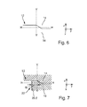
- FIG. 6 shows a front view of the intermediate image plane 26 of a simple Bifunktionslichtmoduls that not yet vertical high beam aperture, with the vertical V and the horizontal H of a screen illuminated by the light module.
- the x-direction and the z-direction satisfy the definition used above.
- the y-direction is parallel to a vehicle transverse axis. This should apply to all figures in this application.
- Above the here and also in the invention mirrored on both sides Abblertztblende 12 is the low beam volume. Below the diaphragm, of which only the diaphragm edge can be seen, lies the high beam volume. When only the high beam sources are turned on, only the high beam volume 16 is filled with light.
- the low beam distribution according to the FIG. 4 by the imaging properties of the secondary optics, which images the internal light distribution occurring in the intermediate image plane by permutation from above and below into the apron of the projection light module.
- FIG. 7 shows a front view of the intermediate image plane of a Bifunktionslichtmodul according to the invention, in comparison to that in the FIG. 6 shown light module additionally has a vertical high beam aperture 32, with the vertical V and the horizontal H of a light module illuminated by the screen. Above the here and also in the invention mirrored on both sides Abblertztblende is the low beam volume. Below the aperture, of which only the aperture edge is visible, is the high beam volume.
- the secondary optics facing vertical diaphragm edge is arranged in the horizontal y-direction at a lateral distance dy to the HV point and thus to the optical axis.
- the optical axis is perpendicular to the intermediate image plane and passes through the HV point.
- At least parts of the front edge of the additional vertical diaphragm 22 are preferably located in the focal plane of the projection lens.
- This focal plane is the intermediate image plane 26.
- These parts of the front edge of the diaphragm 22 are then mapped sharply as a cut-off in the front of the headlight traffic space.
- This vertical cut-off is for the right-hand side of the vehicle in a horizontal range of about -2 ° ... -10 °, so slightly to the left of the center, which is marked by the HV point.
- the brightness maximum of a high beam characteristic is usually in the HV point.
- the maximum brightness of the above-described Operafernlichtver activist whose vertical cut-off on the horizontal axis at -2 ° to -10 °, not directly to this vertical cut-off, but a few degrees next to it.
- the partial surface 22.2 of the vertical diaphragm 22 facing the optical axis of the projection light module is preferably at least partially mirrored and either flat or specially shaped to achieve an optical effect and the mirrored one Distribute luminous flux in a targeted manner.
- a preferred embodiment provides structuring (for example matting) of the foremost edge 22.1 of the vertical diaphragm, or of the lateral surface 22.2 of the vertical diaphragm adjoining directly to the front edge. This is in the FIG. 8 shown schematically.
- structuring which replaces the reflective coating in a narrow range whose width is preferably less than 2 mm, a scattering effect and thus the desired smooth course of the brightness is achieved right and left of the cut-off line.
- a further embodiment is characterized in that the side directed toward the optical axis of the module of a vertical aperture running obliquely to the optical axis has a plurality of facets or reflector segments. It is also preferable that these facets or reflector segments have different reflection properties.
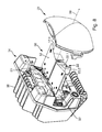
- FIG. 8 shows an isometric perspective view of a complex light source 34, a diaphragm assembly 36 and a secondary optics of an embodiment of a light module according to the invention.
- the complex light source here has a heat sink, a plurality of semiconductor light sources and primary optics 24, 32, which are combined to form a structural unit.
- the dashed line represents an optical axis 38 of the light module.
- the view is from the front and from the top.
- the primary optics 24, 32 which are realized here as refractive and in addition with internal total reflections working transparent solid, one sees essentially the light exit surfaces.
- the semiconductor light sources are hidden here by the primary optics.
- one semiconductor light source each interacts with a respective primary optics, so that each primary optic light is collimated by exactly one semiconductor light source and light from in each case one semiconductor light source is fed into only one primary optic.
- the composite diaphragm 36 has a Abblertztblende 12 with a Abbleriumtblendenkante 12.1, which extends substantially horizontally and in the region of the optical axis has a demarcated by two creases stage with which the known asymmetry of the low beam distribution is generated.
- the in the Fig. 8 visible surface of the diaphragm 12 is preferably mirrored.
- a part of the semiconductor light sources is arranged together with the respectively associated primary optics in the low beam volume so that the light is concentrated in a region at the diaphragm edge, whereby the inner light distribution is produced in the intermediate image plane, which is projected by the secondary optics as a low beam distribution.
- a further part of the semiconductor light sources, together with the respectively associated primary optics, are arranged in the high-beam volume located under the diaphragm so that their light is concentrated in an area at the diaphragm edge, whereby the inner light distribution produced by the secondary optics as the high-beam distribution or in the intermediate image plane Sub-beam distribution is projected, depending on which light sources are turned on.
- These light sources are also referred to below as high beam sources.
- On the vertical aperture 22 is in the description of the FIG. 9 received.
- FIG. 9 shows the subject of the FIG. 8 in a perspective view obliquely from the front and below and thus represents in particular the high beam volume.
- the composite diaphragm 36 in addition to its horizontal portion 12 vertical aperture 22, 23, which divide the high beam volume in the sub-volumes.
- Each of the vertical high beam apertures divides the high beam volume into the right for the above use the respective high-beam iris right high-beam volume and left of the respective high-beam iris left high beam volume, the diaphragm edge is arranged so that it is displayed by the secondary optics as more vertical than horizontal light-dark boundary in the outer light distribution.
- Another high-beam diaphragm 25 is arranged transversely to the optical axis 38. Although this high-beam diaphragm has an optically effective diaphragm edge 25.1, but due to its orientation, it has no effect on the beam path, which goes beyond a shading effect.
- the other two long-distance diaphragms 22, 13 do not extend transversely, but at an angle to the optical axis 38 of the light module, or at an angle to the identical optical axis 38 of the complex light source 34.
- Each of these two other high-beam diaphragms 22, 23 extending obliquely to the optical axis 38 lies on top one page the optical axis 38 and does not cross the optical axis 38 thereby.
- the two oblique light apertures 22, 23 extending obliquely to the optical axis lie on different sides of the optical axis 38, so that one is on the right and the other on the left of the optical axis 38.
- the respective partial high beam bundle each facing side of an oblique to the optical axis extending high-beam aperture 22, 23 is preferably mirrored.
- the diaphragm surface is preferably structured in a scattering manner, for example matted.
- the width of the scattered structured region is preferably less than 2 mm, in particular less than 1 mm. This is in the FIG. 8 shown.
- FIGS. 10 to 16 show Figures 10 . 12 and 14 each beam paths of an embodiment of a complex light source of an embodiment of a projection light module according to the invention, and the Figures 11 . 13 . 15 and 16 show each resulting Part high beam distributions.
- the in the Figures 10 . 12 and 14 perspective used is similar to the perspective of the FIG. 9 and shows a complex light source each substantially from below.
- the in the Figures 10 . 12 and 14 Embodiments shown differ from the embodiment described in the FIGS. 8 and 9 are represented by two features.
- a first difference is that the aperture edges of the vertical beam hoods in the subject of the Figures 10 . 12 and 14 not in the same area as the diaphragm edge of the low-beam lens hood. Under the preferably fulfilled condition that the diaphragm edge 12.1 of the low-beam diaphragm lies in the focal surface of the secondary optics, this results in a defocused arrangement of the vertical diaphragm edges. Therefore, these diaphragm edges are not sharply imaged, so that in this embodiment a less steep gradient of the brightness gradient over the cut-off line results than in the case of a sharp image.
- a complex light source 34 with a central light bundle 40 which is generated by a combination of a central light source and a central primary optics and by a first vertical diaphragm edge 25.1 and a second vertical diaphragm edge 22.1 is bounded on the right and left.
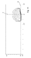
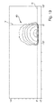
- FIG. 11 shows a resultant high-beam distribution 41 produced by projection from this beam, bounded on the right and on the left by a sharp, vertical cut-off line.
- the right light-dark border in the FIG. 11 results here as an image of the right diaphragm edge 25.1 from the FIG. 10 because the secondary optics 26 up and down and right and left reversed and the figure represents a view from below.
- the divisional light distribution produced by the central light bundle is preferably 10 ° to 15 ° wide in the horizontal and, apart from an asymmetry generated by the diaphragm edge of the low-beam light distribution, symmetrical to an average vertical, which preferably passes through the HV point.
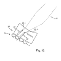
- FIG. 12 shows in detail a complex light source 34 with an adjacent to the central light beam and / or the central light beam 40 overlapping further light beam 42, which is generated by a composite of a arranged next to the central light source further light source and fed by this further light source further primary optics and by the second vertical diaphragm edge 22.1 and a third vertical diaphragm edge 23.1 is bounded on the right and left.
- FIG. 12 shows a resultant high-beam distribution 43 produced by projection from this beam, bounded on the right and on the left by a sharp, vertical cut-off line.
- the right light-dark border in the FIG. 13 results as an image of the right diaphragm edge 22.1 from the FIG. 12 because the secondary optics up and down and right and left reversed.
- the one of the Further light beam 42 generated Ambifernlichtverander is in the horizontal preferably 10 ° to 15 ° wide and apart from a generated by the diaphragm edge of the Abbleriumtver notorious asymmetry symmetrical to a mean vertical, which is offset relative to the HV point preferably by half the width of the Operafernlichtver notorious.
- an overlap of the further partial high-beam distribution and the central light distribution is achieved, in which the overlap region is approximately half as wide as one of the two preferably approximately equally wide partial high-beam light distributions.
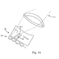
- FIG. 14 shows in detail a complex light source 34 with an adjacent to the further light beam and / or the further light beam 43 overlapping outer light bundle 44, generated by a composite of an additional light source arranged outside the outer light source and fed with this outer light source primary optics and right through a third vertical diaphragm edge 23.1 is limited.
- the light beam is not limited in this embodiment.
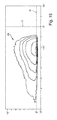
- FIG. 15 shows a resultant high-beam distribution 45 produced by projection from this beam 44, bounded on the right by a sharp, vertical cut-off and its brightness becoming gradually softer to the left.
- the right light-dark border in the FIG. 15 results as an image of the right diaphragm edge 23.1 from the FIG. 14 because the secondary optics up and down and right and left reversed.
- the partial high-light distribution 45 generated by the outer light bundle 44 is preferably 30 ° to 45 ° wide in the horizontal. Your right light-dark border is preferably located in the center of the adjacent further partial long-distance light distribution 43.
- the FIG. 16 shows a high beam distribution 47 (but without low beam component) of a projection light module on a mounting side (left here), as it results when all the high beam light sources of the projection light module are turned on. A full high beam distribution results from this by connecting the low beam distribution.
- the brightness in the area of the main beam distribution illuminated by the respective light beam can be reduced in order to prevent or at least reduce dazzling of other road users located in this area , This is preferably done automatically controlled by evaluation of a camera image (eg the image of an infrared camera), which is known as such.
- a camera image eg the image of an infrared camera
- projection light module has a rigid composite panel 36 with a continuous horizontal mirror aperture 12 and at least two rigidly connected both with each other and with the horizontal mirror aperture vertical aperture 22, 23.
- a plurality of individually switchable light sources which are preferably semiconductor light sources and whose light bundles 40, 42, 44 are each formed and / or directed by an optical attachment, radiate above (for the low beam) and below (for the high beam) the aperture 12 and to the right and / or to the left of the vertical apertures 22, 23, 25 in the direction of the projection lens / secondary optics with a concentration zone near the diaphragm edge 12. 1 of the horizontal diaphragm 12.
- At least two of the vertical diaphragms extend obliquely toward the optical axis, viewed from the light sources, and are always located on one side of the optical axis in the case of a projection light module. In the case of the projection light module set up for the other installation side, the panels are located on the other side.
- the at least two vertical and obliquely tapered to the optical axis aperture 22, 23 terminate in a configuration as shown in the Figures 10 . 12 and 14 is shown, with a clear distance (greater than 10 mm) to the front, the secondary optics facing edge 12.1 of the horizontal aperture 12 so that their front edges 22.1, 23.1 are shown slightly out of focus and thus the individual Operafernlichtbündel homogeneous with simultaneous activation of their light sources together overlap.
- Unwanted scattered light beam paths are shaded in a preferred embodiment by stray light apertures 25, which are preferably arranged transversely to the optical axis.
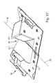
- FIG. 17 shows an embodiment of a composite diaphragm, which is set up in combination with the other components of a projection light module described here to produce a low beam and a Clfernlichtverander with only one vertical diaphragm edge 22.1.
- a projection light module which has a rigid composite panel 36 with a continuous horizontal mirror panel 12 and at least one rigid panel 22 rigidly connected thereto.
- a plurality of individually switchable light sources which are preferably semiconductor light sources and whose light bundles are each reshaped and / or directed by an optical attachment, radiate above and below the light source horizontal aperture 12 and here to the left of the vertical aperture 22 in the direction of the projection lens with a concentration zone near the aperture edge 12.1 of the horizontal aperture.
- the vertical diaphragm 22 having a vertical diaphragm edge 22.1 extends obliquely toward the optical axis 38, viewed from the light sources, and ends preferably in the region of the diaphragm bending point of the horizontal diaphragm 12 so that its front, optically effective diaphragm edge 22. Dark border is mapped.
- a scattered light aperture 25 extending transversely to the optical axis 38 serves here for shadowing unwanted scattered light beam paths.
- a vertical aperture edge of the lens hood lies here in an extension of the vertical aperture and thus provides a shadow line that coincides with the shadow line of the vertical aperture edge 22.1.
- FIG. 18 shows an intermediate image plane of another embodiment from the front, so from a direction of radiation opposite viewing direction.
- This embodiment is characterized in that it has two in the high beam volume below the horizontal aperture extending chambers or high beam subvolumes 50, 52 has.
- a central chamber 50 in which passes the HV point piercing optical axis 38, serves to generate a marking spot. This is followed on the right by a partial remote light chamber 52.
- the chambers 50, 52 are bounded by vertical apertures 54, 56, which are similar to the apertures 22, 23 configured and together with the horizontal aperture 12 form a rigid composite aperture.
- the sides of the diaphragms facing the light beam be it the horizontal diaphragm 12 or the vertical diaphragms 54, 56, are each mirrored, it also being possible here to use scattering structuring, as described above with reference to FIGS FIG. 8 have been explained. This also applies to all embodiments shown in this application.
- FIG. 19 shows an intermediate image plane of another embodiment.
- This refinement is characterized in that it has three chambers 53, 50, 52 extending in the high-beam volume below the horizontal diaphragm 12.
- a central chamber 50 serves to generate a marking spot.
- This is followed on the right and left by a Operafernlichthunt 53, 52 at.
- all three chambers are independently switchable in the high beam range.
- the marking function can be met with the recognized in connection with a per se known infrared night vision function, for example, a pedestrian and marked, that is, can be lit separately.
- a horizontal rotation of the projection light module as it is already widespread as such by curve light modules in the market, ensures the correct orientation of the strip on the pedestrian. But it can also be a Detailfernlicht right or Activate left or joint simultaneously right and left.
- the lighting performance of the projection light module increases decisively, because then both headlights in certain driving situations right and left, for example, at the same time.
- the high beam range can be activated.
- FIG. 20 shows an intermediate image plane of another embodiment.
- This embodiment is characterized in that it has a plurality in the high beam volume below the horizontal aperture 12 extending chambers 60 which are each separated by a vertical high beam aperture 59, 61 from each other, which are preferably designed as the aperture 22, 23.
- the high beam distribution is divided into a plurality of vertical stripes, which then result in a segmented stripline.
Landscapes
- Engineering & Computer Science (AREA)
- General Engineering & Computer Science (AREA)
- Physics & Mathematics (AREA)
- Microelectronics & Electronic Packaging (AREA)
- Optics & Photonics (AREA)
- Mechanical Engineering (AREA)
- Non-Portable Lighting Devices Or Systems Thereof (AREA)
Applications Claiming Priority (1)
| Application Number | Priority Date | Filing Date | Title |
|---|---|---|---|
| DE102014215785.4A DE102014215785B4 (de) | 2014-08-08 | 2014-08-08 | Projektionslichtmodul für einen Kraftfahrzeugscheinwerfer |
Publications (1)
| Publication Number | Publication Date |
|---|---|
| EP2982902A1 true EP2982902A1 (fr) | 2016-02-10 |
Family
ID=53716323
Family Applications (1)
| Application Number | Title | Priority Date | Filing Date |
|---|---|---|---|
| EP15176376.0A Withdrawn EP2982902A1 (fr) | 2014-08-08 | 2015-07-13 | Module lumineux de projection pour un phare de vehicule automobile |
Country Status (4)
| Country | Link |
|---|---|
| US (1) | US10071674B2 (fr) |
| EP (1) | EP2982902A1 (fr) |
| CN (1) | CN105371215B (fr) |
| DE (1) | DE102014215785B4 (fr) |
Cited By (4)
| Publication number | Priority date | Publication date | Assignee | Title |
|---|---|---|---|---|
| FR3062457A1 (fr) * | 2017-02-01 | 2018-08-03 | Valeo Vision | Module d'eclairage d'un faisceau lumineux pour projecteur de vehicule automobile |
| EP3502553A1 (fr) * | 2017-12-21 | 2019-06-26 | Valeo Vision | Dispositif d'éclairage de véhicule automobile |
| EP3839327A1 (fr) * | 2019-12-20 | 2021-06-23 | ZKW Group GmbH | Module de projection pour un phare de véhicule automobile |
| WO2023054525A1 (fr) | 2021-10-01 | 2023-04-06 | 株式会社小糸製作所 | Phare de véhicule |
Families Citing this family (10)
| Publication number | Priority date | Publication date | Assignee | Title |
|---|---|---|---|---|
| FR3037125B1 (fr) * | 2015-06-08 | 2019-10-11 | Valeo Vision | Dissipateur thermique pour module d'emission lumineuse, module d'emission lumineuse et dispositif lumineux associes |
| CN106764792A (zh) * | 2016-11-30 | 2017-05-31 | 马瑞利汽车零部件(芜湖)有限公司 | 整合雾灯功能的汽车前照灯系统 |
| KR101916723B1 (ko) * | 2016-12-27 | 2018-11-08 | 엘지전자 주식회사 | 차량용 램프 및 그것의 제어방법 |
| DE102016125887A1 (de) * | 2016-12-29 | 2018-07-05 | Automotive Lighting Reutlingen Gmbh | Lichtmodul für Kraftfahrzeugscheinwerfer |
| DE102017110876A1 (de) * | 2017-05-18 | 2018-11-22 | Automotive Lighting Reutlingen Gmbh | Lichtmodul eines Kraftfahrzeugscheinwerfers und Kraftfahrzeugscheinwerfer mit einem solchen Lichtmodul |
| DE102018111038A1 (de) * | 2018-05-08 | 2019-11-14 | Automotive Lighting Reutlingen Gmbh | Bifunktions-Projektionslichtmodul, Kraftfahrzeugscheinwerfer mit einem solchen Modul und Kraftfahrzeugbeleuchtungseinrichtung mit zwei solcher Scheinwerfer |
| DE102019108232A1 (de) * | 2019-03-29 | 2020-10-01 | Automotive Lighting Reutlingen Gmbh | Teilfernlichtmodul für einen Kraftfahrzeugscheinwerfer |
| CN110056828A (zh) * | 2019-06-04 | 2019-07-26 | 海纳川海拉(三河)车灯有限公司 | 一种汽车自适应远光灯系统 |
| KR20210082632A (ko) * | 2019-12-26 | 2021-07-06 | 에스엘 주식회사 | 차량용 램프 |
| FR3125860B1 (fr) | 2021-07-30 | 2023-08-04 | Valeo Vision | Module d’eclairage bi-led avec piece optique transparente mince |
Citations (10)
| Publication number | Priority date | Publication date | Assignee | Title |
|---|---|---|---|---|
| US20080239742A1 (en) * | 2007-03-26 | 2008-10-02 | Koito Manufacturing Co., Ltd. | Lamp unit of vehicle headlamp |
| EP2101107A2 (fr) * | 2008-03-12 | 2009-09-16 | Koito Manufacturing Co., Ltd | Appareil de phare de véhicule |
| JP2010118274A (ja) * | 2008-11-13 | 2010-05-27 | Koito Mfg Co Ltd | 車両用前照灯 |
| DE102009008631A1 (de) | 2009-02-12 | 2010-08-19 | Automotive Lighting Reutlingen Gmbh | Projektionsmodul für einen Kraftfahrzeugscheinwerfer |
| EP2336634A1 (fr) * | 2009-12-16 | 2011-06-22 | Koito Manufacturing Co., Ltd. | Phare de véhicule |
| JP2011146172A (ja) * | 2010-01-12 | 2011-07-28 | Koito Mfg Co Ltd | 車両用前照灯 |
| DE102010046021A1 (de) * | 2010-09-18 | 2012-03-22 | Automotive Lighting Reutlingen Gmbh | Kraftfahrzeugscheinwerfer mit einem Mehrfunktions-Projektionsmodul |
| DE102011012742A1 (de) | 2010-12-21 | 2012-06-21 | Daimler Ag | Projektionsmodul für einen Fahrzeugscheinwerfer und Fahrzeugscheinwerfer |
| DE102011013211A1 (de) * | 2011-03-05 | 2012-09-06 | Automotive Lighting Reutlingen Gmbh | Kraftfahrzeugscheinwerfer mit einem Mehrfunktions-Projektionsmodul |
| JP2012186010A (ja) * | 2011-03-04 | 2012-09-27 | Koito Mfg Co Ltd | 車両用前照灯 |
-
2014
- 2014-08-08 DE DE102014215785.4A patent/DE102014215785B4/de active Active
-
2015
- 2015-07-13 EP EP15176376.0A patent/EP2982902A1/fr not_active Withdrawn
- 2015-08-06 US US14/820,161 patent/US10071674B2/en active Active
- 2015-08-07 CN CN201510484625.4A patent/CN105371215B/zh not_active Expired - Fee Related
Patent Citations (10)
| Publication number | Priority date | Publication date | Assignee | Title |
|---|---|---|---|---|
| US20080239742A1 (en) * | 2007-03-26 | 2008-10-02 | Koito Manufacturing Co., Ltd. | Lamp unit of vehicle headlamp |
| EP2101107A2 (fr) * | 2008-03-12 | 2009-09-16 | Koito Manufacturing Co., Ltd | Appareil de phare de véhicule |
| JP2010118274A (ja) * | 2008-11-13 | 2010-05-27 | Koito Mfg Co Ltd | 車両用前照灯 |
| DE102009008631A1 (de) | 2009-02-12 | 2010-08-19 | Automotive Lighting Reutlingen Gmbh | Projektionsmodul für einen Kraftfahrzeugscheinwerfer |
| EP2336634A1 (fr) * | 2009-12-16 | 2011-06-22 | Koito Manufacturing Co., Ltd. | Phare de véhicule |
| JP2011146172A (ja) * | 2010-01-12 | 2011-07-28 | Koito Mfg Co Ltd | 車両用前照灯 |
| DE102010046021A1 (de) * | 2010-09-18 | 2012-03-22 | Automotive Lighting Reutlingen Gmbh | Kraftfahrzeugscheinwerfer mit einem Mehrfunktions-Projektionsmodul |
| DE102011012742A1 (de) | 2010-12-21 | 2012-06-21 | Daimler Ag | Projektionsmodul für einen Fahrzeugscheinwerfer und Fahrzeugscheinwerfer |
| JP2012186010A (ja) * | 2011-03-04 | 2012-09-27 | Koito Mfg Co Ltd | 車両用前照灯 |
| DE102011013211A1 (de) * | 2011-03-05 | 2012-09-06 | Automotive Lighting Reutlingen Gmbh | Kraftfahrzeugscheinwerfer mit einem Mehrfunktions-Projektionsmodul |
Cited By (10)
| Publication number | Priority date | Publication date | Assignee | Title |
|---|---|---|---|---|
| FR3062457A1 (fr) * | 2017-02-01 | 2018-08-03 | Valeo Vision | Module d'eclairage d'un faisceau lumineux pour projecteur de vehicule automobile |
| EP3357752A1 (fr) * | 2017-02-01 | 2018-08-08 | Valeo Vision | Module d'éclairage d'un faisceau lumineux pour projecteur de véhicule automobile |
| US10267477B2 (en) | 2017-02-01 | 2019-04-23 | Valeo Vision | Light beam lighting module for motor vehicle headlight |
| EP3502553A1 (fr) * | 2017-12-21 | 2019-06-26 | Valeo Vision | Dispositif d'éclairage de véhicule automobile |
| FR3075926A1 (fr) * | 2017-12-21 | 2019-06-28 | Valeo Vision | Dispositif d’eclairage de vehicule automobile |
| US10697602B2 (en) | 2017-12-21 | 2020-06-30 | Valeo Vision | Motor vehicle lighting device |
| EP3839327A1 (fr) * | 2019-12-20 | 2021-06-23 | ZKW Group GmbH | Module de projection pour un phare de véhicule automobile |
| WO2021121817A1 (fr) * | 2019-12-20 | 2021-06-24 | Zkw Group Gmbh | Module de projection d'un phare de véhicule automobile |
| WO2023054525A1 (fr) | 2021-10-01 | 2023-04-06 | 株式会社小糸製作所 | Phare de véhicule |
| US12449105B2 (en) | 2021-10-01 | 2025-10-21 | Koito Manufacturing Co., Ltd. | Vehicle headlight |
Also Published As
| Publication number | Publication date |
|---|---|
| DE102014215785A1 (de) | 2016-02-11 |
| CN105371215B (zh) | 2018-06-15 |
| US20160039330A1 (en) | 2016-02-11 |
| DE102014215785B4 (de) | 2016-03-31 |
| CN105371215A (zh) | 2016-03-02 |
| US10071674B2 (en) | 2018-09-11 |
Similar Documents
| Publication | Publication Date | Title |
|---|---|---|
| DE102014215785B4 (de) | Projektionslichtmodul für einen Kraftfahrzeugscheinwerfer | |
| EP2518397B1 (fr) | Phare de véhicule avec un module de base et un module spot pour produire un faisceau de route et système de phare correspondant | |
| EP3351849B1 (fr) | Module à led et dispositif d'éclairage pour un véhicule automobile pourvu d'une pluralité de tels modules à led | |
| EP2420728B1 (fr) | Phare avec gradient d'intensité lumineuse ciblée amortie sur la limite de clair-obscur | |
| EP2523022B1 (fr) | Module d'éclairage pour un phare de véhicule automobile destiné à la production d'une distribution lumineuse variable et phare de véhicule automobile doté d'un tel module d'éclairage | |
| DE102014200368B4 (de) | Teilfernlicht-Projektionslichtmodul für einen Kraftfahrzeugscheinwerfer | |
| DE19961942C5 (de) | Scheinwerferanlage für Fahrzeuge zur Erzeugung von Lichtbündeln mit unterschiedlicher Charakteristik | |
| DE102011078653B4 (de) | Vorsatzoptik zur Bündelung von ausgesandtem Licht mindestens einer Halbleiterlichtquelle | |
| EP2799761A2 (fr) | Module d'éclairage de phare de véhicule automobile | |
| DE102009008631A1 (de) | Projektionsmodul für einen Kraftfahrzeugscheinwerfer | |
| DE102005014754A1 (de) | KFZ-Scheinwerfer | |
| WO2012119976A1 (fr) | Projecteur de véhicule automobile équipé d'un module de projection multifonction | |
| EP1792118A1 (fr) | Systeme optique pour un phare de vehicule automobile, unite d'eclairage pour un phare de vehicule automobile et phare de vehicule automobile | |
| DE102014205994A1 (de) | Lichtmodul mit Halbleiterlichtquelle und Vorsatzoptik und Kraftfahrzeugscheinwerfer mit einem solchen Lichtmodul | |
| DE102009022848B4 (de) | Scheinwerferanordnung und Scheinwerfersystem für ein Kraftfahrzeug | |
| EP2730836B1 (fr) | Module d'éclairage pour un phare de véhicule automobile | |
| DE202010018337U1 (de) | Optische Vorrichtung für Kraftfahrzeug | |
| DE202009019171U1 (de) | Optisches Modul für ein Kraftfahrzeug, das selektiv einen Bereich beleuchten kann | |
| EP3301350A1 (fr) | Module d'éclairage pour phare de véhicule automobile | |
| EP2402647B1 (fr) | Module d'éclairage pour un phare de véhicule automobile | |
| DE102013202370B4 (de) | Lichtmodul für ein Kraftfahrzeug | |
| DE102018111038A1 (de) | Bifunktions-Projektionslichtmodul, Kraftfahrzeugscheinwerfer mit einem solchen Modul und Kraftfahrzeugbeleuchtungseinrichtung mit zwei solcher Scheinwerfer | |
| DE102019118590A1 (de) | Lichtmodul eines Kraftfahrzeugscheinwerfers und Kraftfahrzeugscheinwerfer mit einem solchen Lichtmodul |
Legal Events
| Date | Code | Title | Description |
|---|---|---|---|
| PUAI | Public reference made under article 153(3) epc to a published international application that has entered the european phase |
Free format text: ORIGINAL CODE: 0009012 |
|
| AK | Designated contracting states |
Kind code of ref document: A1 Designated state(s): AL AT BE BG CH CY CZ DE DK EE ES FI FR GB GR HR HU IE IS IT LI LT LU LV MC MK MT NL NO PL PT RO RS SE SI SK SM TR |
|
| AX | Request for extension of the european patent |
Extension state: BA ME |
|
| 17P | Request for examination filed |
Effective date: 20160809 |
|
| RBV | Designated contracting states (corrected) |
Designated state(s): AL AT BE BG CH CY CZ DE DK EE ES FI FR GB GR HR HU IE IS IT LI LT LU LV MC MK MT NL NO PL PT RO RS SE SI SK SM TR |
|
| RIN1 | Information on inventor provided before grant (corrected) |
Inventor name: HUMBURG, JENS Inventor name: STAUSS, BENJAMIN Inventor name: HOSSFELD, WOLFGANG Inventor name: ROSENHAHN, ERNST-OLAF |
|
| STAA | Information on the status of an ep patent application or granted ep patent |
Free format text: STATUS: EXAMINATION IS IN PROGRESS |
|
| 17Q | First examination report despatched |
Effective date: 20210217 |
|
| RIN1 | Information on inventor provided before grant (corrected) |
Inventor name: ROSENHAHN, ERNST-OLAF Inventor name: HOSSFELD, WOLFGANG Inventor name: HUMBURG, JENS Inventor name: STAUSS, BENJAMIN |
|
| REG | Reference to a national code |
Ref country code: DE Ref legal event code: R079 Free format text: PREVIOUS MAIN CLASS: F21S0008100000 Ipc: F21S0041147000 |
|
| RIC1 | Information provided on ipc code assigned before grant |
Ipc: F21S 41/663 20180101ALI20230202BHEP Ipc: F21S 41/43 20180101ALI20230202BHEP Ipc: F21S 41/365 20180101ALI20230202BHEP Ipc: F21S 41/32 20180101ALI20230202BHEP Ipc: F21S 41/147 20180101AFI20230202BHEP |
|
| GRAP | Despatch of communication of intention to grant a patent |
Free format text: ORIGINAL CODE: EPIDOSNIGR1 |
|
| STAA | Information on the status of an ep patent application or granted ep patent |
Free format text: STATUS: GRANT OF PATENT IS INTENDED |
|
| INTG | Intention to grant announced |
Effective date: 20230314 |
|
| STAA | Information on the status of an ep patent application or granted ep patent |
Free format text: STATUS: THE APPLICATION IS DEEMED TO BE WITHDRAWN |
|
| 18D | Application deemed to be withdrawn |
Effective date: 20230725 |