EP2101421A2 - Datenweiterleitungsvorrichtung, Kommunikationsvorrichtung und Datenweiterleitungsverfahren - Google Patents
Datenweiterleitungsvorrichtung, Kommunikationsvorrichtung und Datenweiterleitungsverfahren Download PDFInfo
- Publication number
- EP2101421A2 EP2101421A2 EP09155148A EP09155148A EP2101421A2 EP 2101421 A2 EP2101421 A2 EP 2101421A2 EP 09155148 A EP09155148 A EP 09155148A EP 09155148 A EP09155148 A EP 09155148A EP 2101421 A2 EP2101421 A2 EP 2101421A2
- Authority
- EP
- European Patent Office
- Prior art keywords
- symbol
- data
- communication apparatus
- symbol string
- relaying
- Prior art date
- Legal status (The legal status is an assumption and is not a legal conclusion. Google has not performed a legal analysis and makes no representation as to the accuracy of the status listed.)
- Granted
Links
Images




Classifications
-
- H—ELECTRICITY
- H04—ELECTRIC COMMUNICATION TECHNIQUE
- H04B—TRANSMISSION
- H04B7/00—Radio transmission systems, i.e. using radiation field
- H04B7/14—Relay systems
-
- H—ELECTRICITY
- H04—ELECTRIC COMMUNICATION TECHNIQUE
- H04B—TRANSMISSION
- H04B7/00—Radio transmission systems, i.e. using radiation field
- H04B7/14—Relay systems
- H04B7/15—Active relay systems
- H04B7/155—Ground-based stations
- H04B7/15521—Ground-based stations combining by calculations packets received from different stations before transmitting the combined packets as part of network coding
-
- H—ELECTRICITY
- H04—ELECTRIC COMMUNICATION TECHNIQUE
- H04L—TRANSMISSION OF DIGITAL INFORMATION, e.g. TELEGRAPHIC COMMUNICATION
- H04L12/00—Data switching networks
- H04L12/28—Data switching networks characterised by path configuration, e.g. LAN [Local Area Networks] or WAN [Wide Area Networks]
-
- H—ELECTRICITY
- H04—ELECTRIC COMMUNICATION TECHNIQUE
- H04W—WIRELESS COMMUNICATION NETWORKS
- H04W88/00—Devices specially adapted for wireless communication networks, e.g. terminals, base stations or access point devices
- H04W88/02—Terminal devices
- H04W88/04—Terminal devices adapted for relaying to or from another terminal or user
-
- H—ELECTRICITY
- H04—ELECTRIC COMMUNICATION TECHNIQUE
- H04W—WIRELESS COMMUNICATION NETWORKS
- H04W88/00—Devices specially adapted for wireless communication networks, e.g. terminals, base stations or access point devices
- H04W88/02—Terminal devices
- H04W88/06—Terminal devices adapted for operation in multiple networks or having at least two operational modes, e.g. multi-mode terminals
Definitions
- Certain aspects of the present invention discussed herein are related to a data relaying apparatus, a data relaying method, and a communication apparatus which receives relayed data.
- the simplest method for transmitting data between communication apparatuses is directly transmitting data from one communication apparatus to another communication apparatus.
- this method uses large transmission power to guarantee quality of the wireless communication, for example, when wireless communication is performed between a BS (base station) and a MS (mobile station), a result of which is the power consumption increasing.
- BS base station
- MS mobile station
- the size of a wireless cell may be reduced.
- the number of base stations BS will increase and ultimately increase the system construction cost.
- relay stations are provided between communication apparatuses.
- a description will be given for a relaying method employed when a relay station (RS) is provided between a BS and a MS and two-hop transmission is carried out between the base station (BS) and the mobile station (MS).
- RS relay station
- MS mobile station
- Fig. 11A is a diagram illustrating an example of a relaying method.
- This relaying method uses the following four phases to bidirectionally transmit data between the BS and the MS. More specifically, in the first phase (P-1), the BS transmits a signal conveying data to the RS. In the second phase (P-2), the RS transmits the signal to the MS. In the third phase (P-3), the MS transmits a signal conveying data to the RS. In the fourth phase (P-4), the RS transmits the signal to the BS. In this relaying method, four communication resources having orthogonal relation are employed.
- This relaying method is a kind of "DF (Decode-and-Forward) relaying", requiring four phases.
- Fig. 11B is a diagram illustrating an example of a relaying method.
- This relaying method requires the following three phases to bidirectionally transmit signals between the BS and the MS. More specifically, in the first phase (P-1), the BS transmits a signal S1 to the RS via a link D1. In the second phase (P-2), the MS transmits a signal S2 to the RS via a link D2. In the third phase (P-3), the RS decodes the signals S1 and S2, calculates an exclusive OR (XOR) of each respective pair of bits of decoded data to combine them. After that the RS generates symbols corresponding to a modulation method based on the combined data and multicasts the calculated results to the BS and the MS.
- This relaying method is a kind of "DF (Decode-and-Forward) relaying" but requiring three phases.
- Fig. 12 illustrates a configuration of a network coding section for combining pieces of information received by the RS via a plurality of communication lines and for transmitting the combined result.
- this network coding section includes an XOR unit 1, a header adding unit 2, a CRC (Cyclic Redundancy Check) unit 3, an FEC (Forward Error Correction) unit 4, and a modulating unit 5 (see, for example, R. Ahlswede, N. Cai, S.Y.R. Li and R.W. Yeung, "Network information flow", IEEE Transactions on Information Theory, Vol.46, No.4, pp1204-1216, July 2000 ).
- the XOR unit 1 calculates an XOR of each respective pair of bits of pieces of decoded data, namely, a pair of bit strings, to generate multicast data.
- the header adding unit 2 adds a header to the output of the XOR unit 1.
- the CRC unit 3 adds a CRC bit, for error detection at the receiving side, to the output of the header adding unit 2.
- the FEC unit 4 performs error correcting coding, such as a turbo encoding, on the output of the CRC unit 3.
- the modulating unit 5 modulates a symbol corresponding to a modulation method based on the output of the FEC unit 4.
- the RS performs the XOR calculation on each respective pair of bits (bit by bit calculation) to generate multicast data.
- the BS can acquire data transmitted from the MS by performing an XOR calculation of the multicast data and the data that the BS has transmitted to the RS.
- the MS can acquire data transmitted from the BS by performing an XOR calculation of the multicast data and the data that the MS has transmitted to the RS.
- bidirectional communication may be realized.
- the DF relaying is described in " Coded bi-directional relaying" written by P. Larsson, N. Johansson, K.E. Sunell, the 5th Scandinavian WS on Wireless Ad-Hoc Networks(AdHoc'05), Sweden, May 2005 .
- Fig. 11C is a diagram illustrating another relaying method according to the related art.
- signals are bidirectionally transmitted between the BS and the MS with the following two phases. More specifically, in the first phase, signal transmission from the BS to the RS and signal transmission from the MS to the RS are simultaneously carried out. In the second phase, the RS amplifies a signal (signal including interference of each other), which is a signal obtained by combining the signals having been simultaneously transmitted from the BS and the MS in a space, and multicasts the amplified signal to the BS and the MS. At this time, the RS does not decode the received signals for transmission.
- This relaying method is a kind of AF (Amplify-and-Forward) relaying.
- the AF relaying employs two orthogonal communication resources. Logically, throughput of the AF relaying may become equal to a double of the throughput of the relaying method illustrated in Fig. 11A at the maximum. Meanwhile, the AF relaying is described in " Wireless network coding by amplify-and-forward for bi-directional traffic flows" written by P. Popovsiki, and H. Yomo, IEEE Communications Letters, Vol.11, No.1, pp16-18, January 2007 .
- the relaying methods illustrated in Fig. 11A-11C have characteristics summarized in Fig. 13 . Since each phase is independently controlled in the relaying method, both of reliability of links and classical flexibility (degree-of-freedom) of communication are high. However, since the number of phases increases in this relaying method, the throughput reduces, as a result of which communication efficiency decreases.
- the flexibility of communication means a degree of freedom for selecting a data transmission modulation scheme and a code rate, i.e., modulation and coding scheme (MCS).
- pieces of data are received from two links. After two bit strings having the same number of bits resulting from decoding of the received pieces of data are combined by calculating an XOR for two bit strings (bit by bit) to generate one bit string, modulation is performed based on symbols having certain number of bits corresponding to a certain modulation method by dividing this bit string. Accordingly, one modulation scheme is selected at the time of multicast of the bit string D3 to the BS and the MS.
- the QPSK is selected for both the transmissions to satisfy transmission requirements of both the transmissions.
- the AF relaying explained above does not have the flexibility of communication. Additionally, since the noises are also amplified in the RS in an environment with many noises, communication performance significantly drops. Although introduction of, for example, a DNF (Denoise-and-Forward) relaying method reduces the seriousness of this problem, the introduction of the DNF relaying method also complicates a configuration of the RS.
- DNF Denoise-and-Forward
- a data relaying apparatus for relaying data bidirectionally transmitted between a first communication apparatus and a second communication apparatus, includes a first symbol string generator configured to generate, in accordance with a first modulation method, a first symbol string from first data transmitted from the second communication apparatus; a second symbol string generator configured to generate, in accordance with a second modulation method, a second symbol string from second data transmitted from the first communication apparatus; and a combining unit configured to combine a first symbol of the first symbol string and a second symbol of the second symbol string by calculating an exclusive OR on the first symbol and the second symbol to generate a third symbol string to be multicasted to the first communication apparatus and the second communication apparatus.
- a communication apparatus for receiving multicast data relayed by a data relaying apparatus with network coding includes a decoder configured to decode the multicast data, generated by the data relaying apparatus by calculating an exclusive OR for each respective pair of symbols, using transmission data transmitted to the data relaying apparatus from the communication apparatus to acquire reception data.
- a data relaying method for relaying data bidirectionally transmitted between a first communication apparatus and a second communication apparatus includes generating, in accordance to a first modulation method, a first symbol string from first data transmitted from the second communication apparatus; generating, in accordance with a second modulation method, a second symbol string from second data transmitted from the first communication apparatus; combining a first symbol of the first symbol string and a second symbol of the second symbol string by calculating an exclusive OR on the first symbol and the second symbol to generate a third symbol string; multicasting data based on the third symbol string to the first communication apparatus and the second communication apparatus; receiving the third symbol string multicasted by the data relaying apparatus by the first communication apparatus and the second communication apparatus; decoding the third symbol string received using the first data by the first communication apparatus; and decoding the third symbol string received using the second data by the second communication apparatus.
- Embodiments for carrying out a data relaying apparatus, a data relaying method, and a communication apparatus relating to the present invention are described with reference to the figures.
- a relaying apparatus generates symbol data corresponding to respective modulation methods for each of a plurality of received bit strings and combines the plurality of pieces of symbol data.
- symbol data can be generated for each of the plurality of bit strings.
- this configuration allows symbol data to be generated for each of the plurality of bit strings in accordance with different modulation methods (schemes).
- Fig. 1 is a configuration example of a network coding section of a relay station according to this embodiment.
- this network coding section includes header adding units 2a and 2b, CRC (Cyclic Redundancy Check) units 3a and 3b (error detection encoder), FEC (Forward Error Correction) units 4a and 4b (error correction encoder), symbol string generating units 6a and 6b (symbol string generator), an each-symbol XOR unit 7 (exclusive OR calculation unit), an MCS (Modulation and Coding Scheme) determining unit 8 (modulation and coding method determining unit), and a modulating unit 9 (modulator).
- CRC Cyclic Redundancy Check
- FEC Forward Error Correction
- symbol string generating units 6a and 6b symbol string generator
- an each-symbol XOR unit 7 exclusive OR calculation unit
- MCS Modulation and Coding Scheme
- the header adding units 2a and 2b add headers to bit strings B1 and B2, which have been transmitted from a mobile station and a base station and demodulated by the relay station, respectively.
- the CRC units 3a and 3b add CRC bits to the outputs of the header adding units 2a and 2b, respectively, for error detection at the receiving side.
- the FEC units 4a and 4b perform error correction encoding, such as a turbo encoding. FEC bits may be added to the outputs of the CRC units 3a and 3b, respectively, for error correction at the receiving side.
- the symbol string generating units (symbol string generator) 6a and 6b generate symbol strings from the bit strings output from the FEC units 4a and 4b, respectively, on the basis of modulation method and/or coding method of a link between the relay station and the base station and a link between the relay station and the mobile station determined by the MCS determining unit 8.
- the each-symbol XOR unit 7 performs an XOR operation on each respective pair of symbols of the symbol strings generated by the symbol string generating units 6a and 6b to generate a multicast symbol.
- a symbol S1 generated by the symbol string generating unit 6a has M0 bits
- a symbol S2 generated by the symbol string generating unit 6b has M1 bits.
- the symbols S1 and S2 are represented as ⁇ 0,0 , ⁇ 0,1 , ..., ⁇ 0,M0-1 ⁇ and ⁇ 1,0 , ⁇ 1,1 , ..., ⁇ 1,M1-1 ⁇ , respectively.
- the multicast symbol ⁇ 0 , ⁇ 1 , ..., ⁇ M-1 ⁇ is mapped to a constellation diagram (signal constellation diagram) whose modulation order equals to log 2 max(M0, M1).
- Figs. 2 and 3 illustrate examples of XOR calculations performed by the each-symbol XOR unit 7 for each respective pair of symbols. More specifically, Fig. 2 illustrates an XOR operation between two 16QAM symbols, whereas Fig. 3 illustrates an XOR operation between a QPSK symbol and a 16QAM symbol. Since the bit lengths of the two symbols are the same in Fig. 2 , an XOR calculation is performed on each respective pair of bits of the two symbols. That is, the first (second, third, fourth) bit of the 16QAM symbol of S1 and the first (second, third, fourth) bit of the 16QAM symbol of S2 are used for XOR calculation. Since the bit lengths of the two symbols differ in Fig.
- XOR operations are performed on first two respective pairs of bits of the two symbols and the remaining two bits of the longer symbol are used as they are.
- the first (second) bit of the QPSK symbol of S1 and the first (second) bit of the 16QAM symbol of S2 are used for XOR calculation, and the third and fourth bit of the 16QAM symbol of S2 are not used for XOR calculation.
- the each-symbol XOR unit 7 performs an XOR operation for each symbol pair to generate a multicast symbol in this manner, whereby a disadvantage of the DF relaying that communication quality is restricted by data transmission of a link having unpreferable communication quality can be overcome. Additionally, the modulation order of the multicast symbol may be adjusted to the higher modulation order of two symbols.
- each-symbol XOR unit 7 performs the XOR calculation from MSB (Most Significant Bit), thereby guaranteeing the higher quality for the symbol having the lower modulation order.
- MSB Mobile Bit
- the LSB bits or other bits may also be used for XOR calculation instead of the MSB.
- the MCS determining unit 8 determines a MCS (Modulation and Coding Scheme) based on spectrum efficiencies of a link between a relay station and a base station (hereinafter, referred to as "a relay station-base station link”) and a link between the relay station and a mobile station (hereinafter, referred to as "a relay station-mobile station link"). More specifically, the MCS determining unit 8 determines the modulation and coding scheme in the following manner.
- MCS Modulation and Coding Scheme
- the spectrum efficiency of the relay station-base station link and the spectrum efficiency of the relay station-mobile station link are represented as C(BS)k1,k2( ⁇ BS) and C(MS)k1,k3( ⁇ MS), which are functions of SINR (Signal-to-Interference plus Noise power Ratio) ⁇ BS and ⁇ MS of the links, respectively.
- k1 and k2 are transmission and reception modulation orders, respectively
- k1 ⁇ k2, k1 ⁇ k3, and k1, k2, K3 ⁇ 2, 4, 6 ⁇ .
- overlapping is caused in design of an MCS table. More specifically, MCSs having different modulation orders and code rates for an identical SINR are provided.
- Figs. 14 and 15 illustrate cases with and without overlapping, respectively.
- the MCS determining unit 8 determines the modulation and coding scheme by performing global search of k1, k2, and k3 regarding a case with overlapping shown in Fig. 15 using Equation (2).
- the modulation and coding scheme When the modulation and coding scheme is determined, it is preferable to generally set the modulation order of both of the relay station-base station link and the relay station-mobile station link to the same value regardless of the code rate if possible. However, when the SINR is low, the performance may decrease in response to switching of the QPSK into the higher-order QAM because of constellation noises of the higher-order QAM.
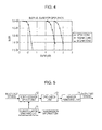
- Fig. 4 is a diagram illustrating a block error rate (BLER) of QPSK modulation of a code rate 1/2 against a symbol-to-noise ratio (Es/N0).
- the noise is the AWGN (Additive White Gaussian Noise).
- Fig. 4 illustrates data transmission cases of ordinal QPSK constellation, 16QAM constellation modulated with the QPSK symbol, and 64QAM constellation modulated with the QPSK symbol.
- repeated coding or trellis code modulation may be performed. More specifically, when different constellations are combined, a lower-order constellation is converted into a higher-order constellation by performing the repeated coding or the trellis code modulation. For example, a 16QAM symbol is obtained by repeating two bits of a QPSK symbol once and a 64QAM symbol is obtained by repeating two bits of the QPSK symbol twice.
- the modulating unit (modulator) 9 modulates a multicast symbol in accordance with the modulation and coding scheme determined by the MCS determining unit 8.
- a network decoding section for decoding multicast symbols Both of the base station and the mobile station include a network decoding section.
- Fig. 5 is a configuration example of a network decoding section. As shown in the drawing, the network decoding section includes a constellation swapping unit 11, a soft-decision de-FEC unit 12, a CRC check unit 13, and a header removing unit 14.
- the constellation swapping unit 11 swaps the constellation on the basis of transmission information. More specifically, the constellation swapping unit 11 swaps the constellation in the following manner.
- a 0 a 1 ... a M-1 is set as one of constellation points used by the relay station for multicasting and is referred to as a mother constellation.
- a constellation point of a new symbol which is formed based on transmission symbol S2 of the base station and used for demodulating multicast symbol, is set to a 0 , 0 a 0,1 ... a 0,M-1 .
- a constellation point of a new symbol which is formed based on transmission symbols S1 of the mobile station and used for demodulating multicast symbol, is set to a 1,0 a 1,1 ... a 1,M-1 .
- the symbol S1 includes transmission bits of ⁇ 0,0 , ⁇ 0,1 , ..., ⁇ 0,M0-1 ⁇
- the symbol S2 includes transmission bits of ⁇ 1,0 , ⁇ 1,1 , ..., ⁇ 1,M1-1 ⁇ .
- M max (M0, M1).
- the constellation points a 0,0 a 0,1 ... a 0,M-1 and a 1,0 a 1,1 ... a 1,M-1 are determined by Equation (3).
- a n , m ⁇ a m ⁇ XOR ⁇ ⁇ n + 1 ⁇ mod 2
- m m 0 , 1 , ⁇ , min M ⁇ 0 , M ⁇ 1 - 1
- a m m min M ⁇ 0 , M ⁇ 1 , ⁇ , M n - 1
- Equation (3) indicates that the new constellation point is based on the mother constellation and the transmission information. More specifically, the constellation swapping unit 11 swaps the constellation using the mother constellation and the transmission information.
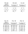
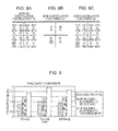
- Figs. 6A-8C are examples of constellation swapping.
- Figs. 6A-6C illustrate a case where both symbols are QPSK symbols.
- the symbol S1 is "01”
- the symbol S2 is "10”.
- Figs. 6A, 6B, and 6C illustrate a mother constellation, a new constellation for the symbol S1, and a new constellation for the symbol S2, respectively.
- the relay station determines an XOR of the symbol S1 "01" and the symbol S2 "10" to generate a multicast symbol "11".
- the base station updates the constellation using the mother constellation and the symbol S2, namely "10", to generate a new constellation point "01". More specifically, the symbol S1 is mapped to the same position as that of the multicast symbol.
- the symbol S2 is mapped to the same position as that of the multicast symbol in the mobile station. Accordingly, the base station and the mobile station can readily decode the multicast symbol using the new constellations shown in Figs. 6B and 6C , respectively.
- Figs. 7A-7C illustrate a case where both symbols are 16QAM symbols.
- the symbol S1 is "0110”
- the symbol S2 is "1011”. Accordingly, the multicast symbol is "1101”.
- Figs. 7A, 7B, and 7C illustrate a mother constellation, a new constellation for the symbol S1, and a new constellation for the symbol S2, respectively.
- Figs. 8A-8C illustrate a case where the symbol S1 is a QPSK symbol and the symbol S2 is a 16QAM symbol.
- the symbol S1 is "01”
- the symbol S2 is "1011”.
- the multicast symbol is "1111”.
- Figs. 8A, 8B, and 8C illustrate a mother constellation, a new constellation for the symbol S1, and a new constellation for the symbol S2, respectively.
- the soft-decision de-FEC unit (error correction decoder) 12 decodes the multicast symbol using the constellation swapped by the constellation swapping unit 11 and performs error detection/correction using the FEC.
- This soft-decision de-FEC unit 12 decodes the multicast symbol using soft decision.
- the CRC check unit 13 performs CRC check on a bit string having undergone the FEC-employing error detection/correction.
- the header removing unit 14 removes a header from the bit string having undergone the CRC check.
- the constellation swapping unit 11 swaps the constellation using the mother constellation and the transmission information in this manner, whereby the network decoding section can readily decode the multicast symbol.
- Fig. 9 illustrates comparison results of simulated throughput.
- Fig. 9 illustrates that throughput improves in the DF relaying method according to this embodiment in comparison with the DF relaying method according to the related art, namely, a method for performing an XOR operation for each bit to generate multicast data.
- the throughput improvement ratio is 39% in this simulation.
- Fig. 10 is a table showing a comparison of a relaying method according to this embodiment and relaying methods according to the related art. As illustrated in the table, flexibility of communication and throughput may be improved in the relaying method according to this embodiment in comparison with the DF relaying method according to the
- the symbol string generating units 6a and 6b of the relay station generate symbol strings on the basis of modulation and coding schemes of the relay station-base station link and the relay station-mobile station link, respectively.
- the each-symbol XOR unit 7 performs an XOR operation on each symbol pair of the symbol strings generated by the symbol string generating units 6a and 6b to generate a multicast symbol.
- the constellation swapping unit 11 swaps a constellation using a mother constellation and transmission information.
- the soft-decision de-FEC unit 12 then decodes a multicast symbol using the swapped constellation. Accordingly, it is possible to readily decode the multicast symbol.
- Network coding using an XOR operation for each symbol may improve the flexibility of communication without complicating conventional network coding and decoding.
- the present invention is not limited to these modulation and coding schemes.
- the present embodiment may be applied similarly to a case of using other modulation and coding schemes, such as 32QAM and 64QAM, for example.
- the flexibility of communication can be improved.
- application of elements, expressions, and given combinations of the elements of the invention to a method, an apparatus, a system, a computer program, a recording medium, and a data structure is also effective to achieve the above-described desirable outcomes and advantages.
- the invention also provides a computer program or a computer program product for carrying out any of the methods described herein, and a computer readable medium having stored thereon a program for carrying out any of the methods described herein.
- a computer program embodying the invention may be stored on a computer-readable medium, or it could, for example, be in the form of a signal such as a downloadable data signal provided from an Internet website, or it could be in any other form.
Landscapes
- Engineering & Computer Science (AREA)
- Computer Networks & Wireless Communication (AREA)
- Signal Processing (AREA)
- Mobile Radio Communication Systems (AREA)
- Radio Relay Systems (AREA)
- Digital Transmission Methods That Use Modulated Carrier Waves (AREA)
- Detection And Prevention Of Errors In Transmission (AREA)
Applications Claiming Priority (1)
| Application Number | Priority Date | Filing Date | Title |
|---|---|---|---|
| JP2008066786A JP5035045B2 (ja) | 2008-03-14 | 2008-03-14 | データ中継装置、通信装置およびデータ中継方法 |
Publications (3)
| Publication Number | Publication Date |
|---|---|
| EP2101421A2 true EP2101421A2 (de) | 2009-09-16 |
| EP2101421A3 EP2101421A3 (de) | 2009-10-21 |
| EP2101421B1 EP2101421B1 (de) | 2014-08-13 |
Family
ID=40886394
Family Applications (1)
| Application Number | Title | Priority Date | Filing Date |
|---|---|---|---|
| EP09155148.1A Ceased EP2101421B1 (de) | 2008-03-14 | 2009-03-13 | Datenweiterleitungsvorrichtung, Kommunikationsvorrichtung und Datenweiterleitungsverfahren |
Country Status (5)
| Country | Link |
|---|---|
| US (1) | US8270333B2 (de) |
| EP (1) | EP2101421B1 (de) |
| JP (1) | JP5035045B2 (de) |
| KR (1) | KR101050923B1 (de) |
| CN (1) | CN101534146B (de) |
Cited By (3)
| Publication number | Priority date | Publication date | Assignee | Title |
|---|---|---|---|---|
| EP2216954A1 (de) * | 2009-02-10 | 2010-08-11 | Fujitsu Limited | Datenrelaisvorrichtung, Kommunikationsvorrichtung und Kommunikationsverfahren |
| CN102299893A (zh) * | 2011-09-29 | 2011-12-28 | 中国人民解放军理工大学 | 具有频偏的双向ofdm系统的联合信道网络编码方法 |
| WO2012166619A1 (en) * | 2011-05-27 | 2012-12-06 | Qualcomm Incorporated | Transmission schemes for relay |
Families Citing this family (16)
| Publication number | Priority date | Publication date | Assignee | Title |
|---|---|---|---|---|
| JP5665850B2 (ja) * | 2009-04-27 | 2015-02-04 | アルカテル−ルーセント | データパケット中継およびデータパケット復号のための方法および装置 |
| EP2293466B1 (de) * | 2009-09-03 | 2013-08-28 | Mitsubishi Electric R&D Centre Europe B.V. | Verfahren und Vorrichtung zum Weiterschalten von Symbolen, die durch eine Quelle zu einem Ziel übertragen wurden |
| JPWO2011043230A1 (ja) * | 2009-10-07 | 2013-03-04 | 日本電信電話株式会社 | 無線通信システム、無線中継局装置、無線端末局装置、及び無線通信方法 |
| CN102111234B (zh) * | 2009-12-28 | 2014-10-22 | 上海无线通信研究中心 | 有效减小误码扩散的中继非选择性译码转发系统及方法 |
| US9124423B2 (en) * | 2010-05-14 | 2015-09-01 | International Business Machines Corporation | Iterative data secret-sharing transformation |
| JP5740590B2 (ja) * | 2010-12-03 | 2015-06-24 | 株式会社国際電気通信基礎技術研究所 | 無線装置およびそれを備えた無線通信システム |
| US8553792B2 (en) * | 2011-01-14 | 2013-10-08 | Mitsubishi Electric Research Laboratories, Inc. | Non-coherent space-time trellis-coded modulations for network-coded wireless relay communications |
| CN103516660B (zh) * | 2012-06-26 | 2016-12-21 | 华为技术有限公司 | 一种信号处理的方法、设备及系统 |
| JP5775105B2 (ja) * | 2013-03-04 | 2015-09-09 | 日本電信電話株式会社 | 受動光通信網における送信装置/方法及び受信装置/方法 |
| FR3015814A1 (fr) * | 2013-12-20 | 2015-06-26 | Orange | Procede de transmission d'un signal numerique pour un systeme marc a un relais half-duplex dynamique, produit programme et dispositif relais correspondants |
| FR3015815A1 (fr) | 2013-12-20 | 2015-06-26 | Orange | Procede de transmission d'un signal numerique pour un systeme marc a plusieurs relais half-duplex dynamiques,produit programme et dispositif relais correspondants |
| US9800311B2 (en) * | 2014-12-30 | 2017-10-24 | Electronics And Telecommunications Research Institute | Beam formation for data transmission for two-way multi-antenna relay system with physical network coding |
| US20170078014A1 (en) * | 2015-09-15 | 2017-03-16 | King Fahd University Of Petroleum And Minerals | Bandwidth efficient cooperative two-way amplify-and- forward relaying method |
| JP7048931B2 (ja) * | 2017-03-08 | 2022-04-06 | 株式会社国際電気通信基礎技術研究所 | 無線中継装置および無線中継方法 |
| JP6877708B2 (ja) * | 2017-03-09 | 2021-05-26 | 株式会社国際電気通信基礎技術研究所 | 無線中継装置および無線中継方法 |
| US12526070B1 (en) | 2023-12-19 | 2026-01-13 | Rockwell Collins, Inc. | Low latency digital rebroadcast of signals with FEC and interleaving |
Citations (1)
| Publication number | Priority date | Publication date | Assignee | Title |
|---|---|---|---|---|
| JP2008066786A (ja) | 2006-09-04 | 2008-03-21 | Sharp Corp | 画像処理装置 |
Family Cites Families (8)
| Publication number | Priority date | Publication date | Assignee | Title |
|---|---|---|---|---|
| US6101523A (en) * | 1998-05-19 | 2000-08-08 | United Microelectronics Corp. | Method and apparatus for controlling calculation error |
| EP1128623A1 (de) * | 2000-02-24 | 2001-08-29 | Alcatel | Verfahren zur Minimizierung der Sendeleistung von nicht-aktiven ATM Zellen in einem XDSL System mit trelliskodierter Modulation |
| DE60113128T2 (de) * | 2001-11-16 | 2006-03-02 | Matsushita Electric Industrial Co., Ltd., Kadoma | Hybrides ARQ Verfahren zur Datenpaketübertragung |
| KR100754660B1 (ko) * | 2004-06-19 | 2007-09-03 | 삼성전자주식회사 | 통신 시스템에서 적응 변조/부호 부 채널 할당 시스템 및 방법 |
| US7617269B2 (en) * | 2004-08-03 | 2009-11-10 | Stmicroelectronics Pvt. Ltd. | Logic entity with two outputs for efficient adder and other macro implementations |
| SE0403218D0 (sv) * | 2004-12-30 | 2004-12-30 | Ericsson Telefon Ab L M | Method and apparatus relating to communication- |
| KR100733117B1 (ko) | 2006-04-03 | 2007-06-28 | 엘에스전선 주식회사 | 고속전력선통신을 위한 광 가입자 단말 장치 및 광 신호분배 방법 |
| US8040836B2 (en) * | 2006-05-26 | 2011-10-18 | Microsoft Corporation | Local network coding for wireless networks |
-
2008
- 2008-03-14 JP JP2008066786A patent/JP5035045B2/ja not_active Expired - Fee Related
-
2009
- 2009-03-10 KR KR1020090020343A patent/KR101050923B1/ko not_active Expired - Fee Related
- 2009-03-10 US US12/400,894 patent/US8270333B2/en not_active Expired - Fee Related
- 2009-03-13 EP EP09155148.1A patent/EP2101421B1/de not_active Ceased
- 2009-03-13 CN CN2009100081953A patent/CN101534146B/zh not_active Expired - Fee Related
Patent Citations (1)
| Publication number | Priority date | Publication date | Assignee | Title |
|---|---|---|---|---|
| JP2008066786A (ja) | 2006-09-04 | 2008-03-21 | Sharp Corp | 画像処理装置 |
Non-Patent Citations (3)
| Title |
|---|
| P. LARSSON; N. JOHANSSON; K.E. SUNELL: "Coded bi-directional relaying", 5TH SCANDINAVIAN WS ON WIRELESS AD-HOC NETWORKS(ADHOC'05), May 2005 (2005-05-01) |
| P. POPOVSIKI; H. YOMO: "Wireless network coding by amplify-and-forward for bi-directional traffic flows", IEEE COMMUNICATIONS LETTERS, vol. 11, no. 1, January 2007 (2007-01-01), pages L6 - 18 |
| R. AHLSWEDE ET AL.: "Network information flow", IEEE TRANSACTIONS ON INFORMATION THEORY, vol. 46, no. 4, July 2000 (2000-07-01), pages 1204 - 1216 |
Cited By (4)
| Publication number | Priority date | Publication date | Assignee | Title |
|---|---|---|---|---|
| EP2216954A1 (de) * | 2009-02-10 | 2010-08-11 | Fujitsu Limited | Datenrelaisvorrichtung, Kommunikationsvorrichtung und Kommunikationsverfahren |
| WO2012166619A1 (en) * | 2011-05-27 | 2012-12-06 | Qualcomm Incorporated | Transmission schemes for relay |
| CN102299893A (zh) * | 2011-09-29 | 2011-12-28 | 中国人民解放军理工大学 | 具有频偏的双向ofdm系统的联合信道网络编码方法 |
| CN102299893B (zh) * | 2011-09-29 | 2013-12-18 | 中国人民解放军理工大学 | 具有频偏的双向ofdm系统的联合信道网络编码方法 |
Also Published As
| Publication number | Publication date |
|---|---|
| US20090232043A1 (en) | 2009-09-17 |
| KR20090098696A (ko) | 2009-09-17 |
| EP2101421A3 (de) | 2009-10-21 |
| CN101534146A (zh) | 2009-09-16 |
| KR101050923B1 (ko) | 2011-07-20 |
| JP5035045B2 (ja) | 2012-09-26 |
| JP2009225063A (ja) | 2009-10-01 |
| US8270333B2 (en) | 2012-09-18 |
| EP2101421B1 (de) | 2014-08-13 |
| CN101534146B (zh) | 2013-01-30 |
Similar Documents
| Publication | Publication Date | Title |
|---|---|---|
| EP2101421B1 (de) | Datenweiterleitungsvorrichtung, Kommunikationsvorrichtung und Datenweiterleitungsverfahren | |
| JP4915450B2 (ja) | ネットワーク符号化方法およびネットワーク符号化装置 | |
| US9425885B2 (en) | Network coded data communication | |
| JP4709227B2 (ja) | 無線通信システムにおける双方向中継のための方法及び装置 | |
| US20110014865A1 (en) | Cooperative reception diversity apparatus and method based on signal point rearrangement or superposition modulation in relay system | |
| Di Renzo | On the achievable diversity of repetition-based and relay selection network-coded cooperation | |
| US20080026693A1 (en) | Multihop Radio Network System | |
| Zou et al. | An opportunistic cooperation scheme and its BER analysis | |
| Xiao et al. | Error performance analysis of signal superposition coded cooperative diversity. | |
| Chu et al. | Implementation of co-operative diversity using message-passing in wireless sensor networks | |
| Zhou et al. | A joint design of physical layer network coding and channel coding for wireless networks | |
| Benamira et al. | NCC wireless networks: reed-Solomon channel coding and outage probability | |
| Zheng et al. | Performance analysis of HARQ transmission in cooperative DF relaying systems | |
| JP5740590B2 (ja) | 無線装置およびそれを備えた無線通信システム | |
| Chu et al. | Fractional cooperation using coded demodulate-and-forward | |
| Pan et al. | Mapping codebook-based physical network coding for asymmetric two-way relay channels | |
| Abd Aziz et al. | On the Improvement of Maximum Likelihood Detection in Multiple Relay Systems | |
| Li et al. | General design criteria and properties of cooperative MTCM systems | |
| Nazer et al. | Compute-and-forward: Error-correcting codes for wireless network coding on the physical layer | |
| Feghhi et al. | Spectrally efficient cooperative coded schemes for next generation wireless networks | |
| Luo et al. | Error recovery with soft value combining for wireless cooperative systems | |
| Wu et al. | A system level performance study on symbol-wise XOR based bi-directional relaying | |
| Khan et al. | Cooperative Networks | |
| Duhamel | Semi-orthogonal MARC with half duplex relaying: A backward compatible cooperative network with interference channels | |
| Whang et al. | Cooperative Multiuser Relay Communication with Superposition Coding |
Legal Events
| Date | Code | Title | Description |
|---|---|---|---|
| PUAI | Public reference made under article 153(3) epc to a published international application that has entered the european phase |
Free format text: ORIGINAL CODE: 0009012 |
|
| AK | Designated contracting states |
Kind code of ref document: A2 Designated state(s): AT BE BG CH CY CZ DE DK EE ES FI FR GB GR HR HU IE IS IT LI LT LU LV MC MK MT NL NO PL PT RO SE SI SK TR |
|
| AX | Request for extension of the european patent |
Extension state: AL BA RS |
|
| PUAL | Search report despatched |
Free format text: ORIGINAL CODE: 0009013 |
|
| AK | Designated contracting states |
Kind code of ref document: A3 Designated state(s): AT BE BG CH CY CZ DE DK EE ES FI FR GB GR HR HU IE IS IT LI LT LU LV MC MK MT NL NO PL PT RO SE SI SK TR |
|
| AX | Request for extension of the european patent |
Extension state: AL BA RS |
|
| 17P | Request for examination filed |
Effective date: 20100329 |
|
| AKX | Designation fees paid |
Designated state(s): DE FR GB IT |
|
| GRAP | Despatch of communication of intention to grant a patent |
Free format text: ORIGINAL CODE: EPIDOSNIGR1 |
|
| INTG | Intention to grant announced |
Effective date: 20140306 |
|
| GRAS | Grant fee paid |
Free format text: ORIGINAL CODE: EPIDOSNIGR3 |
|
| GRAA | (expected) grant |
Free format text: ORIGINAL CODE: 0009210 |
|
| RIN1 | Information on inventor provided before grant (corrected) |
Inventor name: OBUCHI, KAZUHISA Inventor name: TANIGUCHI, TOMOHIKO Inventor name: WU, JIANMING |
|
| AK | Designated contracting states |
Kind code of ref document: B1 Designated state(s): DE FR GB IT |
|
| REG | Reference to a national code |
Ref country code: GB Ref legal event code: FG4D |
|
| REG | Reference to a national code |
Ref country code: DE Ref legal event code: R096 Ref document number: 602009025895 Country of ref document: DE Effective date: 20140918 |
|
| PG25 | Lapsed in a contracting state [announced via postgrant information from national office to epo] |
Ref country code: IT Free format text: LAPSE BECAUSE OF FAILURE TO SUBMIT A TRANSLATION OF THE DESCRIPTION OR TO PAY THE FEE WITHIN THE PRESCRIBED TIME-LIMIT Effective date: 20140813 |
|
| REG | Reference to a national code |
Ref country code: DE Ref legal event code: R097 Ref document number: 602009025895 Country of ref document: DE |
|
| PLBE | No opposition filed within time limit |
Free format text: ORIGINAL CODE: 0009261 |
|
| STAA | Information on the status of an ep patent application or granted ep patent |
Free format text: STATUS: NO OPPOSITION FILED WITHIN TIME LIMIT |
|
| 26N | No opposition filed |
Effective date: 20150515 |
|
| REG | Reference to a national code |
Ref country code: FR Ref legal event code: PLFP Year of fee payment: 8 |
|
| REG | Reference to a national code |
Ref country code: FR Ref legal event code: PLFP Year of fee payment: 9 |
|
| PGFP | Annual fee paid to national office [announced via postgrant information from national office to epo] |
Ref country code: DE Payment date: 20170307 Year of fee payment: 9 Ref country code: FR Payment date: 20170213 Year of fee payment: 9 |
|
| PGFP | Annual fee paid to national office [announced via postgrant information from national office to epo] |
Ref country code: GB Payment date: 20170308 Year of fee payment: 9 |
|
| REG | Reference to a national code |
Ref country code: DE Ref legal event code: R119 Ref document number: 602009025895 Country of ref document: DE |
|
| GBPC | Gb: european patent ceased through non-payment of renewal fee |
Effective date: 20180313 |
|
| PG25 | Lapsed in a contracting state [announced via postgrant information from national office to epo] |
Ref country code: DE Free format text: LAPSE BECAUSE OF NON-PAYMENT OF DUE FEES Effective date: 20181002 |
|
| PG25 | Lapsed in a contracting state [announced via postgrant information from national office to epo] |
Ref country code: GB Free format text: LAPSE BECAUSE OF NON-PAYMENT OF DUE FEES Effective date: 20180313 |
|
| PG25 | Lapsed in a contracting state [announced via postgrant information from national office to epo] |
Ref country code: FR Free format text: LAPSE BECAUSE OF NON-PAYMENT OF DUE FEES Effective date: 20180331 |