EP2102894B1 - Verfahren zum temperieren eines substrats - Google Patents
Verfahren zum temperieren eines substrats Download PDFInfo
- Publication number
- EP2102894B1 EP2102894B1 EP06840969.7A EP06840969A EP2102894B1 EP 2102894 B1 EP2102894 B1 EP 2102894B1 EP 06840969 A EP06840969 A EP 06840969A EP 2102894 B1 EP2102894 B1 EP 2102894B1
- Authority
- EP
- European Patent Office
- Prior art keywords
- substrate
- contact surface
- fluid
- fluid flow
- main body
- Prior art date
- Legal status (The legal status is an assumption and is not a legal conclusion. Google has not performed a legal analysis and makes no representation as to the accuracy of the status listed.)
- Active
Links
Images
Classifications
-
- H—ELECTRICITY
- H10—SEMICONDUCTOR DEVICES; ELECTRIC SOLID-STATE DEVICES NOT OTHERWISE PROVIDED FOR
- H10P—GENERIC PROCESSES OR APPARATUS FOR THE MANUFACTURE OR TREATMENT OF DEVICES COVERED BY CLASS H10
- H10P72/00—Handling or holding of wafers, substrates or devices during manufacture or treatment thereof
- H10P72/70—Handling or holding of wafers, substrates or devices during manufacture or treatment thereof for supporting or gripping
- H10P72/78—Handling or holding of wafers, substrates or devices during manufacture or treatment thereof for supporting or gripping using vacuum or suction, e.g. Bernoulli chucks
-
- H—ELECTRICITY
- H10—SEMICONDUCTOR DEVICES; ELECTRIC SOLID-STATE DEVICES NOT OTHERWISE PROVIDED FOR
- H10P—GENERIC PROCESSES OR APPARATUS FOR THE MANUFACTURE OR TREATMENT OF DEVICES COVERED BY CLASS H10
- H10P72/00—Handling or holding of wafers, substrates or devices during manufacture or treatment thereof
- H10P72/04—Apparatus for manufacture or treatment
- H10P72/0431—Apparatus for thermal treatment
- H10P72/0432—Apparatus for thermal treatment mainly by conduction
-
- H—ELECTRICITY
- H10—SEMICONDUCTOR DEVICES; ELECTRIC SOLID-STATE DEVICES NOT OTHERWISE PROVIDED FOR
- H10P—GENERIC PROCESSES OR APPARATUS FOR THE MANUFACTURE OR TREATMENT OF DEVICES COVERED BY CLASS H10
- H10P72/00—Handling or holding of wafers, substrates or devices during manufacture or treatment thereof
- H10P72/04—Apparatus for manufacture or treatment
- H10P72/0431—Apparatus for thermal treatment
- H10P72/0434—Apparatus for thermal treatment mainly by convection
Definitions
- the invention relates to a method for tempering a substrate and in particular for tempering a thin curved or curved wafer.
- holding devices and in particular wafer chucks are usually used, which usually have a planar bearing surface for the disk-shaped substrates.
- heating and / or cooling elements are formed in the substrate holding device, or the holding device is combined with a conventional thermochuck.
- the substrate In order to transfer the controlled temperature of the device also to the substrate, the substrate must be in good thermal contact with the support surface of the holding device.
- vacuum openings are often formed in the contact surface, in order to allow suction of the substrate. On the one hand, this improves the thermal contact between the substrate and the abutment surface and, on the other hand, prevents slippage of the substrate on the abutment surface.
- thermochucks with planar bearing surfaces are particularly well suited for planar disc-shaped substrates.
- very thin substrates and in particular wafers often have a pronounced curvature or deflection, which results from mechanical stresses in the substrate. Such bulges prevent planar application of the substrate to a flat abutment surface of a thermochuck.
- Such curved or curved substrates must first be pressed against the contact surface in order to produce a large-area contact between the substrate and the contact surface. Subsequently, the substrate can be held by suction in contact with the contact surface. Curved substrates thus require a special work step to allow tempering with a conventional thermochuck. The process of mechanical pressure of the substrate against the contact surface also leads to a mechanical stress on the substrate.
- DE 10 2005 014 513 A1 discloses an apparatus and method for tempering a substrate, and a method of making such a device, comprising: a first sub-element having a locating surface for abutment with the substrate and a first bonding surface; and a second sub-element, which has a second connection surface over which it bears at least partially against the first connection surface of the first sub-element, wherein at least one of the two sub-elements comprises ceramic material, at least one recess is provided in at least one of the two connection surfaces, the at least one cavity defined in the device, and at least one first connection opening is provided, via which a Temperierfluidzu- and / or outflow to and / or is made possible by the at least one cavity.
- EP 1 473 764 A2 discloses a multifunction substrate carrier and an associated docking station for realizing a detachable connection to a workpiece with a carrier substrate, a Bernoulli planarizer for planarizing the workpiece on the carrier substrate according to the Bernoulli principle, an electrostatic chuck for holding the workpiece on the carrier substrate by means of electrostatic Force and a vacuum Garvorrichtrung for holding the workpiece on the support substrate by means of vacuum force.
- the inventive method for tempering a substrate can be carried out with the aid of a device for tempering a substrate, in particular a wafer, comprising a tempered main body, comprising: a contact surface for abutment against the substrate, wherein in the contact surface at least one fluid outlet opening is formed; at least one fluid supply port, which is preferably disposed substantially outside the abutment surface; and at least one fluid flow channel formed in the tempered main body, which connects the fluid supply port to the at least one fluid outlet port, such that fluid supplied via the fluid supply port and exiting through the fluid outlet port between the abutment surface and the substrate has a fluid flow at least partially substantially parallel to the abutment surface generates that due to the reduction in the static pressure caused by the fluid movement in the fluid flow, a force is formed on the substrate with a force component directed substantially towards the contact surface.
- the static pressure in the fluid decreases as the flow rate of a fluid increases. This applies to both liquids and gases.
- a fluid surrounding the substrate in the remaining region is preferably essentially immobile, ie it preferably has no or at most a low flow velocity.
- the static pressure in the surrounding fluid is greater than in the flowing fluid between contact surface and substrate.
- the reduced static pressure between the substrate and the abutment surface causes a smaller compressive force on the surfaces of the substrate facing the abutment surface than the compressive force exerted by the substantially immobile or non-flowing fluid on the surfaces of the substrate not facing the abutment surface, in particular on the Contact surface facing away from surfaces of the substrate exercises.
- the difference in static pressure according to the known hydrodynamic paradox results in a resultant force on the substrate which acts substantially in the direction of the abutment surface.
- the present device for tempering a substrate and in particular a non-planar or curved or curved substrate is used, wherein at the fluid supply port, a fluid is supplied, which is passed through the formed in the main body fluid flow channel to the contact surface, where it exits through the fluid outlet opening again , The exiting fluid generates in the intermediate space between the contact surface and the substrate a fluid flow which has an at least partially substantially parallel to the contact surface component.
- the apparatus preferably comprises pressure supply means for providing a fluid pressure at the fluid supply port.
- the fluid supply connection is preferably arranged in a region outside the contact surface.
- a pressure generating means for example, a compressor could be provided, which is in communication with the fluid supply port.
- a fluid storage unit such as e.g. be provided for liquids particularly suitable higher-lying storage tank or a pressurized gas cylinder or pressure vessel.
- the pressure-providing device is designed to provide a fluid pressure that is above a static ambient pressure in the region of the substrate.
- the at least one fluid flow channel in the at least one fluid outlet opening formed in the contact surface preferably opens at an exit angle different from 0 ° to the direction perpendicular to the contact surface in the region of the at least one fluid outlet opening.
- the fluid enters one of the direction perpendicular to the contact surface direction deviates from the fluid outlet opening.
- a fluid flow arises directly at the outlet of the fluid from the fluid flow channel with a flow or flow component parallel to the contact surface.
- the exit angle ie the angle between the direction perpendicular to the contact surface and the direction in which the at least one fluid flow channel opens at the contact surface
- the at least one fluid flow channel extends at least in the area or in the vicinity of the mouth or contact surface substantially along an axis which forms an angle with the normal to the contact surface in a range of preferably more than 30 °, more preferably in is substantially in a range between 45 ° and 80 °, most preferably about 60 °.
- the fluid flow runs or flows in the mouth region of the fluid flow channel substantially along such an axis.
- the at least one fluid flow channel extends at least partially substantially along a straight axis. This reduces turbulence and thus friction losses in the fluid within the fluid flow channel.
- the at least one fluid flow channel in the region of the orifice runs along the contact surface essentially along a straight axis, which leads in particular to a reduction or avoidance of turbulence in the fluid flow forming between substrate and contact surface.
- the at least one fluid flow channel at least in regions substantially perpendicular to the flow direction of the fluid in the fluid flow channel has a cross-sectional area substantially in a range between 0.03 mm 2 and 3 mm 2 , preferably between 0.1 mm 2 and 0.5 mm 2 , most preferably about 0.2 mm 2 .
- the at least one fluid flow channel at least partially has a substantially constant cross-section. The avoidance of changes in the cross section of the fluid flow channel reduces turbulence and leads to a particularly laminar flow.
- the cross-sectional area of the at least one fluid outlet opening parallel to the abutment surface is substantially in a range between 0.05 mm 2 and 10 mm 2 , preferably between 0.2 mm 2 and 1 mm 2 , most preferably about 0.34 mm 2 .
- the at least one fluid flow channel is at least partially formed with a circular cross section whose diameter is substantially in a range between 0.2 mm and 2 mm, preferably between 0.4 mm and 0.8 mm, most preferably substantially at 0, 5 mm.
- a particularly laminar and low-turbulence flow can be formed in that the at least one fluid flow channel has a preferably substantially constant cross section, at least in the area of the orifice.
- the fluid flow channel is at least partially configured as a bore. It could be produced in a particularly simple manner as a bore, in particular in the region of the orifice in the contact surface, which impinges on the inside of the main body on a fluid pressure channel having a larger cross-sectional area.
- the at least one fluid flow channel is preferably connected via at least one fluid pressure channel to the fluid supply port, wherein the fluid pressure channel has a larger cross-sectional area than the fluid flow channel. Due to the larger cross-sectional area in the fluid pressure channel, friction losses during the supply of the fluid can be further reduced. In this case, the fluid in the fluid pressure channel has a low speed compared to the fluid flow channel.
- the fluid flow channel is formed as a bore which is not longer than 5 mm between fluid pressure channel and fluid outlet opening, most preferably not longer than 2 mm.
- the abutment surface of the device is substantially planar, that is, it is preferably substantially in one plane.
- planar or even substrates can thus be arranged very easily on the contact surface and tempered by means of the present device.
- the present device is also used for tempering thin curved or curved substrates.
- mechanical stresses in the material of the substrate often lead to a buckling of the slices or wafers.
- the disks or wafers can be bent by overcoming elastic forces again essentially in a plane.
- the present device is preferably used in particular for tempering such substrates, wherein the forces necessary for bending and thus arranging the bent substrates on the preferably planar contact surface are applied by a fluid flow formed between the contact surface and the curved substrate according to the principle described above become.
- a plurality of fluid flow channels are formed, which open into a plurality of fluid outlet openings.
- a particularly efficient distribution of the fluid flow over the entire contact surface can be effected.
- Each fluid flow which forms between the contact surface and the substrate and has a flow component parallel to the contact surface causes, in addition to a force on the substrate in the direction of the contact surface, a tangential force parallel to the contact surface or parallel to the surface of the substrate which faces the contact surface.
- These tangential or parallel forces are created by friction between fluid stream and substrate. If these tangential frictional forces are not distributed substantially symmetrically, this could lead to a resulting tangential total force and thus to a displacement of the substrate parallel to the contact surface and / or to a rotation of the substrate.
- the fluid outlet openings in the device are preferably at least partially substantially uniformly distributed substantially annularly about a central axis, each of the fluid flow channels extending to the respective at least one fluid outlet opening in a direction which lies in a plane with the central axis and pointing away from this.
- the fluid outlet openings are preferably arranged substantially in a circular ring about the central axis and thereby most preferably have substantially regular or even equal distances and / or angular intervals.
- each fluid flow channel in a plane in which also lies preferably substantially perpendicular to the contact surface central axis, causes the resulting fluid flow of emerging from the fluid outlet openings fluid only flow components in the axial direction, ie parallel to the central axis, and radial direction.
- advantageously tangential flow components are substantially avoided, which could lead to rotational forces on the substrate.
- the away from the central axis, ie outward orientation of the fluid flow channels also reduces the formation of a dynamic pressure, which could be on the substrate repellent, so directed away from the contact surface act. In an outward orientation, however, the fluid can flow freely to the side, so in the peripheral region of the space between the substrate and abutment surface.
- At least those fluid flow channels which open into the fluid outlet openings, which are arranged substantially in the same annulus about the central axis, have a magnitude substantially equal mouth angle and a substantially same cross-sectional area. Due to the uniform or regular arrangement of the fluid outlet openings in the annulus together with the substantially same mouth angles and the substantially same cross-sectional areas of the fluid flow channels, it is advantageously possible to form a substantially symmetrical distribution of the fluid flow. This can lead to the contact surface or to the substrate surface in Substantially parallel forces cancel each other, whereby a displacement force on the substrate is avoided parallel to the contact surface. Particularly preferably, the arrangement of the plurality of fluid flow channels on an axis and / or mirror symmetry.
- the at least one vacuum channel opens into at least one intake groove formed in the contact surface.
- This suction groove is arranged substantially helically about a central axis. But it could also be formed a plurality of Ansaugrillen, which are arranged substantially annular and concentric about a central axis.
- the device has a heating device, which is arranged on one of the contact surface substantially opposite side of the main body and electrically insulated from the main body by shielding.
- the heating device serves, in particular, for tempering the substrate via a corresponding temperature control of the main body.
- the heating device is an electrical or electronic heating device, such as a resistance heater.
- the Heating device is arranged on a substantially opposite to the contact surface side of the main body such that it is substantially electrically isolated from this.
- shielding means are advantageously provided which are arranged between the heating device and the main body.
- the main body has at least one sensor, which is electrically insulated from the main body by shielding means.
- the shielding means may be designed in particular according to the above embodiment.
- the sensor may advantageously be a temperature sensor. It is understood that the sensor may also perform any other function, such as measuring a voltage or current.
- the sensor may be formed separately from the main body. Preferably, however, the sensor is substantially embedded in the main body.
- the shielding means comprise at least two insulating layers, which are separated by a preferably grounded screen.
- the shield and insulating layers are particularly advantageously sandwiched. It is understood that also more than two insulation layers and / or more than one screen can be provided.
- the insulating layers are particularly advantageously formed from a material of high dielectric strength, such as Teflon or ceramic.
- the screen is particularly advantageously formed of a conductive material, such as stainless steel.
- step a) of providing a device for tempering a substrate a device is provided as described herein.
- step b) of the approach of the substrate to the abutment surface of the device the substrate is brought closer to the abutment surface in particular so that the forces acting on the substrate due to the fluid flow suffice to effect a further approximation or attraction of the substrate to the abutment surface ,
- the substrate is preferably approximated to a distance to the contact surface, which is smaller than about 20%, more preferably less than about 5% of the diameter or the lateral extent of the contact surface and / or the substrate.
- step b) of the approach of the substrate the substrate is already at least partially brought into mechanical contact with the contact surface.
- a curved or curved, in particular thin, substrate is tempered.
- the substrate is particularly preferably approximated in the step of approaching the contact surface with an at least partially substantially convex surface of the contact surface, that the at least partially substantially convex surface of the substrate faces the contact surface of the main body.
- the device provided in step a) has in the main body at least one vacuum channel which opens into at least one suction opening formed in the contact surface and is connected to a vacuum connection arranged outside the contact surface.
- the step d) of holding the substrate in thermal contact with the contact surface takes place by suction of the substrate via the at least one suction opening formed in the contact surface.
- the at least one vacuum channel can be formed either separately from the at least one fluid flow channel or as one and the same channel, which is used depending on the application as a fluid flow channel or as a vacuum channel.
- a switching valve is preferably provided, which connects the channel (fluid flow channel or vacuum channel) in particular depending on the valve position with the fluid supply port and / or with the vacuum port.
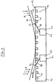
- Fig. 1 shows a cross section of a preferred embodiment of the device for controlling the temperature of a substrate (Thermochuck) and in particular a wafer.
- a main body 10 has a substantially planar abutment surface 12 in which a plurality of suction grooves 14 are formed. These suction grooves 14 are connected via not shown formed in the interior of the main body vacuum channels with at least one vacuum connection, also not shown. Via these suction grooves 14, a substrate 16 to be arranged on the abutment surface can be sucked towards the abutment surface and held against the abutment surface. For an effective suction process, however, the substrate 16 must already be approximated relatively close to the contact surface. In the in Fig.
- a thin, curved substrate 16 and in particular a thin wafer with a deflection should be tempered.
- This substrate 16 is approximated to the contact surface 12, wherein a convex surface of the substrate 16 faces the contact surface 12.
- the edge regions of the curved substrate 16 must first be brought into the vicinity of the contact surface 12, in order then to enable effective suction of the substrate 16 against the contact surface 12 via the suction grooves 14.
- fluid flow channels 18 as substantially rectilinear bores with a diameter of preferably formed about 0.6 mm, extending from compressed air channels 20 in the interior of the main body 10 to fluid outlet openings 22 in the contact surface 12.
- the fluid is conducted via the fluid flow channels 18 to the contact surface 12 and opens via the fluid outlet openings 22 into the space between the contact surface 12 and the substrate 16.
- the fluid preferably opens at an angle of about 60 ° to the normal direction of the contact surface.
- fluid flows 26 are formed substantially in extension from the directions of the fluid flow channels 18, which essentially have flow components parallel to the contact surface 12 or to the substrate 16.
- the device is thus designed to supply via the fluid supply port 24 a fluid, in particular a gas, into the fluid flow channel 18, which is preferably tubular in the interior of the main body 10 and directs the supplied fluid to the fluid outlet opening 22 in the contact surface 12.
- the fluid emerging from the fluid outlet opening 22 in the device forms a fluid flow 26 between the contact surface 12 and a substrate 16 located in the vicinity of the contact surface 12, which flow runs at least partially substantially parallel to the contact surface 12 and in the peripheral region of the contact surface 12 or . of the substrate 16 from the gap between contact surface 12 and substrate 16 exits.
- a relationship between the flow rate of a fluid and its static pressure means that with increasing flow velocity of a fluid, the static pressure in the fluid decreases. This relationship applies to both liquids and gases.
- the present device can thus be used with any fluids.
- the formation of a gas stream is just as conceivable as the formation of a liquid stream.
- Particularly preferred is the present device designed for use with compressed air. But it could also be used other gases such as nitrogen or noble gases.
- This effect causes in the present device, that decreases with increasing flow velocity of the fluid flow or the fluid flows 26 between the contact surface 12 and substrate 16 whose static pressure.
- the formation of the fluid stream 26 thus reduces the static pressure between the contact surface 12 and the substrate 16, while the static pressure of a fluid surrounding the substrate 16 in the remaining region is substantially not changes.
- the static pressure of the fluid in the area of the fluid streams 26 is markedly reduced compared to the environment in which the fluid has no flow or at least a significantly lower flow velocity.
- the resulting difference in static pressure above and below the substrate ie the difference of the compressive forces on the surface of the substrate facing the contact surface and the surface of the substrate facing away from the contact surface, causes an effective total force F on the substrate in the direction of the contact surface.
- This will be the in Fig. 1 shown bent substrate pressed in particular in the edge region in the direction of the contact surface or pulled and moved with sufficient elasticity of the substrate in the direction of the contact surface.
- the force F leads to a bending of the bent or curved substrate 16 or wafer and thus to a preferably planar or large-area, and particularly preferably substantially full-surface approach to the contact surface 12.
- the gap between the contact surface 12 and the substrate 16 decreases, whereby at constant fluid flow, the flow velocity in the fluid streams 26 increases, resulting in a further increase in the force acting on the substrate 16 force F.
- this effect has a self-reinforcing effect.
- the force F acting on the substrate 16 advantageously brings about at least partial adaptation of the shape of the substrate 16 to the contact surface 12
- thin bent wafers are brought by means of the forming force F in a planar shape and placed on a flat contact surface 12 of the present device, without the need for further mechanical means would be necessary to bend the substrate 16 in a plane.
- the substrate 16 After sufficient approximation of the substrate 16 to the contact surface 12 by the force F, the substrate can be maintained in the edge regions by suction via the suction grooves 14 on the contact surface 12.
- the fluid supply is interrupted by the fluid supply ports 24 again, so that no more fluid exits through the fluid outlet openings 22 in the space between the contact surface 12 and substrate 16.
- the substrate After the interruption of the fluid streams 26, the substrate is held in contact with the contact surface 12 and thus in good thermal contact with the main body 10 solely by suction or vacuum application by means of the suction grooves 14. By tempering the main body 10, the substrate 16 can thus be tempered easily and reliably.
- the vacuum channels and the fluid flow channels 18 are not formed as separate channels but the fluid flow channels 18 serve simultaneously as vacuum channels.
- the fluid flow channels preferably open into vacuum grooves.
- the fluid outlet openings are thus preferably formed in the vacuum grooves or as vacuum grooves.
- the substrate 16 in the vicinity of the contact surface 12th has been pulled or pressed, the fluid flow or the fluid flow is interrupted by the fluid flow channels 18 and generated in the fluid flow channels instead of a negative pressure or a vacuum.
- the substrate 16 is preferably further drawn or sucked to the contact surface 12, and held on the contact surface.
- the switching from the fluid flow to the vacuum is preferably carried out so fast that the substrate 16 is preferably not substantially or only slightly removed from the contact surface 12 during this.
- a switching valve is provided, by means of which the fluid flow channels 18 or vacuum channels can be connected depending on the valve position with a fluid pressure supply device or a vacuum supply device.
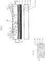
- Fig. 2 shows a cross section of another preferred embodiment of the device for controlling the temperature of a substrate (Thermochuck) and in particular a wafer.
- the main body 10 is arranged indirectly via shielding means 28 on a base plate 30.
- a heater 32 is provided such that it is also electrically isolated by the shielding means 28 of the main body 10.
- the heating device 32 serves, in particular, for controlling the temperature of the main body 10 and thus indirectly for controlling the temperature of the substrate 16.
- the shielding means 28 advantageously make it possible to apply the substrate 16 resting against the main body 10 or its contact surface 12 with a very high test voltage or current to operate or test.
- the main body 10 has at least one high-voltage and / or high-current connection 42, via which a voltage of up to approximately 8 kV can be supplied to the main body 10. But it can also be provided voltages up to about 10 kV.
- the shielding means 28 isolate the heater 32 from the main body 10th
- the shielding means 28 are particularly advantageously formed so that they are formed of two insulating layers 34 which are separated by a preferably grounded screen 36.
- the insulating layers 34 have advantageously a dielectric strength of about 10 kV.
- the device may additionally include a sensor 38 embedded in the main body 10.
- the sensor 38 may measure temperature, voltage, or current. It is understood that the sensor 38 may also detect other or alternative parameters. In order to protect the sensor 38 from a voltage applied to the main body 10 electrical voltage, this is also advantageously electrically insulated by shielding means 40 of the main body 10.
- the shielding means 40 have - as shown above - at least two insulating layers 34, which are separated by a preferably grounded screen 36.
Landscapes
- Container, Conveyance, Adherence, Positioning, Of Wafer (AREA)
Description
- Die Erfindung betrifft ein Verfahren zum Temperieren eines Substrats und insbesondere zum Temperieren eines dünnen gebogenen bzw. gewölbten Wafers.
- Zum Testen von Schaltungsanordnungen auf scheibenförmigen Substraten wie beispielsweise Halbleiterwafern, werden üblicherweise Haltevorrichtungen und insbesondere Waferchucks verwendet, die meist eine planare Auflagefläche für die scheibenförmigen Substrate aufweisen. Für eine Vielzahl von elektrischen Messungen zum Testen eines Substrats ist es notwendig, die Temperatur des Substrats auf einem konstanten, vorbestimmten Wert zu halten. Dazu werden in der Substrathaltevorrichtung Heiz- und/oder Kühlelemente ausgebildet oder die Haltevorrichtung wird mit einem herkömmlichen Thermochuck kombiniert. Um die geregelte Temperatur der Vorrichtung auch auf das Substrat zu übertragen, muß sich das Substrat in einem guten thermischen Kontakt mit der Auflagefläche der Haltevorrichtung befinden. In herkömmlichen Substrathaltevorrichtungen werden hierzu oft Vakuumöffnungen in der Anlagefläche ausgebildet, um damit ein Ansaugen des Substrats zu ermöglichen. Damit wird zum einen der thermische Kontakt zwischen Substrat und Anlagefläche verbessert, zum anderen wird dadurch ein Verrutschen des Substrats auf der Anlagefläche verhindert.
- Diese herkömmlichen Thermochucks mit planaren Auflageflächen sind insbesondere für planare scheibenförmige Substrate gut geeignet. Sehr dünne Substrate und insbesondere Wafer weisen allerdings oft eine stark ausgeprägte Wölbung bzw. Durchbiegung auf, die durch mechanische Spannungen im Substrat zustande kommt. Solche Wölbungen verhindern ein planares Anlegen des Substrats an einer ebenen Anlagefläche eines Thermochucks. In herkömmlichen Thermochucks müssen solche gebogenen bzw. gewölbten Substrate zunächst an die Anlagefläche gedrückt werden, um einen großflächigen Kontakt zwischen dem Substrat und der Anlagefläche herzustellen. Anschließend kann das Substrat durch Ansaugen in Kontakt mit der Anlagefläche gehalten werden. Gebogene Substrate erfordern somit einen besonderen Arbeitsschritt, um ein Temperieren mit einem herkömmlichen Thermochuck zu ermöglichen. Der Vorgang des mechanischen Andrückens des Substrats an die Anlagefläche führt außerdem zu einer mechanischen Belastung des Substrats.
-
DE 10 2005 014 513 A1 offenbart eine Vorrichtung und ein Verfahren zum Temperieren eines Substrats sowie ein Verfahren zur Herstellung einer solchen Vorrichtung, welche umfasst: ein erstes Teilelement, das eine Anlagefläche zum Anliegen an das Substrat sowie eine erste Verbindungsfläche aufweist; und ein zweites Teilelement, das eine zweite Verbindungsfläche aufweist, über die es zumindest teilweise an der ersten Verbindungsfläche des ersten Teilelements anliegt, wobei zumindest eines der beiden Teilelemente Keramikmaterial umfasst, zumindest in einer der beiden Verbindungsflächen zumindest eine Ausnehmung vorgesehen ist, die zumindest einen Hohlraum in der Vorrichtung definiert, und zumindest eine erste Anschlussöffnung vorgesehen ist, über die ein Temperierfluidzu- und/oder -abfluss zu und/oder von dem zumindest einen Hohlraum ermöglicht wird. -
EP 1 473 764 A2 offenbart einen Multifunktions-Substratträger sowie eine zugehörige Andockstation zur Realisierung einer lösbaren Verbindung zu einem Werkstück mit einem Trägersubstrat, einer Bernoulli-Planarisiervorrichtung zum Planarisieren des Werkstücks auf dem Trägersubstrat nach dem Bernoulli-Prinzip, einer elektrostatischen Haltevorrichtung zum Halten des Werkstücks auf dem Trägersubstrat mittels elektrostatischer Kraft und einer Vakuum-Haltevorrichtrung zum Halten des Werkstücks auf dem Trägersubstrat mittels Vakuumkraft. - Es ist eine Aufgabe der vorliegenden Erfindung, ein Verfahren zum Temperieren von Substraten und insbesondere von dünnen, gebogenen Substraten bereitzustellen, das eine einfache und für die Substrate schonende Handhabung ermöglicht.
- Die Aufgabe wird gelöst durch ein Verfahren zum Temperieren eines Substrats mit den in Anspruch 1 aufgeführten Merkmalen. Bevorzugte Ausführungsformen sind Gegenstand der abhängigen Ansprüche.
- Das erfindungsgemäße Verfahren zum Temperieren eines Substrats kann ausgeführt werden mit Hilfe einer Vorrichtung zum Temperieren eines Substrats, insbesondere eines Wafers, umfassend einen temperierten Hauptkörper, welcher aufweist: eine Anlagefläche zum Anliegen an das Substrat, wobei in der Anlagefläche zumindest eine Fluidaustrittsöffnung ausgebildet ist; zumindest einen Fluidzufuhranschluß, welcher vorzugsweise im wesentlichen außerhalb der Anlagefläche angeordnet ist; und zumindest einen in dem temperierten Hauptkörper ausgebildeten Fluidstromkanal, der den Fluidzufuhranschluß derart mit der zumindest einen Fluidaustrittsöffnung verbindet, dass ein über den Fluidzufuhranschluß zugeführtes und durch die Fluidaustrittsöffnung austretendes Fluid zwischen der Anlagefläche und dem Substrat einen zumindest teilweise im wesentlichen parallel zur Anlagefläche verlaufenden Fluidstrom derart erzeugt, dass sich durch die aufgrund der Fluidbewegung im Fluidstrom bewirkte Erniedrigung des statischen Drucks eine Kraft auf das Substrat mit einer im wesentlichen zur Anlagefläche hin gerichteten Kraftkomponente ausbildet.
- Gemäß einem Zusammenhang zwischen Strömungsgeschwindigkeit eines Fluids und dessen statischem Druck sinkt mit steigender Strömungsgeschwindigkeit eines Fluids der statische Druck in dem Fluid. Dies gilt sowohl für Flüssigkeiten als auch für Gase.
- Während im Zwischenraum zwischen dem Substrat und der Anlagefläche eine Fluidströmung auftritt, ist ein das Substrat im übrigen Bereich umgebendes Fluid vorzugsweise im wesentlichen unbewegt, d.h. es weist vorzugsweise gar keine oder höchstens eine geringe Strömungsgeschwindigkeit auf. Damit ist der statische Druck in dem umgebenden Fluid größer als im strömenden Fluid zwischen Anlagefläche und Substrat. Der erniedrigte statische Druck zwischen dem Substrat und der Anlagefläche bewirkt eine kleinere Druckkraft auf die der Anlagefläche zugewandten Flächen des Substrats als die Druckkraft, die das im wesentlichen unbewegte bzw. nicht fließende Fluid auf die der Anlagefläche nicht zugewandten Flächen des Substrats, insbesondere auf die der Anlagefläche abgewandten Flächen des Substrats, ausübt. Somit führt die Differenz im statischen Druck gemäß dem bekannten hydrodynamischen Paradoxon zu einer resultierenden Kraft auf das Substrat, die im wesentlichen in Richtung zu der Anlagefläche hin wirkt.
- Vorzugsweise wird die vorliegende Vorrichtung zum Temperieren eines Substrats und insbesondere eines nicht-planaren bzw. gebogenen oder gewölbten Substrats verwendet, wobei am Fluidzufuhranschluß ein Fluid zugeführt wird, welches über den im Hauptkörper ausgebildeten Fluidstromkanal zur Anlagefläche geleitet wird, wo es durch die Fluidaustrittsöffnung wieder austritt. Das austretende Fluid erzeugt im Zwischenraum zwischen Anlagefläche und Substrat einen Fluidstrom, der eine zumindest teilweise im wesentlichen zur Anlagefläche parallele Komponente aufweist.
- Zum Ausbilden des Fluidstrom umfaßt die Vorrichtung vorzugsweise eine Druckbereitstellungseinrichtung zum Bereitstellen eines Fluiddrucks am Fluidzufuhranschluß. Der Fluidzufuhranschluß ist dabei vorzugsweise in einem Bereich außerhalb der Anlagefläche angeordnet. Als Druckerzeugungseinrichtung könnte beispielsweise ein Kompressor vorgesehen sein, der mit dem Fluidzufuhranschluß in Verbindung steht. Es könnte auch eine Fluidspeichereinheit, wie z.B. ein für Flüssigkeiten besonders geeigneter höher gelegener Vorratstank oder eine unter Druck stehende Gasflasche bzw. Druckbehälters vorgesehen sein. In jedem Fall ist die Druckbereitstellungseinrichtung ausgelegt, einen Fluiddruck bereitzustellen, der über einem statischen Umgebungsdruck im Bereich des Substrats liegt.
- Vorzugsweise mündet der zumindest eine Fluidstromkanal in der zumindest einen in der Anlagefläche ausgebildeten Fluidaustrittsöffnung unter einem von 0° verschiedenen Austrittswinkel zu der im Bereich der zumindest einen Fluidaustrittsöffnung zur Anlagefläche senkrechten Richtung. Damit tritt das Fluid in einer von der zur Anlagefläche senkrechten Richtung abweichenden Richtung aus der Fluidaustrittsöffnung aus. Es entsteht also direkt beim Austritt des Fluids aus dem Fluidstromkanal ein Fluidstrom mit einer zur Anlagefläche parallelen Fluß- bzw. Strömungskomponente.
- Vorzugsweise liegt der Austrittswinkel, also der Winkel zwischen der zur Anlagefläche senkrechten Richtung und der Richtung, in der der zumindest eine Fluidstromkanal an der Anlagefläche mündet, im wesentlichen in einem Bereich von mehr als 30°, noch mehr bevorzugt im wesentlichen in einem Bereich zwischen 45° und 80°, am meisten bevorzugt bei etwa 60°. Somit verläuft der zumindest eine Fluidstromkanal zumindest im Bereich bzw. in der Nähe der Mündung bzw. Anlagefläche im wesentlichen entlang einer Achse, die mit der Normalen zur Anlagefläche einen Winkel einschließt, der in einem Bereich von vorzugsweise mehr als 30°, noch mehr bevorzugt im wesentlichen in einem Bereich zwischen 45° und 80°, am meisten bevorzugt bei etwa 60° liegt. Insbesondere verläuft bzw. fließt der Fluidstrom im Mündungsbereich des Fluidstromkanals im wesentlichen entlang einer solchen Achse. Damit erreicht man besonders effektiv einen Fluidstrom mit einer großen, zur Anlagefläche parallelen Flußkomponente. Es kann somit vermieden werden, dass ein auf das Substrat wirkender Staudruck durch den Fluidstrom zu einer Abstoßung des Substrats, d.h. zu einer von der Anlagefläche weg gerichteten Gesamtkraft auf das Substrat, führt. Insbesondere bei der Verwendung von kompressiblen Fluiden könnte unter Umständen bei einem sehr schnellen Einschalten des Fluidstroms, d.h. solange die Strömung im wesentlichen noch nicht stationär ist, ein entstehender Staudruck zu einer Abstoßung des Substrats führen.
- In einer bevorzugten Ausführungsform verläuft der zumindest eine Fluidstromkanal zumindest bereichsweise im wesentlichen entlang einer geraden Achse. Damit werden Turbulenzen und somit Reibungsverluste im Fluid innerhalb des Fluidstromkanals verringert. Besonders bevorzugt verläuft der zumindest eine Fluidstromkanal im Bereich der Mündung an der Anlagefläche im wesentlichen entlang einer geraden Achse, was insbesondere zu einer Verringerung bzw. Vermeidung von Turbulenzen in dem sich zwischen Substrat und Anlagefläche ausbildenden Fluidstroms führt.
- Vorzugsweise weist der zumindest eine Fluidstromkanal zumindest bereichsweise im wesentlichen senkrecht zur Fließrichtung des Fluids im Fluidstromkanal eine Querschnittsfläche auf, die im wesentlichen in einem Bereich zwischen 0,03 mm2 und 3 mm2, vorzugsweise zwischen 0,1 mm2 und 0,5 mm2, am meisten bevorzugt bei etwa 0,2 mm2 liegt. Besonders bevorzugt weist der zumindest eine Fluidstromkanal zumindest bereichsweise einen im wesentlichen konstanten Querschnitt auf. Die Vermeidung von Änderungen im Querschnitt des Fluidstromkanals verringert Turbulenzen und führt zu einer besonders laminaren Strömung.
- Vorzugsweise liegt die Querschnittsfläche der zumindest einen Fluidaustrittsöffnung parallel zur Anlagefläche im wesentlichen in einem Bereich zwischen 0,05 mm2 und 10 mm2, vorzugsweise zwischen 0,2 mm2 und 1 mm2, am meisten bevorzugt bei ungefähr 0,34 mm2. Vorzugsweise ist der zumindest eine Fluidstromkanal zumindest bereichsweise mit einem kreisförmigen Querschnitt ausgebildet, dessen Durchmesser im wesentlichen in einem Bereich zwischen 0,2 mm und 2 mm, vorzugsweise zwischen 0,4 mm und 0,8 mm, am meisten bevorzugt im wesentlichen bei 0,5 mm liegt. Eine besonders laminare und turbulenzarme Strömung kann dadurch ausgebildet werden, dass der zumindest eine Fluidstromkanal zumindest im Bereich der Mündung einen vorzugsweise im wesentlichen konstanten Querschnitt aufweist.
- Vorzugsweise ist der Fluidstromkanal zumindest bereichsweise als Bohrung ausgestaltet. Er könnte dabei insbesondere im Bereich der Mündung in der Anlagefläche in besonders einfacher Weise als Bohrung hergestellt werden, die im Inneren des Hauptkörpers auf einen Fluiddruckkanal mit einer größeren Querschnittsfläche trifft. Somit ist der zumindest eine Fluidstromkanal vorzugsweise über zumindest einen Fluiddruckkanal mit dem Fluidzufuhranschluß verbunden, wobei der Fluiddruckkanal eine größere Querschnittsfläche aufweist als der Fluidstromkanal. Durch die größere Querschnittsfläche im Fluiddruckkanal können Reibungsverluste beim Zuführen des Fluids weiter vermindert werden. Dabei besitzt das Fluid im Fluiddruckkanal eine im Vergleich zu Fluidstromkanal niedrige Geschwindigkeit. Erst beim Eintritt in den Fluidstromkanal wird das Fluid auf die gewünschte Fluidstromgeschwindigkeit beschleunigt, wobei der statische Druck im Fluid abnimmt. Durch die kleinere Querschnittsfläche und die höhere Fließgeschwindigkeit im Fluidstromkanal treten dort höhere Reibungsverluste auf. Es ist somit besonders bevorzugt, den Fluidstromkanal als Bohrung auszubilden, die zwischen Fluiddruckkanal und Fluidaustrittsöffnung nicht länger ist als 5 mm, am meisten bevorzugt nicht länger als 2 mm.
- In der am meisten bevorzugten Ausführungsform ist die Anlagefläche der Vorrichtung im wesentlichen planar, liegt also vorzugsweise im wesentlichen in einer Ebene. Damit lassen sich insbesondere planare bzw. ebene Substrate sehr leicht an der Anlagefläche anordnen und mittels der vorliegenden Vorrichtung temperieren. Vorzugsweise wird die vorliegende Vorrichtung aber auch zum Temperieren von dünnen gewölbten bzw. gebogenen Substraten verwendet. Vor allem bei der Herstellung sehr dünner Scheiben und insbesondere sehr dünner Halbleiterwafer führen mechanische Spannungen im Material des Substrats oft zu einer Wölbung der Scheiben bzw. Wafer. Dabei können die Scheiben bzw. Wafer durch Überwinden elastischer Kräfte wieder im wesentlichen in eine Ebene gebogen werden. Vorzugsweise wird die vorliegende Vorrichtung insbesondere zum Temperieren solcher Substrate verwendet, wobei die zum Biegen und damit zum Anordnen der gebogenen Substrate an der vorzugsweise planaren bzw. ebenen Anlagefläche nötigen Kräfte durch einen zwischen der Anlagefläche und dem gebogenen Substrat ausgebildeten Fluidstrom gemäß dem oben beschriebenen Prinzip aufgebracht werden.
- Vorzugsweise ist im temperierten Hauptkörper eine Vielzahl von Fluidstromkanälen ausgebildet, die in einer Vielzahl von Fluidaustrittsöffnungen münden. Damit kann eine besonders effiziente Verteilung des Fluidstroms über die ganze Anlagefläche bewirkt werden.
- Jeder sich zwischen der Anlagefläche und dem Substrat ausbildende Fluidstrom mit einer Flußkomponente parallel zur Anlagefläche bewirkt neben einer Kraft auf das Substrat in Richtung der Anlagefläche auch eine tangentiale Kraft parallel zur Anlagefläche bzw. parallel zu der Fläche des Substrats die der Anlagefläche zugewandt ist. Diese tangentialen bzw. parallelen Kräfte entstehen durch Reibung zwischen Fluidstrom und Substrat. Sind diese tangentialen Reibungskräfte nicht im wesentlichen symmetrisch verteilt, könnte dies zu einer resultierenden tangentialen Gesamtkraft und damit zu einer Verschiebung des Substrats parallel zur Anlagefläche und/oder zu einer Rotation des Substrats führen. Um dies zu vermeiden, sind die Fluidaustrittsöffnungen in der Vorrichtung vorzugsweise zumindest teilweise im wesentlichen ringförmig um eine Zentralachse im wesentlichen gleichmäßig verteilt, wobei jeder der Fluidstromkanäle zu der jeweiligen zumindest einen Fluidaustrittsöffnung hin in einer Richtung verläuft, die in einer Ebene mit der Zentralachse liegt und von dieser weg weist. Die Fluidaustrittsöffnungen sind dabei vorzugsweise im wesentlichen in einem Kreisring um die Zentralachse angeordnet und weisen dabei am meisten bevorzugt im wesentlichen regelmäßige oder sogar gleiche Abstände und/oder Winkelabstände auf. Die Anordnung jedes Fluidstromkanals in einer Ebene, in der auch die vorzugsweise im wesentlichen zur Anlagefläche senkrechten Zentralachse liegt, bewirkt, dass der entstehende Fluidstrom des aus den Fluidaustrittsöffnungen austretenden Fluids lediglich Strömungskomponenten in axialer Richtung, also parallel zur Zentralachse, und radialer Richtung aufweist. Insbesondere werden dadurch vorteilhaft tangentiale Strömungskomponenten im wesentlichen vermieden, die zu Rotationskräften auf das Substrat führen könnten. Die von der Zentralachse weg, also nach außen gerichtete Orientierung der Fluidstromkanäle verringert außerdem die Ausbildung eines Staudrucks, der auf das Substrat abstoßend, also von der Anlagefläche weg gerichtet, wirken könnte. Bei einer nach außen gerichteten Orientierung hingegen kann das Fluid ungehindert zur Seite, also im peripheren Bereich des Zwischenraum zwischen Substrat und Anlagefläche abfließen.
- Vorzugsweise weisen zumindest diejenigen Fluidstromkanäle, welche in den Fluidaustrittsöffnungen münden, die im wesentlichen im selben Kreisring um die Zentralachse angeordneten sind, einen betragsmäßig im wesentlichen gleichen Mündungswinkel und eine im wesentlichen gleiche Querschnittsfläche auf. Durch die gleichmäßige bzw. regelmäßige Anordnung der Fluidaustrittsöffnungen im Kreisring zusammen mit den im wesentlichen gleichen Mündungswinkeln und den im wesentlichen gleichen Querschnittsflächen der Fluidstromkanäle ist es vorteilhaft möglich, eine im wesentlichen symmetrische Verteilung des Fluidstroms auszubilden. Damit können sich zur Anlagefläche bzw. zur Substratfläche im wesentlichen parallel wirkende Kräfte gegenseitig aufheben, wodurch eine Verschiebungskraft auf das Substrat parallel zur Anlagefläche vermieden wird. Besonders bevorzugt weist die Anordnung der Vielzahl von Fluidstromkanälen eine Achsen- und/oder Spiegelsymmetrie auf.
- In der Vorrichtung ist im temperierten Hauptkörper zumindest ein Vakuumkanal ausgebildet, der in zumindest einer in der Anlagefläche ausgebildeten Ansaugöffnung mündet und mit einem außerhalb der Anlagefläche angeordneten Vakuumanschluß verbunden ist. Insbesondere ist der Vakuumkanal im wesentlichen röhrenförmig im Inneren des temperierten Hauptkörpers ausgebildet. Damit kann das Substrat an die Anlagefläche angesaugt und in gutem thermischen Kontakt mit der Anlagefläche gehalten werden.
- Die Vorrichtung umfaßt ein Fluiddruckventil, mit dem die Fluidzufuhr und damit die Ausbildung eines Fluidstroms unterbrochen werden kann, sobald das Substrat eine vorbestimmte Annäherung an die Anlagefläche bzw. einen vorbestimmten Abstand zur Anlagefläche erreicht hat. Das Halten des Substrats an der Anlagefläche wird anschließend durch Ansaugen des Substrats über die zumindest eine Ansaugöffnung bewirkt.
- Der zumindest eine Vakuumkanal mündet in zumindest einer in der Anlagefläche ausgebildeten Ansaugrille. Diese Ansaugrille ist im wesentlichen spiralförmig um eine Zentralachse angeordnet. Es könnten aber auch eine Vielzahl von Ansaugrillen ausgebildet sein, die im wesentlichen ringförmig und konzentrisch um eine Zentralachse angeordnet sind.
- In einer weiteren bevorzugten Ausführungsform weist die Vorrichtung eine Heizeinrichtung auf, welche an einer der Anlagefläche im Wesentlichen gegenüberliegenden Seite des Hauptkörpers angeordnet und vom Hauptkörper durch Abschirm mittel elektrisch isoliert ist. Die Heizeinrichtung dient insbesondere der Temperierung des Substrats über eine entsprechende Temperierung des Hauptkörpers. Vorteilhafterweise ist die Heizeinrichtung eine elektrische bzw. elektronische Heizeinrichtung, wie beispielsweise eine Widerstandsheizung. Die Heizeinrichtung ist an einer im Wesentlichen der Anlagefläche gegenüberliegenden Seite des Hauptkörpers derart angeordnet, dass diese von diesem im Wesentlichen elektrisch isoliert ist. Hierfür sind vorteilhafterweise Abschirmmittel vorgesehen, welche zwischen Heizeinrichtung und Hauptkörper angeordnet sind. In einer weiteren bevorzugten Ausführungsform weist der Hauptkörper zumindest einen Sensor auf, welcher vom Hauptkörper durch Abschirmmittel elektrisch isoliert ist. Die Abschirmmittel können insbesondere entsprechend obiger Ausführung ausgebildet sein. Der Sensor kann vorteilhafterweise ein Temperatursensor sein. Es versteht sich, dass der Sensor ebenfalls jede beliebige andere Funktion erfüllen kann, beispielsweise eine Spannung oder einen Strom messen kann. Der Sensor kann vom Hauptkörper getrennt ausgebildet sein. Vorzugsweise ist der Sensor jedoch im Hauptkörper im Wesentlichen eingebettet.
- Besonders vorteilhafterweise umfassen die Abschirmmittel zumindest zwei Isolationsschichten, die durch einen vorzugsweise geerdeten Schirm getrennt sind. Somit sind Schirm und Isolationsschichten besonders vorteilhafterweise sandwichartig angeordnet. Es versteht sich, dass ebenfalls mehr als zwei Isolationsschichten und/oder mehr als ein Schirm vorgesehen sein können. Die Isolationsschichten sind besonders vorteilhaft aus einem Material hoher Durchschlagsfestigkeit ausgebildet, beispielsweise Teflon oder Keramik. Der Schirm ist besonders vorteilhaft aus einem leitfähigen Material, beispielsweise Edelstahl, ausgebildet.
- Durch eine derartige Vorrichtung ist es somit möglich, das Substrat, insbesondere einen Wafer, mittels sehr hoher Stromspannungen bzw. Stromstärken zu testen ohne umliegende Elemente zu beeinflussen. Infolgedessen kann die bevorzugte Vorrichtung als Hochspannungs-(Halte-)vorrichtung und/oder als Hochstrom-(Halte)vorrichtung ausgebildet sein. Hierfür weist der Hauptkörper zumindest einen Hochspannungs- und/oder Hochstrom-Anschluß auf, über welchen dem Hauptkörper eine Spannung bis etwa 8 kV zugeführt werden kann. Die das Substrat kontaktierenden Testkontakte sind hierbei entsprechend geerdet. In einem alternativen Betriebszustand kann ebenfalls eine Spannung von bis etwa 10 kV an die das Substrat kontaktierenden Testkontakte angelegt werden, wobei der Hauptkörper entsprechend geerdet ist. Es wird somit vorteilhafterweise eine Vorrichtung vorgesehen, welche bei sehr hohen Testspannungen betrieben werden kann, wobei die Heizeinrichtung vor Spannungs- und/oder Stromüberschlägen geschützt wird. Die Elektronik der Heizeinrichtung wird somit besonders vorteilhafterweise durch die Abschirmmittel vor der an dem Hauptkörper bzw. den Testkontakten anliegenden Spannung geschützt.
- Im erfindungsgemäßen Verfahren wie mit Anspruch 1 definiert wird im Schritt a) des Bereitsteilens einer Vorrichtung zum Temperieren eines Substrats eine Vorrichtung wie hierin beschrieben bereitgestellt. Im Schritt b) des Annäherns des Substrats an die Anlagefläche der Vorrichtung wird das Substrat insbesondere soweit an die Anlagefläche angenähert, dass die aufgrund des Fluidstroms auf das Substrat wirkenden Kräfte ausreichen, um eine weitere Annäherung bzw. eine Anziehung des Substrats an die Anlagefläche zu bewirken. Dazu wird das Substrat vorzugsweise auf einen Abstand zur Anlagefläche angenähert, der kleiner ist als etwa 20%, noch mehr bevorzugt kleiner als etwa 5% des Durchmessers bzw. der lateralen Ausdehnung der Anlagefläche und/oder des Substrats. Am meisten bevorzugt wird im Schritt b) des Annähems des Substrats das Substrat bereits zumindest teilweise in mechanischen Kontakt mit der Anlagefläche gebracht.
- Vorzugsweise wird mit dem erfindungsgemäßen Verfahren ein gewölbtes oder gebogenes insbesondere dünnes Substrat temperiert. Dazu wird das Substrat besonders bevorzugt im Schritt des Annähems an die Anlagefläche mit einer zumindest teilweise im wesentlichen konvexen Fläche derart an die Anlagefläche angenähert, dass die zumindest teilweise im wesentlichen konvexe Fläche des Substrats der Anlagefläche des Hauptkörpers zugewandt ist.
- Das durch das erfindungsgemäße Verfahren temperierte Substrat ist vorzugsweise derart elastisch verformbar, dass die aufgrund des oben erwähnten Prinzips auf das Substrat wirkenden Kräfte in Richtung der Anlagefläche im wesentlichen eine Anpassung der Form des Substrats zur großflächigen Anlage an der Anlagefläche bewirken. Insbesondere wird im Schritt c) des Erzeugens einer Kraft auf das Substrat in Richtung zur Anlagefläche ein gewölbtes Substrat derart gebogen, dass es schließlich auf einer vorzugsweise planaren bzw. ebenen Anlagefläche flächig anliegt. Insbesondere beim Annähern eines gewölbten bzw. gebogenen Substrats mit einer konvexen Fläche in Richtung der Anlagefläche wird das Substrat vorzugsweise mit einem zentralen Bereich der konvexen Fläche mit der Anlagefläche in mechanischen Kontakt gebracht, bevor das vorzugsweise elastische und dünne Substrat durch die oben erwähnten Kräfte auch an den Randbereichen an die Anlagefläche gezogen bzw. gedrückt wird.
- Vorzugsweise wird zum Erzeugen eines Fluidstroms durch den zumindest einen Fluidstromkanal an einem zumindest einem Fluidzufuhranschluß durch Zuführen von Fluid ein Fluiddruck bereitgestellt. Die Fließ- bzw. Strömungsgeschwindigkeit des Fluidstroms hängt dabei vom Druck ab, der am Fluidzufuhranschluß bereitgestellt wird. Dadurch kann über den bereitgestellten Fluiddruck die auf das Substrat wirkende Kraft gesteuert werden. Vorzugsweise wird der an dem zumindest einen Fluidzufuhranschluß bereitgestellte Fluiddruck in Abhängigkeit von einer Konvexität und/oder Elastizität des insbesondere gebogenen bzw. gewölbten Substrats eingestellt.
- Die im Schritt a) bereitgestellte Vorrichtung weist im Hauptkörper zumindest einen Vakuumkanal auf, der in zumindest einer in der Anlagefläche ausgebildeten Ansaugöffnung mündet und mit einem außerhalb der Anlagefläche angeordneten Vakuumanschluß verbunden ist. Dabei erfolgt der Schritt d) des Haltens des Substrats in thermischem Kontakt mit der Anlagefläche durch Ansaugen des Substrats über die zumindest eine in der Anlagefläche ausgebildete Ansaugöffnung. In verschiedenen bevorzugten Ausführungsformen der Vorrichtung kann der zumindest eine Vakuumkanal entweder gesondert von dem zumindest einen Fluidstromkanal oder als ein und derselbe Kanal ausgebildet sein, der je nach Anwendung als Fluidstromkanal oder als Vakuumkanal genutzt wird. Dazu ist vorzugsweise ein Umschaltventil vorgesehen, das den Kanal (Fluidstromkanal bzw. Vakuumkanal) insbesondere je nach Ventilstellung mit dem Fluidzufuhranschluß und/oder mit dem Vakuumanschluß verbindet.
- Erfindungsgemäß wird nach dem Starten des Schritts d) des Haltens des Substrats der im Schritt c) erzeugte Fluidstrom wieder unterbrochen. Nachdem das Substrat durch Ansaugen an der Anlagefläche gehalten wird, wird der Fluidstrom, der zuvor ein Annähern des Substrats an die Anlagefläche bewirkt hat, unterbrochen. Damit wird vermieden dass sich weiterhin zwischen dem Substrat und der Anlagefläche ein Fluidstrom ausbildet, der eine gute thermische Kopplung des Substrats zum Hauptkörper der Vorrichtung verhindert. Der Fluidstrom wird erst nach dem Beginn des Halteschritts unterbrochen. Damit wird vermieden, dass das Substrat sich insbesondere aufgrund elastischer Kräfte wieder von der Anlagefläche entfernt, bevor es durch Ansaugen festgehalten wird.
- Weitere Vorteile und Merkmale der vorliegenden Erfindung werden mit Bezug auf die beigefügten Zeichnungen bevorzugter Ausführungsformen beispielhaft beschrieben, wobei einzelne Ausführungsformen zu neuen Ausführungsformen kombiniert werden können. Es zeigen:
-
Fig. 1 einen Querschnitt einer bevorzugten Ausführungsform einer Vorrichtung zum Temperieren eines Substrats. -
Fig. 2 einen Querschnitt in Explosionsdarstellung sowie eine vergrößerte Querschnittsansicht entlang des Schnitts A-A einer weiteren bevorzugten Ausführungsform einer Vorrichtung zum Temperieren eines Substrats. -
Fig. 1 zeigt einen Querschnitt einer bevorzugten Ausführungsform der Vorrichtung zum Temperieren eines Substrats (Thermochuck) und insbesondere eines Wafers. Darin weist ein Hauptkörper 10 eine im wesentlichen planare Anlagefläche 12 auf, in der eine Vielzahl von Ansaugrillen 14 ausgebildet ist. Diese Ansaugrillen 14 sind über nicht dargestellte im Inneren des Hauptkörpers ausgebildete Vakuumkanäle mit zumindest einem ebenfalls nicht gezeigten Vakuumanschluß verbunden. Über diese Ansaugrillen 14 läßt sich ein an der Anlagefläche anzuordnendes Substrat 16 zur Anlagefläche hin ansaugen und an der Anlagefläche halten. Für einen effektiven Ansaugvorgang muß das Substrat 16 allerdings vorher bereits relativ nah an die Anlagefläche angenähert werden. In dem inFig. 1 dargestellten Fall soll ein dünnes, gewölbtes Substrat 16 und insbesondere ein dünner Wafer mit einer Durchbiegung temperiert werden. Dieses Substrat 16 wird an die Anlagefläche 12 angenähert, wobei eine konvexe Fläche des Substrats 16 der Anlagefläche 12 zugewandt ist. Für den inFig. 1 gezeigten Fall müssen zunächst erst auch die Randbereiche des gewölbten Substrats 16 in die Nähe der Anlagefläche 12 gebracht werden, um danach ein effektives Ansaugen des Substrats 16 an die Anlagefläche 12 über die Ansaugrillen 14 zu ermöglichen. - Hierzu sind im Hauptkörper 10 der Vorrichtung Fluidstromkanäle 18 als im wesentlichen geradlinige Bohrungen mit einem Durchmesser von vorzugsweise ca. 0,6 mm ausgebildet, die sich von Druckluftkanälen 20 im Inneren des Hauptkörpers 10 zu Fluidaustrittsöffnungen 22 in der Anlagefläche 12 erstrecken. Die bevorzugt im wesentlichen geradlinig verlaufenden Achsen der Fluidstromkanäle 18, also die Achsen, entlang denen die Fluidstromkanäle 18 zumindest im Mündungsbereich im wesentlichen verlaufen, schließen dabei mit der Normalenrichtung zur Anlagefläche 12 einen Winkel von vorzugsweise ca. 60° ein. Über Fluidzufuhranschlüsse 24, die an der der Anlagefläche gegenüberliegenden Seite des Hauptkörpers ausgebildet sind, kann Fluid in die Fluiddruckkanäle 20 eingeführt werden. Das Fluid wird über die Fluidstromkanäle 18 zur Anlagefläche 12 geleitet und mündet über die Fluidaustrittsöffnungen 22 in den Zwischenraum zwischen der Anlagefläche 12 und dem Substrat 16. Insbesondere mündet das Fluid vorzugsweise unter einem Winkel von etwa 60° zur Normalenrichtung der Anlagefläche. Dort bilden sich im wesentlichen in Verlängerung zu den Richtungen der Fluidstromkanäle 18 Fluidströme 26 aus, die im wesentlichen zur Anlagefläche 12 bzw. zum Substrat 16 parallele Strömungskomponenten aufweisen.
- Die Vorrichtung ist somit ausgelegt, über den Fluidzufuhranschluss 24 ein Fluid, insbesondere ein Gas, in den Fluidstromkanal 18 zuzuführen, der vorzugsweise röhrenförmig im Inneren des Hauptkörpers 10 ausgebildet ist und das zugeführte Fluid zur Fluidaustrittsöffnung 22 in der Anlagefläche 12 leitet. Das in der Vorrichtung aus der Fluidaustrittsöffnung 22 austretende Fluid bildet zwischen der Anlagefläche 12 und einem sich in der Nähe der Anlagefläche 12 befindlichen Substrat 16 einen Fluidstrom 26 aus, der zumindest teilweise im wesentlichen parallel zur Anlagefläche 12 verläuft und im peripheren Bereich der Anlagefläche 12 bzw. des Substrats 16 aus dem Zwischenraum zwischen Anlagefläche 12 und Substrat 16 austritt.
- Ein Zusammenhang zwischen Strömungsgeschwindigkeit eines Fluids und dessen statischem Druck besagt, daß mit steigender Strömungsgeschwindigkeit eines Fluids der statische Druck in dem Fluid sinkt. Dieser Zusammenhang gilt sowohl für Flüssigkeiten als auch für Gase. Die vorliegende Vorrichtung läßt sich also mit beliebigen Fluiden anwenden. So ist die Ausbildung eines Gasstroms ebenso denkbar wie die Ausbildung eines Flüssigkeitsstroms. Besonders bevorzugt ist die vorliegende Vorrichtung für die Anwendung mit Druckluft ausgelegt. Es könnten aber auch andere Gase wie z.B. Stickstoff oder Edelgase eingesetzt werden.
- Durch die Fluidbewegung ergibt sich je nach Art des Fluids eine Erniedrigung des statischen Drucks im Fluid. So gilt insbesondere für ideale Flüssigkeiten, d.h. für inkompressible Fluide, die Gleichung

- Dabei ist p der statische Druck in der Flüssigkeit, während

- Für Gase, d.h. für kompressible Fluide, muss die Änderung der Dichte ρ berücksichtigt werden. Die oben genannte Gleichung kann dann in folgender Form geschrieben werden:

- Wie bei Flüssigkeiten, sinkt auch bei Gasen der stationäre Druck mit steigender Strömungsgeschwindigkeit.
- Dieser Effekt bewirkt in der vorliegenden Vorrichtung, daß mit steigender Strömungsgeschwindigkeit des Fluidstroms bzw. der Fluidströme 26 zwischen Anlagefläche 12 und Substrat 16 dessen statischer Druck sinkt. Durch die Ausbildung des Fluidstroms 26 wird somit der statische Druck zwischen der Anlagefläche 12 und dem Substrat 16 gesenkt, während der statische Druck eines das Substrat 16 im übrigen Bereich umgebenden Fluids sich im wesentlichen nicht ändert.
- Durch die Bewegung, also die Strömungsgeschwindigkeit, des Fluids in den Fluidströmen 26 ist der statische Druck des Fluides im Bereich der Fluidströme 26 gegenüber der Umgebung, in der das Fluid keine Strömung aufweist oder zumindest eine deutlich niedrigere Strömungsgeschwindigkeit besitzt, deutlich erniedrigt. Der dadurch entstehende Unterschied im statischen Druck oberhalb und unterhalb des Substrats, d.h. der Unterschied der Druckkräfte auf die der Anlagefläche zugewandten Flächen des Substrats und die der Anlagefläche abgewandten Flächen des Substrats, bewirkt eine effektive Gesamtkraft F auf das Substrat in Richtung der Anlagefläche. Damit wird das in
Fig. 1 gezeigte gebogene Substrat insbesondere im Randbereich in Richtung der Anlagefläche gedrückt bzw. gezogen und bei ausreichender Elastizität des Substrats in Richtung der Anlagefläche bewegt. - Bei ausreichend hoher Strömungsgeschwindigkeit führt die Kraft F zu einer Verbiegung des durchgebogenen bzw. gewölbten Substrats 16 bzw. Wafers und damit zu einer vorzugsweise flächigen bzw. großflächigen, und besonders bevorzugt im wesentlichen ganzflächigen Annäherung an die Anlagefläche 12. Durch die Annäherung der Randbereiche des Substrats 16 an die Anlagefläche 12 verkleinert sich der Zwischenraum zwischen der Anlagefläche 12 und dem Substrat 16, wodurch bei konstantem Fluiddurchfluß die Strömungsgeschwindigkeit in den Fluidströmen 26 ansteigt, was zu einer weiteren Erhöhung der auf das Substrat 16 wirkenden Kraft F führt. Somit weist dieser Effekt eine selbst-verstärkende Wirkung auf.
- Es ist somit in der vorliegenden Vorrichtung nicht notwendig, eine zusätzliche mechanische Anordnung bereitzustellen, die ein Anordnen bzw. Andrücken des Substrats 16 an die Anlagefläche 12 der Temperiervorrichtung bewirkt. Insbesondere ist es mit der vorliegenden Vorrichtung möglich, auch bei gebogenen Substraten 16 ein flächiges bzw. großflächiges Anliegen an der Anlagefläche 12 zu erreichen. Dabei bewirkt die auf das Substrat 16 wirkende Kraft F vorteilhaft eine zumindest teilweise Anpassung der Form des Substrats 16 an die Anlagefläche 12. So können beispielsweise insbesondere dünne gebogene Wafer mittels der sich ausbildenden Kraft F in eine ebene Form gebracht und an eine ebene Anlagefläche 12 der vorliegenden Vorrichtung angeordnet werden, ohne daß dazu weitere mechanische Einrichtungen nötig wären, um das Substrat 16 in eine Ebene zu biegen.
- Dies führt zu einer besonders schonenden Behandlung des Substrats 16. Vor allem läßt sich mit der vorliegenden Vorrichtung ein Fluidstom 26 zwischen dem Substrat 16 und der Anlagefläche 12 erzeugen, dessen Strömungsgeschwindigkeit einfach eingestellt (gesteuert oder geregelt) werden kann. Insbesondere können hohe Strömungsgeschwindigkeiten und damit auch hohe Anziehungskräfte F erreicht werden.
- Nach ausreichender Annäherung des Substrats 16 an die Anlagefläche 12 durch die Kraft F kann das Substrat auch in den Randbereichen durch Ansaugen über die Ansaugrillen 14 an der Anlagefläche 12 gehalten werden. Vorzugsweise wird in diesem Zustand die Fluidzufuhr durch die Fluidzufuhranschlüsse 24 wieder unterbrochen, so daß kein Fluid mehr durch die Fluidaustrittsöffnungen 22 in den Zwischenraum zwischen Anlagefläche 12 und Substrat 16 austritt. Nach dem Unterbrechen der Fluidströme 26 wird das Substrat ausschließlich durch Ansaugen bzw. Unterdruck-Anlegen mittels der Ansaugrillen 14 in Anlage zur Anlagefläche 12 und damit in gutem thermischen Kontakt mit dem Hauptkörper 10 gehalten. Durch Temperieren des Hauptkörpers 10 läßt sich damit das Substrat 16 einfach und zuverlässig temperieren.
- In einer anderen bevorzugten Ausführungsform sind die Vakuumkanäle und die Fluidstromkanäle 18 nicht als separate Kanäle ausgebildet sondern die Fluidstromkanäle 18 dienen gleichzeitig als Vakuumkanäle. Dabei münden die Fluidstromkanäle vorzugsweise in Vakuumrillen. Die Fluidaustrittsöffnungen sind somit vorzugsweise in den Vakuumrillen bzw. als Vakuumrillen ausgebildet.
- Nachdem durch die Fluidstromkanäle 18 ein Fluid gepreßt und durch die sich ausbildenden Fluidströme 26 das Substrat 16 in die Nähe der Anlagefläche 12 gezogen bzw. gedrückt wurde, wird der Fluidfluß bzw. die Fluidströmung durch die Fluidstromkanäle 18 unterbrochen und in den Fluidstromkanälen statt dessen ein Unterdruck bzw. ein Vakuum erzeugt. Damit wird das Substrat 16 vorzugsweise noch weiter zur Anlagefläche 12 hin gezogen bzw. gesaugt, und an der Anlagefläche gehalten. Das Umschalten vom Fluidfluß zum Vakuum erfolgt dabei vorzugsweise so schnell, daß das Substrat 16 sich während dessen vorzugsweise im wesentlichen nicht oder nur sehr wenig von der Anlagefläche 12 entfernt. Vorzugsweise ist ein Umschaltventil vorgesehen, mittels dessen die Fluidstromkanäle 18 bzw. Vakuumkanäle je nach Ventilstellung mit einer Fluiddruckbereitstellungseinrichtung oder einer Vakuumbereitstellungseinrichtung verbunden werden können.
-
Fig. 2 zeigt einen Querschnitt einer weiteren bevorzugten Ausführungsform der Vorrichtung zum Temperieren eines Substrats (Thermochuck) und insbesondere eines Wafers. Darin ist der Hauptkörper 10 über Abschirmmittel 28 mittelbar an einer Grundplatte 30 angeordnet. An der Grundplatte 30 ist weiter vorteilhafterweise eine Heizeinrichtung 32 derart vorgesehen, daß diese ebenfalls durch die Abschirmmittel 28 von dem Hauptkörper 10 elektrisch isoliert ist. Die Heizeinrichtung 32 dient insbesondere der Temperierung des Hauptkörpers 10 und somit mittelbar ebenfalls der Temperierung des Substrats 16. Durch die Abschirmmittel 28 ist es vorteilhafterweise möglich, das am Hauptkörper 10 bzw. dessen Anlagefläche 12 anliegende Substrat 16 mit einer sehr hohen Testspannung bzw. -stromstärke zu betreiben bzw. zu testen. Hierfür weist der Hauptkörper 10 zumindest einen Hochspannungs- und/oder Hochstrom-Anschluß 42 auf, über welchen dem Hauptkörper 10 eine Spannung bis etwa 8 kV zugeführt werden kann. Es können aber auch Stromspannungen bis zu etwa 10 kV vorgesehen werden. Um die Heizeinrichtung 32 - und insbesondere deren Elektronik - vor diesen hohen Stromspannungen zu schützen, isolieren die Abschirmmittel 28 die Heizeinrichtung 32 vom Hauptkörper 10. - Die Abschirmmittel 28 sind besonders vorteilhafterweise derart ausgebildet, daß diese aus zwei Isolationsschichten 34 ausgebildet sind, die durch einen vorzugsweise geerdeten Schirm 36 getrennt sind. Die Isolationsschichten 34 weisen vorteilhafterweise eine Durchschlagsfestigkeit von etwa 10 kV auf. Weiterhin bevorzugterweise kann die Vorrichtung zusätzlich einen Sensor 38 aufweisen, der im Hauptkörper 10 eingebettet ist. Der Sensor 38 kann beispielsweise die Temperatur, Stromspannung oder Stromstärke messen. Es versteht sich, daß der Sensor 38 ebenfalls weitere oder alternative Parameter erfassen kann. Um den Sensor 38 vor einer am Hauptkörper 10 anliegenden elektrischen Spannung zu schützen, ist dieser vorteilhafterweise ebenfalls durch Abschirmmittel 40 von Hauptkörper 10 elektrisch isoliert. Die Abschirmmittel 40 weisen - wie oben dargestellt - zumindest zwei Isolationsschichten 34 auf, die durch einen vorzugsweise geerdeten Schirm 36 getrennt sind.
- Hierdurch wird ein besonders vorteilhafter Schutz der Elektronik der Heizeinrichtung 32 bzw. des Sensors 38 gewährleistet, so daß die Vorrichtung als Hochspannungs- und/oder Hochstrom-Chuck-System bzw. -vorrichtung eingesetzt werden kann.
-
- 10
- Hauptkörper
- 12
- Anlagefläche
- 14
- Ansaugrillen
- 16
- Substrat
- 18
- Fluidstromkanal
- 20
- Fluiddruckkanal
- 22
- Fluidaustrittsöffnungen
- 24
- Fluidzufuhranschlüsse
- 26
- Fluidströme
- 28
- Abschirmmittel
- 30
- Grundplatte
- 32
- Heizeinrichtung
- 34
- Isolationsschichten
- 36
- Schirm
- 38
- Sensor
- 40
- Abschirmmittel
- 42
- Hochspannungs- und/oder Hochstrom-Anschluß
- F
- Kraft
Claims (6)
- Verfahren zum Temperieren eines Substrats (16) umfassend die Schritte:a) Bereitstellen einer Vorrichtung zum Temperieren eines Substrats (16) umfassend einen Hauptkörper (10) mit einer Anlagefläche (12) und zumindest einem Vakuumkanal, der in zumindest einer in der Anlagefläche (12) ausgebildeten Ansaugöffnung mündet und mit einem außerhalb der Anlagefläche (12) angeordneten Vakuumanschluss verbunden ist;b) Annähern des Substrats (16) an die Anlagefläche (12) der Vorrichtung;c) Erzeugen einer Kraft (F) auf das Substrat (16) in Richtung zur Anlagefläche (12) hin durch Erzeugen eines Fluidstroms (26) zwischen dem Substrat (16) und der Anlagefläche (12);d) Halten des Substrats (16) in thermischem Kontakt mit der Anlagefläche (12) durch Ansaugen des Substrats (16) über die zumindest eine in der Anlagefläche (12) ausgebildete Ansaugöffnung; unde) Temperieren des über die Anlagefläche (12) mit der Vorrichtung in thermischem Kontakt stehenden Substrats (16) durch Temperieren des Hauptkörpers (10) der Vorrichtung,dadurch gekennzeichnet, dass
die zumindest eine Ansaugöffnung eine Ansaugrille (14) ist, wobei die zumindest eine Ansaugrille (14) im wesentlichen spiralförmig oder ringförmig und konzentrisch um eine Zentralachse angeordnet ist, und dass
nach dem Starten des Schritts d) des Haltens des Substrats (16) der im Schritt c) erzeugte Fluidstrom (26) unterbrochen wird. - Verfahren nach Anspruch 1, wobei der Schritt d) des Haltens des Substrats (16) in thermischem Kontakt mit der Anlagefläche (12) nach dem Schritt c) des Erzeugens einer Kraft (F) auf das Substrat (16) erfolgt.
- Verfahren nach einem der vorhergehenden Ansprüche, wobei im Schritt b) des Annäherns des Substrats (16) an die Anlagefläche (12) ein Substrat (16) mit einer zumindest teilweise im wesentlichen konvexen Fläche derart an die Anlagefläche (12) angenähert wird, dass die zumindest teilweise im wesentlichen konvexe Fläche des Substrats (16) der Anlagefläche (12) des Hauptkörpers (10) zugewandt ist.
- Verfahren nach einem der vorhergehenden Ansprüche, wobei im Schritt b) des Annäherns des Substrats (16) an die Anlagefläche (12) das Substrat (16) mit der Anlagefläche (12) in mechanischen Kontakt gebracht wird.
- Verfahren nach einem der vorhergehenden Ansprüche, wobei im Schritt c) zum Erzeugen des Fluidstroms (26) zwischen dem Substrat (16) und der Anlagefläche (12) an einem zumindest einem Fluidzufuhranschluss (24) durch Zuführen von Fluid ein Fluiddruck bereitgestellt wird.
- Verfahren nach Anspruch 5, wobei der an dem zumindest einen Fluidzufuhranschluss (24) bereitgestellte Fluiddruck in Abhängigkeit von einer Konvexität und/oder Elastizität des Substrats (16) festgelegt wird.
Applications Claiming Priority (1)
| Application Number | Priority Date | Filing Date | Title |
|---|---|---|---|
| PCT/EP2006/012005 WO2008071211A1 (de) | 2006-12-13 | 2006-12-13 | Vorrichtung und verfahren zum temperieren eines substrats |
Publications (2)
| Publication Number | Publication Date |
|---|---|
| EP2102894A1 EP2102894A1 (de) | 2009-09-23 |
| EP2102894B1 true EP2102894B1 (de) | 2019-04-17 |
Family
ID=38567014
Family Applications (1)
| Application Number | Title | Priority Date | Filing Date |
|---|---|---|---|
| EP06840969.7A Active EP2102894B1 (de) | 2006-12-13 | 2006-12-13 | Verfahren zum temperieren eines substrats |
Country Status (2)
| Country | Link |
|---|---|
| EP (1) | EP2102894B1 (de) |
| WO (1) | WO2008071211A1 (de) |
Citations (3)
| Publication number | Priority date | Publication date | Assignee | Title |
|---|---|---|---|---|
| JPS593945A (ja) * | 1982-06-29 | 1984-01-10 | Matsushita Electric Works Ltd | ウエハ−の吸着装置 |
| US4566726A (en) * | 1984-06-13 | 1986-01-28 | At&T Technologies, Inc. | Method and apparatus for handling semiconductor wafers |
| EP1215716A1 (de) * | 2000-12-13 | 2002-06-19 | Infineon Technologies AG | Halteeinrichtung |
Family Cites Families (5)
| Publication number | Priority date | Publication date | Assignee | Title |
|---|---|---|---|---|
| JP3938610B2 (ja) * | 1997-03-14 | 2007-06-27 | 昌之 都田 | 基体の浮上装置並びに基体浮上型の加熱装置及び製膜装置 |
| US6636062B2 (en) * | 2001-04-10 | 2003-10-21 | Delta Design, Inc. | Temperature control device for an electronic component |
| JP3761444B2 (ja) * | 2001-10-23 | 2006-03-29 | 富士通株式会社 | 半導体装置の製造方法 |
| DE10319272A1 (de) * | 2003-04-29 | 2004-11-25 | Infineon Technologies Ag | Multifunktionsträger sowie zugehörige Andockstation |
| DE102005014513B4 (de) | 2005-03-30 | 2011-05-12 | Att Advanced Temperature Test Systems Gmbh | Vorrichtung und Verfahren zum Temperieren eines Substrats, sowie Verfahren zur Herstellung der Vorrichtung |
-
2006
- 2006-12-13 EP EP06840969.7A patent/EP2102894B1/de active Active
- 2006-12-13 WO PCT/EP2006/012005 patent/WO2008071211A1/de not_active Ceased
Patent Citations (3)
| Publication number | Priority date | Publication date | Assignee | Title |
|---|---|---|---|---|
| JPS593945A (ja) * | 1982-06-29 | 1984-01-10 | Matsushita Electric Works Ltd | ウエハ−の吸着装置 |
| US4566726A (en) * | 1984-06-13 | 1986-01-28 | At&T Technologies, Inc. | Method and apparatus for handling semiconductor wafers |
| EP1215716A1 (de) * | 2000-12-13 | 2002-06-19 | Infineon Technologies AG | Halteeinrichtung |
Also Published As
| Publication number | Publication date |
|---|---|
| EP2102894A1 (de) | 2009-09-23 |
| WO2008071211A1 (de) | 2008-06-19 |
Similar Documents
| Publication | Publication Date | Title |
|---|---|---|
| DE69530801T2 (de) | Montageelement und methode zum klemmen eines flachen, dünnen und leitfähigen werkstückes | |
| DE69211508T2 (de) | Verfahren und Geräte zur Einschränkung des Plasma-Ätzgebietes zur Erlangung präziser Formgestaltung von Substratöberflächen | |
| EP3433875B1 (de) | Verfahren zum bonden von substraten | |
| EP3640975B1 (de) | Vorrichtung und verfahren zum bonden von substraten | |
| DE3317967C2 (de) | Vorrichtung zum Erzielen von Wärmeübergang zwischen einem Halbleiterplättchen und einer Aufspannplatte | |
| EP3005407B1 (de) | Verfahren zum bonden von substraten | |
| EP3227907B1 (de) | Verfahren zum bonden von substraten | |
| DE3889649T2 (de) | Ätzverfahren und -gerät. | |
| EP2659279B1 (de) | Vorrichtung zum hochspannungsprüfen von halbleiterbauelementen | |
| DE69427645T2 (de) | Apparat zur handhabung von prozess fluiden | |
| EP1994807A1 (de) | Vorrichtung zur erzeugung eines plasma-jets | |
| AT525156A1 (de) | Bondvorrichtung sowie Verfahren zum Bonden von Substraten | |
| EP1473764A2 (de) | Multifunktion-Substratsträger | |
| DE102007032496B3 (de) | Vorrichtung zur Erzeugung eines Plasma-Jets | |
| DD271776A1 (de) | Vorrichtung zur gaszufuehrung und -ableitung fuer die gasphasenbearbeitung von werkstuecken | |
| WO2008071211A1 (de) | Vorrichtung und verfahren zum temperieren eines substrats | |
| EP3014287A1 (de) | Prüfvorrichtung zur elektrischen prüfung eines elektrischen prüflings | |
| EP4354495A2 (de) | Verfahren und vorrichtung zum bonden von substraten | |
| WO2000030146A1 (de) | Verfahren und anordnung zur belichtung eines substrates | |
| DE19853092B4 (de) | Übernahme- und Haltesystem für ein Substrat | |
| DE102005045080B4 (de) | Vorrichtung und Verfahren zum Temperieren eines Substrats | |
| EP4581668A1 (de) | Vakuumsubstrathalter mit optimierter vakuumdichtung | |
| EP3568871B1 (de) | Vorrichtung zum temperieren eines substrats und entsprechendes herstellungsverfahren | |
| EP2630653B1 (de) | Vorrichtung zum beschichten eines wafers | |
| DE69104128T2 (de) | Spannen eines Werkstücks. |
Legal Events
| Date | Code | Title | Description |
|---|---|---|---|
| PUAI | Public reference made under article 153(3) epc to a published international application that has entered the european phase |
Free format text: ORIGINAL CODE: 0009012 |
|
| 17P | Request for examination filed |
Effective date: 20090713 |
|
| AK | Designated contracting states |
Kind code of ref document: A1 Designated state(s): AT BE BG CH CY CZ DE DK EE ES FI FR GB GR HU IE IS IT LI LT LU LV MC NL PL PT RO SE SI SK TR |
|
| RAP1 | Party data changed (applicant data changed or rights of an application transferred) |
Owner name: ATT ADVANCED TEMPERATURE TEST SYSTEMS GMBH |
|
| 111Z | Information provided on other rights and legal means of execution |
Free format text: AT BE BG CH CY CZ DE DK EE ES FI FR GB GR HU IE IS IT LT LU LV MC NL PL PT RO SE SI SK TR Effective date: 20091216 |
|
| DAX | Request for extension of the european patent (deleted) | ||
| 17Q | First examination report despatched |
Effective date: 20110421 |
|
| D11X | Information provided on other rights and legal means of execution (deleted) | ||
| STAA | Information on the status of an ep patent application or granted ep patent |
Free format text: STATUS: EXAMINATION IS IN PROGRESS |
|
| REG | Reference to a national code |
Ref country code: DE Ref legal event code: R079 Ref document number: 502006016231 Country of ref document: DE Free format text: PREVIOUS MAIN CLASS: H01L0021000000 Ipc: H01L0021670000 |
|
| GRAP | Despatch of communication of intention to grant a patent |
Free format text: ORIGINAL CODE: EPIDOSNIGR1 |
|
| STAA | Information on the status of an ep patent application or granted ep patent |
Free format text: STATUS: GRANT OF PATENT IS INTENDED |
|
| RIC1 | Information provided on ipc code assigned before grant |
Ipc: H01L 21/67 20060101AFI20180921BHEP Ipc: H01L 21/683 20060101ALI20180921BHEP |
|
| INTG | Intention to grant announced |
Effective date: 20181016 |
|
| GRAS | Grant fee paid |
Free format text: ORIGINAL CODE: EPIDOSNIGR3 |
|
| GRAA | (expected) grant |
Free format text: ORIGINAL CODE: 0009210 |
|
| STAA | Information on the status of an ep patent application or granted ep patent |
Free format text: STATUS: THE PATENT HAS BEEN GRANTED |
|
| AK | Designated contracting states |
Kind code of ref document: B1 Designated state(s): AT BE BG CH CY CZ DE DK EE ES FI FR GB GR HU IE IS IT LI LT LU LV MC NL PL PT RO SE SI SK TR |
|
| REG | Reference to a national code |
Ref country code: GB Ref legal event code: FG4D Free format text: NOT ENGLISH |
|
| REG | Reference to a national code |
Ref country code: CH Ref legal event code: EP |
|
| REG | Reference to a national code |
Ref country code: DE Ref legal event code: R096 Ref document number: 502006016231 Country of ref document: DE |
|
| REG | Reference to a national code |
Ref country code: AT Ref legal event code: REF Ref document number: 1122488 Country of ref document: AT Kind code of ref document: T Effective date: 20190515 Ref country code: IE Ref legal event code: FG4D Free format text: LANGUAGE OF EP DOCUMENT: GERMAN |
|
| REG | Reference to a national code |
Ref country code: NL Ref legal event code: FP |
|
| REG | Reference to a national code |
Ref country code: LT Ref legal event code: MG4D |
|
| PG25 | Lapsed in a contracting state [announced via postgrant information from national office to epo] |
Ref country code: LT Free format text: LAPSE BECAUSE OF FAILURE TO SUBMIT A TRANSLATION OF THE DESCRIPTION OR TO PAY THE FEE WITHIN THE PRESCRIBED TIME-LIMIT Effective date: 20190417 Ref country code: SE Free format text: LAPSE BECAUSE OF FAILURE TO SUBMIT A TRANSLATION OF THE DESCRIPTION OR TO PAY THE FEE WITHIN THE PRESCRIBED TIME-LIMIT Effective date: 20190417 Ref country code: PT Free format text: LAPSE BECAUSE OF FAILURE TO SUBMIT A TRANSLATION OF THE DESCRIPTION OR TO PAY THE FEE WITHIN THE PRESCRIBED TIME-LIMIT Effective date: 20190817 Ref country code: ES Free format text: LAPSE BECAUSE OF FAILURE TO SUBMIT A TRANSLATION OF THE DESCRIPTION OR TO PAY THE FEE WITHIN THE PRESCRIBED TIME-LIMIT Effective date: 20190417 Ref country code: FI Free format text: LAPSE BECAUSE OF FAILURE TO SUBMIT A TRANSLATION OF THE DESCRIPTION OR TO PAY THE FEE WITHIN THE PRESCRIBED TIME-LIMIT Effective date: 20190417 |
|
| PG25 | Lapsed in a contracting state [announced via postgrant information from national office to epo] |
Ref country code: GR Free format text: LAPSE BECAUSE OF FAILURE TO SUBMIT A TRANSLATION OF THE DESCRIPTION OR TO PAY THE FEE WITHIN THE PRESCRIBED TIME-LIMIT Effective date: 20190718 Ref country code: BG Free format text: LAPSE BECAUSE OF FAILURE TO SUBMIT A TRANSLATION OF THE DESCRIPTION OR TO PAY THE FEE WITHIN THE PRESCRIBED TIME-LIMIT Effective date: 20190717 Ref country code: PL Free format text: LAPSE BECAUSE OF FAILURE TO SUBMIT A TRANSLATION OF THE DESCRIPTION OR TO PAY THE FEE WITHIN THE PRESCRIBED TIME-LIMIT Effective date: 20190417 Ref country code: LV Free format text: LAPSE BECAUSE OF FAILURE TO SUBMIT A TRANSLATION OF THE DESCRIPTION OR TO PAY THE FEE WITHIN THE PRESCRIBED TIME-LIMIT Effective date: 20190417 |
|
| PG25 | Lapsed in a contracting state [announced via postgrant information from national office to epo] |
Ref country code: IS Free format text: LAPSE BECAUSE OF FAILURE TO SUBMIT A TRANSLATION OF THE DESCRIPTION OR TO PAY THE FEE WITHIN THE PRESCRIBED TIME-LIMIT Effective date: 20190817 |
|
| REG | Reference to a national code |
Ref country code: DE Ref legal event code: R097 Ref document number: 502006016231 Country of ref document: DE |
|
| PG25 | Lapsed in a contracting state [announced via postgrant information from national office to epo] |
Ref country code: EE Free format text: LAPSE BECAUSE OF FAILURE TO SUBMIT A TRANSLATION OF THE DESCRIPTION OR TO PAY THE FEE WITHIN THE PRESCRIBED TIME-LIMIT Effective date: 20190417 Ref country code: DK Free format text: LAPSE BECAUSE OF FAILURE TO SUBMIT A TRANSLATION OF THE DESCRIPTION OR TO PAY THE FEE WITHIN THE PRESCRIBED TIME-LIMIT Effective date: 20190417 Ref country code: SK Free format text: LAPSE BECAUSE OF FAILURE TO SUBMIT A TRANSLATION OF THE DESCRIPTION OR TO PAY THE FEE WITHIN THE PRESCRIBED TIME-LIMIT Effective date: 20190417 Ref country code: CZ Free format text: LAPSE BECAUSE OF FAILURE TO SUBMIT A TRANSLATION OF THE DESCRIPTION OR TO PAY THE FEE WITHIN THE PRESCRIBED TIME-LIMIT Effective date: 20190417 Ref country code: RO Free format text: LAPSE BECAUSE OF FAILURE TO SUBMIT A TRANSLATION OF THE DESCRIPTION OR TO PAY THE FEE WITHIN THE PRESCRIBED TIME-LIMIT Effective date: 20190417 |
|
| PLBE | No opposition filed within time limit |
Free format text: ORIGINAL CODE: 0009261 |
|
| STAA | Information on the status of an ep patent application or granted ep patent |
Free format text: STATUS: NO OPPOSITION FILED WITHIN TIME LIMIT |
|
| 26N | No opposition filed |
Effective date: 20200120 |
|
| PG25 | Lapsed in a contracting state [announced via postgrant information from national office to epo] |
Ref country code: TR Free format text: LAPSE BECAUSE OF FAILURE TO SUBMIT A TRANSLATION OF THE DESCRIPTION OR TO PAY THE FEE WITHIN THE PRESCRIBED TIME-LIMIT Effective date: 20190417 |
|
| PG25 | Lapsed in a contracting state [announced via postgrant information from national office to epo] |
Ref country code: SI Free format text: LAPSE BECAUSE OF FAILURE TO SUBMIT A TRANSLATION OF THE DESCRIPTION OR TO PAY THE FEE WITHIN THE PRESCRIBED TIME-LIMIT Effective date: 20190417 |
|
| REG | Reference to a national code |
Ref country code: CH Ref legal event code: PL |
|
| PG25 | Lapsed in a contracting state [announced via postgrant information from national office to epo] |
Ref country code: MC Free format text: LAPSE BECAUSE OF FAILURE TO SUBMIT A TRANSLATION OF THE DESCRIPTION OR TO PAY THE FEE WITHIN THE PRESCRIBED TIME-LIMIT Effective date: 20190417 |
|
| GBPC | Gb: european patent ceased through non-payment of renewal fee |
Effective date: 20191213 |
|
| PG25 | Lapsed in a contracting state [announced via postgrant information from national office to epo] |
Ref country code: GB Free format text: LAPSE BECAUSE OF NON-PAYMENT OF DUE FEES Effective date: 20191213 Ref country code: IE Free format text: LAPSE BECAUSE OF NON-PAYMENT OF DUE FEES Effective date: 20191213 Ref country code: LU Free format text: LAPSE BECAUSE OF NON-PAYMENT OF DUE FEES Effective date: 20191213 |
|
| PG25 | Lapsed in a contracting state [announced via postgrant information from national office to epo] |
Ref country code: CH Free format text: LAPSE BECAUSE OF NON-PAYMENT OF DUE FEES Effective date: 20191231 Ref country code: LI Free format text: LAPSE BECAUSE OF NON-PAYMENT OF DUE FEES Effective date: 20191231 |
|
| PG25 | Lapsed in a contracting state [announced via postgrant information from national office to epo] |
Ref country code: CY Free format text: LAPSE BECAUSE OF FAILURE TO SUBMIT A TRANSLATION OF THE DESCRIPTION OR TO PAY THE FEE WITHIN THE PRESCRIBED TIME-LIMIT Effective date: 20190417 |
|
| PG25 | Lapsed in a contracting state [announced via postgrant information from national office to epo] |
Ref country code: HU Free format text: LAPSE BECAUSE OF FAILURE TO SUBMIT A TRANSLATION OF THE DESCRIPTION OR TO PAY THE FEE WITHIN THE PRESCRIBED TIME-LIMIT; INVALID AB INITIO Effective date: 20061213 |
|
| PGFP | Annual fee paid to national office [announced via postgrant information from national office to epo] |
Ref country code: NL Payment date: 20221220 Year of fee payment: 17 |
|
| PGFP | Annual fee paid to national office [announced via postgrant information from national office to epo] |
Ref country code: BE Payment date: 20221220 Year of fee payment: 17 |
|
| REG | Reference to a national code |
Ref country code: NL Ref legal event code: MM Effective date: 20240101 |
|
| REG | Reference to a national code |
Ref country code: BE Ref legal event code: MM Effective date: 20231231 |
|
| PG25 | Lapsed in a contracting state [announced via postgrant information from national office to epo] |
Ref country code: NL Free format text: LAPSE BECAUSE OF NON-PAYMENT OF DUE FEES Effective date: 20240101 |
|
| PG25 | Lapsed in a contracting state [announced via postgrant information from national office to epo] |
Ref country code: NL Free format text: LAPSE BECAUSE OF NON-PAYMENT OF DUE FEES Effective date: 20240101 |
|
| PG25 | Lapsed in a contracting state [announced via postgrant information from national office to epo] |
Ref country code: BE Free format text: LAPSE BECAUSE OF NON-PAYMENT OF DUE FEES Effective date: 20231231 |
|
| PG25 | Lapsed in a contracting state [announced via postgrant information from national office to epo] |
Ref country code: BE Free format text: LAPSE BECAUSE OF NON-PAYMENT OF DUE FEES Effective date: 20231231 |
|
| REG | Reference to a national code |
Ref country code: DE Ref legal event code: R079 Ref document number: 502006016231 Country of ref document: DE Free format text: PREVIOUS MAIN CLASS: H01L0021670000 Ipc: H10P0072000000 |
|
| PGFP | Annual fee paid to national office [announced via postgrant information from national office to epo] |
Ref country code: AT Payment date: 20251215 Year of fee payment: 20 |
|
| PGFP | Annual fee paid to national office [announced via postgrant information from national office to epo] |
Ref country code: FR Payment date: 20251223 Year of fee payment: 20 |
|
| PGFP | Annual fee paid to national office [announced via postgrant information from national office to epo] |
Ref country code: DE Payment date: 20251223 Year of fee payment: 20 |
|
| PGFP | Annual fee paid to national office [announced via postgrant information from national office to epo] |
Ref country code: IT Payment date: 20251231 Year of fee payment: 20 |