EP2102894B1 - Procédé de régulation de la température d'un substrat - Google Patents
Procédé de régulation de la température d'un substrat Download PDFInfo
- Publication number
- EP2102894B1 EP2102894B1 EP06840969.7A EP06840969A EP2102894B1 EP 2102894 B1 EP2102894 B1 EP 2102894B1 EP 06840969 A EP06840969 A EP 06840969A EP 2102894 B1 EP2102894 B1 EP 2102894B1
- Authority
- EP
- European Patent Office
- Prior art keywords
- substrate
- contact surface
- fluid
- fluid flow
- main body
- Prior art date
- Legal status (The legal status is an assumption and is not a legal conclusion. Google has not performed a legal analysis and makes no representation as to the accuracy of the status listed.)
- Active
Links
Images
Classifications
-
- H—ELECTRICITY
- H10—SEMICONDUCTOR DEVICES; ELECTRIC SOLID-STATE DEVICES NOT OTHERWISE PROVIDED FOR
- H10P—GENERIC PROCESSES OR APPARATUS FOR THE MANUFACTURE OR TREATMENT OF DEVICES COVERED BY CLASS H10
- H10P72/00—Handling or holding of wafers, substrates or devices during manufacture or treatment thereof
- H10P72/70—Handling or holding of wafers, substrates or devices during manufacture or treatment thereof for supporting or gripping
- H10P72/78—Handling or holding of wafers, substrates or devices during manufacture or treatment thereof for supporting or gripping using vacuum or suction, e.g. Bernoulli chucks
-
- H—ELECTRICITY
- H10—SEMICONDUCTOR DEVICES; ELECTRIC SOLID-STATE DEVICES NOT OTHERWISE PROVIDED FOR
- H10P—GENERIC PROCESSES OR APPARATUS FOR THE MANUFACTURE OR TREATMENT OF DEVICES COVERED BY CLASS H10
- H10P72/00—Handling or holding of wafers, substrates or devices during manufacture or treatment thereof
- H10P72/04—Apparatus for manufacture or treatment
- H10P72/0431—Apparatus for thermal treatment
- H10P72/0432—Apparatus for thermal treatment mainly by conduction
-
- H—ELECTRICITY
- H10—SEMICONDUCTOR DEVICES; ELECTRIC SOLID-STATE DEVICES NOT OTHERWISE PROVIDED FOR
- H10P—GENERIC PROCESSES OR APPARATUS FOR THE MANUFACTURE OR TREATMENT OF DEVICES COVERED BY CLASS H10
- H10P72/00—Handling or holding of wafers, substrates or devices during manufacture or treatment thereof
- H10P72/04—Apparatus for manufacture or treatment
- H10P72/0431—Apparatus for thermal treatment
- H10P72/0434—Apparatus for thermal treatment mainly by convection
Definitions
- the invention relates to a method for tempering a substrate and in particular for tempering a thin curved or curved wafer.
- holding devices and in particular wafer chucks are usually used, which usually have a planar bearing surface for the disk-shaped substrates.
- heating and / or cooling elements are formed in the substrate holding device, or the holding device is combined with a conventional thermochuck.
- the substrate In order to transfer the controlled temperature of the device also to the substrate, the substrate must be in good thermal contact with the support surface of the holding device.
- vacuum openings are often formed in the contact surface, in order to allow suction of the substrate. On the one hand, this improves the thermal contact between the substrate and the abutment surface and, on the other hand, prevents slippage of the substrate on the abutment surface.
- thermochucks with planar bearing surfaces are particularly well suited for planar disc-shaped substrates.
- very thin substrates and in particular wafers often have a pronounced curvature or deflection, which results from mechanical stresses in the substrate. Such bulges prevent planar application of the substrate to a flat abutment surface of a thermochuck.
- Such curved or curved substrates must first be pressed against the contact surface in order to produce a large-area contact between the substrate and the contact surface. Subsequently, the substrate can be held by suction in contact with the contact surface. Curved substrates thus require a special work step to allow tempering with a conventional thermochuck. The process of mechanical pressure of the substrate against the contact surface also leads to a mechanical stress on the substrate.
- DE 10 2005 014 513 A1 discloses an apparatus and method for tempering a substrate, and a method of making such a device, comprising: a first sub-element having a locating surface for abutment with the substrate and a first bonding surface; and a second sub-element, which has a second connection surface over which it bears at least partially against the first connection surface of the first sub-element, wherein at least one of the two sub-elements comprises ceramic material, at least one recess is provided in at least one of the two connection surfaces, the at least one cavity defined in the device, and at least one first connection opening is provided, via which a Temperierfluidzu- and / or outflow to and / or is made possible by the at least one cavity.
- EP 1 473 764 A2 discloses a multifunction substrate carrier and an associated docking station for realizing a detachable connection to a workpiece with a carrier substrate, a Bernoulli planarizer for planarizing the workpiece on the carrier substrate according to the Bernoulli principle, an electrostatic chuck for holding the workpiece on the carrier substrate by means of electrostatic Force and a vacuum Garvorrichtrung for holding the workpiece on the support substrate by means of vacuum force.
- the inventive method for tempering a substrate can be carried out with the aid of a device for tempering a substrate, in particular a wafer, comprising a tempered main body, comprising: a contact surface for abutment against the substrate, wherein in the contact surface at least one fluid outlet opening is formed; at least one fluid supply port, which is preferably disposed substantially outside the abutment surface; and at least one fluid flow channel formed in the tempered main body, which connects the fluid supply port to the at least one fluid outlet port, such that fluid supplied via the fluid supply port and exiting through the fluid outlet port between the abutment surface and the substrate has a fluid flow at least partially substantially parallel to the abutment surface generates that due to the reduction in the static pressure caused by the fluid movement in the fluid flow, a force is formed on the substrate with a force component directed substantially towards the contact surface.
- the static pressure in the fluid decreases as the flow rate of a fluid increases. This applies to both liquids and gases.
- a fluid surrounding the substrate in the remaining region is preferably essentially immobile, ie it preferably has no or at most a low flow velocity.
- the static pressure in the surrounding fluid is greater than in the flowing fluid between contact surface and substrate.
- the reduced static pressure between the substrate and the abutment surface causes a smaller compressive force on the surfaces of the substrate facing the abutment surface than the compressive force exerted by the substantially immobile or non-flowing fluid on the surfaces of the substrate not facing the abutment surface, in particular on the Contact surface facing away from surfaces of the substrate exercises.
- the difference in static pressure according to the known hydrodynamic paradox results in a resultant force on the substrate which acts substantially in the direction of the abutment surface.
- the present device for tempering a substrate and in particular a non-planar or curved or curved substrate is used, wherein at the fluid supply port, a fluid is supplied, which is passed through the formed in the main body fluid flow channel to the contact surface, where it exits through the fluid outlet opening again , The exiting fluid generates in the intermediate space between the contact surface and the substrate a fluid flow which has an at least partially substantially parallel to the contact surface component.
- the apparatus preferably comprises pressure supply means for providing a fluid pressure at the fluid supply port.
- the fluid supply connection is preferably arranged in a region outside the contact surface.
- a pressure generating means for example, a compressor could be provided, which is in communication with the fluid supply port.
- a fluid storage unit such as e.g. be provided for liquids particularly suitable higher-lying storage tank or a pressurized gas cylinder or pressure vessel.
- the pressure-providing device is designed to provide a fluid pressure that is above a static ambient pressure in the region of the substrate.
- the at least one fluid flow channel in the at least one fluid outlet opening formed in the contact surface preferably opens at an exit angle different from 0 ° to the direction perpendicular to the contact surface in the region of the at least one fluid outlet opening.
- the fluid enters one of the direction perpendicular to the contact surface direction deviates from the fluid outlet opening.
- a fluid flow arises directly at the outlet of the fluid from the fluid flow channel with a flow or flow component parallel to the contact surface.
- the exit angle ie the angle between the direction perpendicular to the contact surface and the direction in which the at least one fluid flow channel opens at the contact surface
- the at least one fluid flow channel extends at least in the area or in the vicinity of the mouth or contact surface substantially along an axis which forms an angle with the normal to the contact surface in a range of preferably more than 30 °, more preferably in is substantially in a range between 45 ° and 80 °, most preferably about 60 °.
- the fluid flow runs or flows in the mouth region of the fluid flow channel substantially along such an axis.
- the at least one fluid flow channel extends at least partially substantially along a straight axis. This reduces turbulence and thus friction losses in the fluid within the fluid flow channel.
- the at least one fluid flow channel in the region of the orifice runs along the contact surface essentially along a straight axis, which leads in particular to a reduction or avoidance of turbulence in the fluid flow forming between substrate and contact surface.
- the at least one fluid flow channel at least in regions substantially perpendicular to the flow direction of the fluid in the fluid flow channel has a cross-sectional area substantially in a range between 0.03 mm 2 and 3 mm 2 , preferably between 0.1 mm 2 and 0.5 mm 2 , most preferably about 0.2 mm 2 .
- the at least one fluid flow channel at least partially has a substantially constant cross-section. The avoidance of changes in the cross section of the fluid flow channel reduces turbulence and leads to a particularly laminar flow.
- the cross-sectional area of the at least one fluid outlet opening parallel to the abutment surface is substantially in a range between 0.05 mm 2 and 10 mm 2 , preferably between 0.2 mm 2 and 1 mm 2 , most preferably about 0.34 mm 2 .
- the at least one fluid flow channel is at least partially formed with a circular cross section whose diameter is substantially in a range between 0.2 mm and 2 mm, preferably between 0.4 mm and 0.8 mm, most preferably substantially at 0, 5 mm.
- a particularly laminar and low-turbulence flow can be formed in that the at least one fluid flow channel has a preferably substantially constant cross section, at least in the area of the orifice.
- the fluid flow channel is at least partially configured as a bore. It could be produced in a particularly simple manner as a bore, in particular in the region of the orifice in the contact surface, which impinges on the inside of the main body on a fluid pressure channel having a larger cross-sectional area.
- the at least one fluid flow channel is preferably connected via at least one fluid pressure channel to the fluid supply port, wherein the fluid pressure channel has a larger cross-sectional area than the fluid flow channel. Due to the larger cross-sectional area in the fluid pressure channel, friction losses during the supply of the fluid can be further reduced. In this case, the fluid in the fluid pressure channel has a low speed compared to the fluid flow channel.
- the fluid flow channel is formed as a bore which is not longer than 5 mm between fluid pressure channel and fluid outlet opening, most preferably not longer than 2 mm.
- the abutment surface of the device is substantially planar, that is, it is preferably substantially in one plane.
- planar or even substrates can thus be arranged very easily on the contact surface and tempered by means of the present device.
- the present device is also used for tempering thin curved or curved substrates.
- mechanical stresses in the material of the substrate often lead to a buckling of the slices or wafers.
- the disks or wafers can be bent by overcoming elastic forces again essentially in a plane.
- the present device is preferably used in particular for tempering such substrates, wherein the forces necessary for bending and thus arranging the bent substrates on the preferably planar contact surface are applied by a fluid flow formed between the contact surface and the curved substrate according to the principle described above become.
- a plurality of fluid flow channels are formed, which open into a plurality of fluid outlet openings.
- a particularly efficient distribution of the fluid flow over the entire contact surface can be effected.
- Each fluid flow which forms between the contact surface and the substrate and has a flow component parallel to the contact surface causes, in addition to a force on the substrate in the direction of the contact surface, a tangential force parallel to the contact surface or parallel to the surface of the substrate which faces the contact surface.
- These tangential or parallel forces are created by friction between fluid stream and substrate. If these tangential frictional forces are not distributed substantially symmetrically, this could lead to a resulting tangential total force and thus to a displacement of the substrate parallel to the contact surface and / or to a rotation of the substrate.
- the fluid outlet openings in the device are preferably at least partially substantially uniformly distributed substantially annularly about a central axis, each of the fluid flow channels extending to the respective at least one fluid outlet opening in a direction which lies in a plane with the central axis and pointing away from this.
- the fluid outlet openings are preferably arranged substantially in a circular ring about the central axis and thereby most preferably have substantially regular or even equal distances and / or angular intervals.
- each fluid flow channel in a plane in which also lies preferably substantially perpendicular to the contact surface central axis, causes the resulting fluid flow of emerging from the fluid outlet openings fluid only flow components in the axial direction, ie parallel to the central axis, and radial direction.
- advantageously tangential flow components are substantially avoided, which could lead to rotational forces on the substrate.
- the away from the central axis, ie outward orientation of the fluid flow channels also reduces the formation of a dynamic pressure, which could be on the substrate repellent, so directed away from the contact surface act. In an outward orientation, however, the fluid can flow freely to the side, so in the peripheral region of the space between the substrate and abutment surface.
- At least those fluid flow channels which open into the fluid outlet openings, which are arranged substantially in the same annulus about the central axis, have a magnitude substantially equal mouth angle and a substantially same cross-sectional area. Due to the uniform or regular arrangement of the fluid outlet openings in the annulus together with the substantially same mouth angles and the substantially same cross-sectional areas of the fluid flow channels, it is advantageously possible to form a substantially symmetrical distribution of the fluid flow. This can lead to the contact surface or to the substrate surface in Substantially parallel forces cancel each other, whereby a displacement force on the substrate is avoided parallel to the contact surface. Particularly preferably, the arrangement of the plurality of fluid flow channels on an axis and / or mirror symmetry.
- the at least one vacuum channel opens into at least one intake groove formed in the contact surface.
- This suction groove is arranged substantially helically about a central axis. But it could also be formed a plurality of Ansaugrillen, which are arranged substantially annular and concentric about a central axis.
- the device has a heating device, which is arranged on one of the contact surface substantially opposite side of the main body and electrically insulated from the main body by shielding.
- the heating device serves, in particular, for tempering the substrate via a corresponding temperature control of the main body.
- the heating device is an electrical or electronic heating device, such as a resistance heater.
- the Heating device is arranged on a substantially opposite to the contact surface side of the main body such that it is substantially electrically isolated from this.
- shielding means are advantageously provided which are arranged between the heating device and the main body.
- the main body has at least one sensor, which is electrically insulated from the main body by shielding means.
- the shielding means may be designed in particular according to the above embodiment.
- the sensor may advantageously be a temperature sensor. It is understood that the sensor may also perform any other function, such as measuring a voltage or current.
- the sensor may be formed separately from the main body. Preferably, however, the sensor is substantially embedded in the main body.
- the shielding means comprise at least two insulating layers, which are separated by a preferably grounded screen.
- the shield and insulating layers are particularly advantageously sandwiched. It is understood that also more than two insulation layers and / or more than one screen can be provided.
- the insulating layers are particularly advantageously formed from a material of high dielectric strength, such as Teflon or ceramic.
- the screen is particularly advantageously formed of a conductive material, such as stainless steel.
- step a) of providing a device for tempering a substrate a device is provided as described herein.
- step b) of the approach of the substrate to the abutment surface of the device the substrate is brought closer to the abutment surface in particular so that the forces acting on the substrate due to the fluid flow suffice to effect a further approximation or attraction of the substrate to the abutment surface ,
- the substrate is preferably approximated to a distance to the contact surface, which is smaller than about 20%, more preferably less than about 5% of the diameter or the lateral extent of the contact surface and / or the substrate.
- step b) of the approach of the substrate the substrate is already at least partially brought into mechanical contact with the contact surface.
- a curved or curved, in particular thin, substrate is tempered.
- the substrate is particularly preferably approximated in the step of approaching the contact surface with an at least partially substantially convex surface of the contact surface, that the at least partially substantially convex surface of the substrate faces the contact surface of the main body.
- the device provided in step a) has in the main body at least one vacuum channel which opens into at least one suction opening formed in the contact surface and is connected to a vacuum connection arranged outside the contact surface.
- the step d) of holding the substrate in thermal contact with the contact surface takes place by suction of the substrate via the at least one suction opening formed in the contact surface.
- the at least one vacuum channel can be formed either separately from the at least one fluid flow channel or as one and the same channel, which is used depending on the application as a fluid flow channel or as a vacuum channel.
- a switching valve is preferably provided, which connects the channel (fluid flow channel or vacuum channel) in particular depending on the valve position with the fluid supply port and / or with the vacuum port.
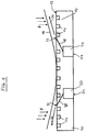
- Fig. 1 shows a cross section of a preferred embodiment of the device for controlling the temperature of a substrate (Thermochuck) and in particular a wafer.
- a main body 10 has a substantially planar abutment surface 12 in which a plurality of suction grooves 14 are formed. These suction grooves 14 are connected via not shown formed in the interior of the main body vacuum channels with at least one vacuum connection, also not shown. Via these suction grooves 14, a substrate 16 to be arranged on the abutment surface can be sucked towards the abutment surface and held against the abutment surface. For an effective suction process, however, the substrate 16 must already be approximated relatively close to the contact surface. In the in Fig.
- a thin, curved substrate 16 and in particular a thin wafer with a deflection should be tempered.
- This substrate 16 is approximated to the contact surface 12, wherein a convex surface of the substrate 16 faces the contact surface 12.
- the edge regions of the curved substrate 16 must first be brought into the vicinity of the contact surface 12, in order then to enable effective suction of the substrate 16 against the contact surface 12 via the suction grooves 14.
- fluid flow channels 18 as substantially rectilinear bores with a diameter of preferably formed about 0.6 mm, extending from compressed air channels 20 in the interior of the main body 10 to fluid outlet openings 22 in the contact surface 12.
- the fluid is conducted via the fluid flow channels 18 to the contact surface 12 and opens via the fluid outlet openings 22 into the space between the contact surface 12 and the substrate 16.
- the fluid preferably opens at an angle of about 60 ° to the normal direction of the contact surface.
- fluid flows 26 are formed substantially in extension from the directions of the fluid flow channels 18, which essentially have flow components parallel to the contact surface 12 or to the substrate 16.
- the device is thus designed to supply via the fluid supply port 24 a fluid, in particular a gas, into the fluid flow channel 18, which is preferably tubular in the interior of the main body 10 and directs the supplied fluid to the fluid outlet opening 22 in the contact surface 12.
- the fluid emerging from the fluid outlet opening 22 in the device forms a fluid flow 26 between the contact surface 12 and a substrate 16 located in the vicinity of the contact surface 12, which flow runs at least partially substantially parallel to the contact surface 12 and in the peripheral region of the contact surface 12 or . of the substrate 16 from the gap between contact surface 12 and substrate 16 exits.
- a relationship between the flow rate of a fluid and its static pressure means that with increasing flow velocity of a fluid, the static pressure in the fluid decreases. This relationship applies to both liquids and gases.
- the present device can thus be used with any fluids.
- the formation of a gas stream is just as conceivable as the formation of a liquid stream.
- Particularly preferred is the present device designed for use with compressed air. But it could also be used other gases such as nitrogen or noble gases.
- This effect causes in the present device, that decreases with increasing flow velocity of the fluid flow or the fluid flows 26 between the contact surface 12 and substrate 16 whose static pressure.
- the formation of the fluid stream 26 thus reduces the static pressure between the contact surface 12 and the substrate 16, while the static pressure of a fluid surrounding the substrate 16 in the remaining region is substantially not changes.
- the static pressure of the fluid in the area of the fluid streams 26 is markedly reduced compared to the environment in which the fluid has no flow or at least a significantly lower flow velocity.
- the resulting difference in static pressure above and below the substrate ie the difference of the compressive forces on the surface of the substrate facing the contact surface and the surface of the substrate facing away from the contact surface, causes an effective total force F on the substrate in the direction of the contact surface.
- This will be the in Fig. 1 shown bent substrate pressed in particular in the edge region in the direction of the contact surface or pulled and moved with sufficient elasticity of the substrate in the direction of the contact surface.
- the force F leads to a bending of the bent or curved substrate 16 or wafer and thus to a preferably planar or large-area, and particularly preferably substantially full-surface approach to the contact surface 12.
- the gap between the contact surface 12 and the substrate 16 decreases, whereby at constant fluid flow, the flow velocity in the fluid streams 26 increases, resulting in a further increase in the force acting on the substrate 16 force F.
- this effect has a self-reinforcing effect.
- the force F acting on the substrate 16 advantageously brings about at least partial adaptation of the shape of the substrate 16 to the contact surface 12
- thin bent wafers are brought by means of the forming force F in a planar shape and placed on a flat contact surface 12 of the present device, without the need for further mechanical means would be necessary to bend the substrate 16 in a plane.
- the substrate 16 After sufficient approximation of the substrate 16 to the contact surface 12 by the force F, the substrate can be maintained in the edge regions by suction via the suction grooves 14 on the contact surface 12.
- the fluid supply is interrupted by the fluid supply ports 24 again, so that no more fluid exits through the fluid outlet openings 22 in the space between the contact surface 12 and substrate 16.
- the substrate After the interruption of the fluid streams 26, the substrate is held in contact with the contact surface 12 and thus in good thermal contact with the main body 10 solely by suction or vacuum application by means of the suction grooves 14. By tempering the main body 10, the substrate 16 can thus be tempered easily and reliably.
- the vacuum channels and the fluid flow channels 18 are not formed as separate channels but the fluid flow channels 18 serve simultaneously as vacuum channels.
- the fluid flow channels preferably open into vacuum grooves.
- the fluid outlet openings are thus preferably formed in the vacuum grooves or as vacuum grooves.
- the substrate 16 in the vicinity of the contact surface 12th has been pulled or pressed, the fluid flow or the fluid flow is interrupted by the fluid flow channels 18 and generated in the fluid flow channels instead of a negative pressure or a vacuum.
- the substrate 16 is preferably further drawn or sucked to the contact surface 12, and held on the contact surface.
- the switching from the fluid flow to the vacuum is preferably carried out so fast that the substrate 16 is preferably not substantially or only slightly removed from the contact surface 12 during this.
- a switching valve is provided, by means of which the fluid flow channels 18 or vacuum channels can be connected depending on the valve position with a fluid pressure supply device or a vacuum supply device.
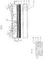
- Fig. 2 shows a cross section of another preferred embodiment of the device for controlling the temperature of a substrate (Thermochuck) and in particular a wafer.
- the main body 10 is arranged indirectly via shielding means 28 on a base plate 30.
- a heater 32 is provided such that it is also electrically isolated by the shielding means 28 of the main body 10.
- the heating device 32 serves, in particular, for controlling the temperature of the main body 10 and thus indirectly for controlling the temperature of the substrate 16.
- the shielding means 28 advantageously make it possible to apply the substrate 16 resting against the main body 10 or its contact surface 12 with a very high test voltage or current to operate or test.
- the main body 10 has at least one high-voltage and / or high-current connection 42, via which a voltage of up to approximately 8 kV can be supplied to the main body 10. But it can also be provided voltages up to about 10 kV.
- the shielding means 28 isolate the heater 32 from the main body 10th
- the shielding means 28 are particularly advantageously formed so that they are formed of two insulating layers 34 which are separated by a preferably grounded screen 36.
- the insulating layers 34 have advantageously a dielectric strength of about 10 kV.
- the device may additionally include a sensor 38 embedded in the main body 10.
- the sensor 38 may measure temperature, voltage, or current. It is understood that the sensor 38 may also detect other or alternative parameters. In order to protect the sensor 38 from a voltage applied to the main body 10 electrical voltage, this is also advantageously electrically insulated by shielding means 40 of the main body 10.
- the shielding means 40 have - as shown above - at least two insulating layers 34, which are separated by a preferably grounded screen 36.
Landscapes
- Container, Conveyance, Adherence, Positioning, Of Wafer (AREA)
Claims (6)
- Procédé de régulation de la température d'un substrat (16) comprenant les étapes suivantes :a) Préparation d'un dispositif de régulation de la température d'un substrat (16) comportant un corps principal (10) avec une surface d'appui (12) et au moins un canal à vide, qui débouche dans au moins un orifice d'aspiration formé dans la surface d'appui (12) et qui est relié à un raccord au vide disposé en dehors de la surface d'appui (12) ;b) Rapprochement du substrat (16) contre la surface d'appui (12) du dispositif ;c) Création d'une force (F) sur le substrat (16) en direction de la surface d'appui (12) par la production d'un flux de fluide (26) entre le substrat (16) et la surface d'appui (12) ;d) Maintien du substrat (16) en contact thermique avec la surface d'appui (12) par l'aspiration du substrat (16) via au moins ledit orifice d'aspiration formé dans la surface d'appui (12) ; ete) Régulation de la température du substrat (16) se trouvant en contact thermique avec le dispositif au moyen de la surface d'appui (12) par la régulation de la température du corps principal (10) du dispositif,caractérisé en ce que
ledit orifice d'aspiration au moins est une rainure d'aspiration (14),
dans lequel ladite rainure d'aspiration (14) au moins
est disposée essentiellement sous une forme spiralée ou annulaire et concentrique autour d'un axe central, et que
le flux de fluide (26) généré au cours de l'étape c) est interrompu après le démarrage de l'étape d) du maintien du substrat (16). - Procédé selon la revendication 1, dans lequel l'étape d) du maintien du substrat (16) en contact thermique avec la surface d'appui (12) se déroule après l'étape c) de création d'une force (F) sur le substrat (16).
- Procédé selon l'une des revendications précédentes, dans lequel un substrat (16) présentant une surface principalement convexe du moins en partie est rapproché de la surface d'appui (12) au cours de l'étape b) du rapprochement du substrat (16) contre la surface d'appui (12) de telle façon que la surface du substrat (16) principalement convexe du moins en partie est tournée vers la surface d'appui (12) du corps principal (10).
- Procédé selon l'une des revendications précédentes, dans lequel le substrat (16) est mis en contact mécanique avec la surface d'appui (12) au cours de l'étape b) du rapprochement du substrat (16) contre la surface d'appui (12).
- Procédé selon l'une des revendications précédentes, dans lequel une pression de fluide est fournie par l'apport d'un fluide au niveau au moins d'un raccord d'alimentation en fluide (24) au cours de l'étape c) servant à la production du flux de fluide (26) entre le substrat (16) et la surface d'appui (12).
- Procédé selon la revendication 5, dans lequel la pression de fluide fournie au niveau au moins dudit raccord d'alimentation en fluide (24) est établie en fonction d'une convexité et/ou d'une élasticité du substrat (16).
Applications Claiming Priority (1)
| Application Number | Priority Date | Filing Date | Title |
|---|---|---|---|
| PCT/EP2006/012005 WO2008071211A1 (fr) | 2006-12-13 | 2006-12-13 | Dispositif et procédé de régulation de la température d'un substrat |
Publications (2)
| Publication Number | Publication Date |
|---|---|
| EP2102894A1 EP2102894A1 (fr) | 2009-09-23 |
| EP2102894B1 true EP2102894B1 (fr) | 2019-04-17 |
Family
ID=38567014
Family Applications (1)
| Application Number | Title | Priority Date | Filing Date |
|---|---|---|---|
| EP06840969.7A Active EP2102894B1 (fr) | 2006-12-13 | 2006-12-13 | Procédé de régulation de la température d'un substrat |
Country Status (2)
| Country | Link |
|---|---|
| EP (1) | EP2102894B1 (fr) |
| WO (1) | WO2008071211A1 (fr) |
Citations (3)
| Publication number | Priority date | Publication date | Assignee | Title |
|---|---|---|---|---|
| JPS593945A (ja) * | 1982-06-29 | 1984-01-10 | Matsushita Electric Works Ltd | ウエハ−の吸着装置 |
| US4566726A (en) * | 1984-06-13 | 1986-01-28 | At&T Technologies, Inc. | Method and apparatus for handling semiconductor wafers |
| EP1215716A1 (fr) * | 2000-12-13 | 2002-06-19 | Infineon Technologies AG | moyens de support |
Family Cites Families (5)
| Publication number | Priority date | Publication date | Assignee | Title |
|---|---|---|---|---|
| JP3938610B2 (ja) * | 1997-03-14 | 2007-06-27 | 昌之 都田 | 基体の浮上装置並びに基体浮上型の加熱装置及び製膜装置 |
| US6636062B2 (en) * | 2001-04-10 | 2003-10-21 | Delta Design, Inc. | Temperature control device for an electronic component |
| JP3761444B2 (ja) * | 2001-10-23 | 2006-03-29 | 富士通株式会社 | 半導体装置の製造方法 |
| DE10319272A1 (de) * | 2003-04-29 | 2004-11-25 | Infineon Technologies Ag | Multifunktionsträger sowie zugehörige Andockstation |
| DE102005014513B4 (de) | 2005-03-30 | 2011-05-12 | Att Advanced Temperature Test Systems Gmbh | Vorrichtung und Verfahren zum Temperieren eines Substrats, sowie Verfahren zur Herstellung der Vorrichtung |
-
2006
- 2006-12-13 WO PCT/EP2006/012005 patent/WO2008071211A1/fr not_active Ceased
- 2006-12-13 EP EP06840969.7A patent/EP2102894B1/fr active Active
Patent Citations (3)
| Publication number | Priority date | Publication date | Assignee | Title |
|---|---|---|---|---|
| JPS593945A (ja) * | 1982-06-29 | 1984-01-10 | Matsushita Electric Works Ltd | ウエハ−の吸着装置 |
| US4566726A (en) * | 1984-06-13 | 1986-01-28 | At&T Technologies, Inc. | Method and apparatus for handling semiconductor wafers |
| EP1215716A1 (fr) * | 2000-12-13 | 2002-06-19 | Infineon Technologies AG | moyens de support |
Also Published As
| Publication number | Publication date |
|---|---|
| EP2102894A1 (fr) | 2009-09-23 |
| WO2008071211A1 (fr) | 2008-06-19 |
Similar Documents
| Publication | Publication Date | Title |
|---|---|---|
| DE69530801T2 (de) | Montageelement und methode zum klemmen eines flachen, dünnen und leitfähigen werkstückes | |
| DE69211508T2 (de) | Verfahren und Geräte zur Einschränkung des Plasma-Ätzgebietes zur Erlangung präziser Formgestaltung von Substratöberflächen | |
| EP3433875B1 (fr) | Procédé de liaison de substrats | |
| EP3640975B1 (fr) | Dispositif et procédé de liaison de substrats | |
| DE3317967C2 (de) | Vorrichtung zum Erzielen von Wärmeübergang zwischen einem Halbleiterplättchen und einer Aufspannplatte | |
| EP3005407B1 (fr) | Procédé pour lier des substrats | |
| EP3227907B1 (fr) | Procédé de collage de substrats | |
| DE3889649T2 (de) | Ätzverfahren und -gerät. | |
| EP2659279B1 (fr) | Dispositif pour l'essai haute tension de dispositifs à semi-conducteurs | |
| EP3497712B1 (fr) | Procédé et porte-échantillon pour lier des substrats de façon commandée | |
| DE69427645T2 (de) | Apparat zur handhabung von prozess fluiden | |
| AT525156A1 (de) | Bondvorrichtung sowie Verfahren zum Bonden von Substraten | |
| EP1473764A2 (fr) | Support multifonctionnel pour substrat | |
| DE102007032496B3 (de) | Vorrichtung zur Erzeugung eines Plasma-Jets | |
| EP2102894B1 (fr) | Procédé de régulation de la température d'un substrat | |
| EP4173028B1 (fr) | Procédé et dispositif de collage de substrats | |
| DD271776A1 (de) | Vorrichtung zur gaszufuehrung und -ableitung fuer die gasphasenbearbeitung von werkstuecken | |
| EP3014287A1 (fr) | Dispositif d'essai permettant l'essai électrique d'un échantillon électrique | |
| WO2000030146A1 (fr) | Procede et dispositif pour la sensibilisation d'un substrat | |
| DE19853092B4 (de) | Übernahme- und Haltesystem für ein Substrat | |
| DE102005045080B4 (de) | Vorrichtung und Verfahren zum Temperieren eines Substrats | |
| EP4581668A1 (fr) | Support de substrat sous vide à joint à vide optimisé | |
| EP1590510B1 (fr) | Dispositif pour realiser des passages electriquement conducteurs dans une tranche de semi-conducteur, au moyen d'une migration thermique | |
| EP2630653B1 (fr) | Dispositif de revêtement d'une tranche | |
| DE69104128T2 (de) | Spannen eines Werkstücks. |
Legal Events
| Date | Code | Title | Description |
|---|---|---|---|
| PUAI | Public reference made under article 153(3) epc to a published international application that has entered the european phase |
Free format text: ORIGINAL CODE: 0009012 |
|
| 17P | Request for examination filed |
Effective date: 20090713 |
|
| AK | Designated contracting states |
Kind code of ref document: A1 Designated state(s): AT BE BG CH CY CZ DE DK EE ES FI FR GB GR HU IE IS IT LI LT LU LV MC NL PL PT RO SE SI SK TR |
|
| RAP1 | Party data changed (applicant data changed or rights of an application transferred) |
Owner name: ATT ADVANCED TEMPERATURE TEST SYSTEMS GMBH |
|
| 111Z | Information provided on other rights and legal means of execution |
Free format text: AT BE BG CH CY CZ DE DK EE ES FI FR GB GR HU IE IS IT LT LU LV MC NL PL PT RO SE SI SK TR Effective date: 20091216 |
|
| DAX | Request for extension of the european patent (deleted) | ||
| 17Q | First examination report despatched |
Effective date: 20110421 |
|
| D11X | Information provided on other rights and legal means of execution (deleted) | ||
| STAA | Information on the status of an ep patent application or granted ep patent |
Free format text: STATUS: EXAMINATION IS IN PROGRESS |
|
| REG | Reference to a national code |
Ref country code: DE Ref legal event code: R079 Ref document number: 502006016231 Country of ref document: DE Free format text: PREVIOUS MAIN CLASS: H01L0021000000 Ipc: H01L0021670000 |
|
| GRAP | Despatch of communication of intention to grant a patent |
Free format text: ORIGINAL CODE: EPIDOSNIGR1 |
|
| STAA | Information on the status of an ep patent application or granted ep patent |
Free format text: STATUS: GRANT OF PATENT IS INTENDED |
|
| RIC1 | Information provided on ipc code assigned before grant |
Ipc: H01L 21/67 20060101AFI20180921BHEP Ipc: H01L 21/683 20060101ALI20180921BHEP |
|
| INTG | Intention to grant announced |
Effective date: 20181016 |
|
| GRAS | Grant fee paid |
Free format text: ORIGINAL CODE: EPIDOSNIGR3 |
|
| GRAA | (expected) grant |
Free format text: ORIGINAL CODE: 0009210 |
|
| STAA | Information on the status of an ep patent application or granted ep patent |
Free format text: STATUS: THE PATENT HAS BEEN GRANTED |
|
| AK | Designated contracting states |
Kind code of ref document: B1 Designated state(s): AT BE BG CH CY CZ DE DK EE ES FI FR GB GR HU IE IS IT LI LT LU LV MC NL PL PT RO SE SI SK TR |
|
| REG | Reference to a national code |
Ref country code: GB Ref legal event code: FG4D Free format text: NOT ENGLISH |
|
| REG | Reference to a national code |
Ref country code: CH Ref legal event code: EP |
|
| REG | Reference to a national code |
Ref country code: DE Ref legal event code: R096 Ref document number: 502006016231 Country of ref document: DE |
|
| REG | Reference to a national code |
Ref country code: AT Ref legal event code: REF Ref document number: 1122488 Country of ref document: AT Kind code of ref document: T Effective date: 20190515 Ref country code: IE Ref legal event code: FG4D Free format text: LANGUAGE OF EP DOCUMENT: GERMAN |
|
| REG | Reference to a national code |
Ref country code: NL Ref legal event code: FP |
|
| REG | Reference to a national code |
Ref country code: LT Ref legal event code: MG4D |
|
| PG25 | Lapsed in a contracting state [announced via postgrant information from national office to epo] |
Ref country code: LT Free format text: LAPSE BECAUSE OF FAILURE TO SUBMIT A TRANSLATION OF THE DESCRIPTION OR TO PAY THE FEE WITHIN THE PRESCRIBED TIME-LIMIT Effective date: 20190417 Ref country code: SE Free format text: LAPSE BECAUSE OF FAILURE TO SUBMIT A TRANSLATION OF THE DESCRIPTION OR TO PAY THE FEE WITHIN THE PRESCRIBED TIME-LIMIT Effective date: 20190417 Ref country code: PT Free format text: LAPSE BECAUSE OF FAILURE TO SUBMIT A TRANSLATION OF THE DESCRIPTION OR TO PAY THE FEE WITHIN THE PRESCRIBED TIME-LIMIT Effective date: 20190817 Ref country code: ES Free format text: LAPSE BECAUSE OF FAILURE TO SUBMIT A TRANSLATION OF THE DESCRIPTION OR TO PAY THE FEE WITHIN THE PRESCRIBED TIME-LIMIT Effective date: 20190417 Ref country code: FI Free format text: LAPSE BECAUSE OF FAILURE TO SUBMIT A TRANSLATION OF THE DESCRIPTION OR TO PAY THE FEE WITHIN THE PRESCRIBED TIME-LIMIT Effective date: 20190417 |
|
| PG25 | Lapsed in a contracting state [announced via postgrant information from national office to epo] |
Ref country code: GR Free format text: LAPSE BECAUSE OF FAILURE TO SUBMIT A TRANSLATION OF THE DESCRIPTION OR TO PAY THE FEE WITHIN THE PRESCRIBED TIME-LIMIT Effective date: 20190718 Ref country code: BG Free format text: LAPSE BECAUSE OF FAILURE TO SUBMIT A TRANSLATION OF THE DESCRIPTION OR TO PAY THE FEE WITHIN THE PRESCRIBED TIME-LIMIT Effective date: 20190717 Ref country code: PL Free format text: LAPSE BECAUSE OF FAILURE TO SUBMIT A TRANSLATION OF THE DESCRIPTION OR TO PAY THE FEE WITHIN THE PRESCRIBED TIME-LIMIT Effective date: 20190417 Ref country code: LV Free format text: LAPSE BECAUSE OF FAILURE TO SUBMIT A TRANSLATION OF THE DESCRIPTION OR TO PAY THE FEE WITHIN THE PRESCRIBED TIME-LIMIT Effective date: 20190417 |
|
| PG25 | Lapsed in a contracting state [announced via postgrant information from national office to epo] |
Ref country code: IS Free format text: LAPSE BECAUSE OF FAILURE TO SUBMIT A TRANSLATION OF THE DESCRIPTION OR TO PAY THE FEE WITHIN THE PRESCRIBED TIME-LIMIT Effective date: 20190817 |
|
| REG | Reference to a national code |
Ref country code: DE Ref legal event code: R097 Ref document number: 502006016231 Country of ref document: DE |
|
| PG25 | Lapsed in a contracting state [announced via postgrant information from national office to epo] |
Ref country code: EE Free format text: LAPSE BECAUSE OF FAILURE TO SUBMIT A TRANSLATION OF THE DESCRIPTION OR TO PAY THE FEE WITHIN THE PRESCRIBED TIME-LIMIT Effective date: 20190417 Ref country code: DK Free format text: LAPSE BECAUSE OF FAILURE TO SUBMIT A TRANSLATION OF THE DESCRIPTION OR TO PAY THE FEE WITHIN THE PRESCRIBED TIME-LIMIT Effective date: 20190417 Ref country code: SK Free format text: LAPSE BECAUSE OF FAILURE TO SUBMIT A TRANSLATION OF THE DESCRIPTION OR TO PAY THE FEE WITHIN THE PRESCRIBED TIME-LIMIT Effective date: 20190417 Ref country code: CZ Free format text: LAPSE BECAUSE OF FAILURE TO SUBMIT A TRANSLATION OF THE DESCRIPTION OR TO PAY THE FEE WITHIN THE PRESCRIBED TIME-LIMIT Effective date: 20190417 Ref country code: RO Free format text: LAPSE BECAUSE OF FAILURE TO SUBMIT A TRANSLATION OF THE DESCRIPTION OR TO PAY THE FEE WITHIN THE PRESCRIBED TIME-LIMIT Effective date: 20190417 |
|
| PLBE | No opposition filed within time limit |
Free format text: ORIGINAL CODE: 0009261 |
|
| STAA | Information on the status of an ep patent application or granted ep patent |
Free format text: STATUS: NO OPPOSITION FILED WITHIN TIME LIMIT |
|
| 26N | No opposition filed |
Effective date: 20200120 |
|
| PG25 | Lapsed in a contracting state [announced via postgrant information from national office to epo] |
Ref country code: TR Free format text: LAPSE BECAUSE OF FAILURE TO SUBMIT A TRANSLATION OF THE DESCRIPTION OR TO PAY THE FEE WITHIN THE PRESCRIBED TIME-LIMIT Effective date: 20190417 |
|
| PG25 | Lapsed in a contracting state [announced via postgrant information from national office to epo] |
Ref country code: SI Free format text: LAPSE BECAUSE OF FAILURE TO SUBMIT A TRANSLATION OF THE DESCRIPTION OR TO PAY THE FEE WITHIN THE PRESCRIBED TIME-LIMIT Effective date: 20190417 |
|
| REG | Reference to a national code |
Ref country code: CH Ref legal event code: PL |
|
| PG25 | Lapsed in a contracting state [announced via postgrant information from national office to epo] |
Ref country code: MC Free format text: LAPSE BECAUSE OF FAILURE TO SUBMIT A TRANSLATION OF THE DESCRIPTION OR TO PAY THE FEE WITHIN THE PRESCRIBED TIME-LIMIT Effective date: 20190417 |
|
| GBPC | Gb: european patent ceased through non-payment of renewal fee |
Effective date: 20191213 |
|
| PG25 | Lapsed in a contracting state [announced via postgrant information from national office to epo] |
Ref country code: GB Free format text: LAPSE BECAUSE OF NON-PAYMENT OF DUE FEES Effective date: 20191213 Ref country code: IE Free format text: LAPSE BECAUSE OF NON-PAYMENT OF DUE FEES Effective date: 20191213 Ref country code: LU Free format text: LAPSE BECAUSE OF NON-PAYMENT OF DUE FEES Effective date: 20191213 |
|
| PG25 | Lapsed in a contracting state [announced via postgrant information from national office to epo] |
Ref country code: CH Free format text: LAPSE BECAUSE OF NON-PAYMENT OF DUE FEES Effective date: 20191231 Ref country code: LI Free format text: LAPSE BECAUSE OF NON-PAYMENT OF DUE FEES Effective date: 20191231 |
|
| PG25 | Lapsed in a contracting state [announced via postgrant information from national office to epo] |
Ref country code: CY Free format text: LAPSE BECAUSE OF FAILURE TO SUBMIT A TRANSLATION OF THE DESCRIPTION OR TO PAY THE FEE WITHIN THE PRESCRIBED TIME-LIMIT Effective date: 20190417 |
|
| PG25 | Lapsed in a contracting state [announced via postgrant information from national office to epo] |
Ref country code: HU Free format text: LAPSE BECAUSE OF FAILURE TO SUBMIT A TRANSLATION OF THE DESCRIPTION OR TO PAY THE FEE WITHIN THE PRESCRIBED TIME-LIMIT; INVALID AB INITIO Effective date: 20061213 |
|
| PGFP | Annual fee paid to national office [announced via postgrant information from national office to epo] |
Ref country code: NL Payment date: 20221220 Year of fee payment: 17 |
|
| PGFP | Annual fee paid to national office [announced via postgrant information from national office to epo] |
Ref country code: BE Payment date: 20221220 Year of fee payment: 17 |
|
| REG | Reference to a national code |
Ref country code: NL Ref legal event code: MM Effective date: 20240101 |
|
| REG | Reference to a national code |
Ref country code: BE Ref legal event code: MM Effective date: 20231231 |
|
| PG25 | Lapsed in a contracting state [announced via postgrant information from national office to epo] |
Ref country code: NL Free format text: LAPSE BECAUSE OF NON-PAYMENT OF DUE FEES Effective date: 20240101 |
|
| PG25 | Lapsed in a contracting state [announced via postgrant information from national office to epo] |
Ref country code: NL Free format text: LAPSE BECAUSE OF NON-PAYMENT OF DUE FEES Effective date: 20240101 |
|
| PG25 | Lapsed in a contracting state [announced via postgrant information from national office to epo] |
Ref country code: BE Free format text: LAPSE BECAUSE OF NON-PAYMENT OF DUE FEES Effective date: 20231231 |
|
| PG25 | Lapsed in a contracting state [announced via postgrant information from national office to epo] |
Ref country code: BE Free format text: LAPSE BECAUSE OF NON-PAYMENT OF DUE FEES Effective date: 20231231 |
|
| REG | Reference to a national code |
Ref country code: DE Ref legal event code: R079 Ref document number: 502006016231 Country of ref document: DE Free format text: PREVIOUS MAIN CLASS: H01L0021670000 Ipc: H10P0072000000 |
|
| PGFP | Annual fee paid to national office [announced via postgrant information from national office to epo] |
Ref country code: AT Payment date: 20251215 Year of fee payment: 20 |
|
| PGFP | Annual fee paid to national office [announced via postgrant information from national office to epo] |
Ref country code: FR Payment date: 20251223 Year of fee payment: 20 |
|
| PGFP | Annual fee paid to national office [announced via postgrant information from national office to epo] |
Ref country code: DE Payment date: 20251223 Year of fee payment: 20 |
|
| PGFP | Annual fee paid to national office [announced via postgrant information from national office to epo] |
Ref country code: IT Payment date: 20251231 Year of fee payment: 20 |