EP2103203A2 - Verfahren zur Bestimmung einer kritischen Verringerung der Wellengeschwindigkeit einer Bearbeitungsmaschine - Google Patents
Verfahren zur Bestimmung einer kritischen Verringerung der Wellengeschwindigkeit einer Bearbeitungsmaschine Download PDFInfo
- Publication number
- EP2103203A2 EP2103203A2 EP09153564A EP09153564A EP2103203A2 EP 2103203 A2 EP2103203 A2 EP 2103203A2 EP 09153564 A EP09153564 A EP 09153564A EP 09153564 A EP09153564 A EP 09153564A EP 2103203 A2 EP2103203 A2 EP 2103203A2
- Authority
- EP
- European Patent Office
- Prior art keywords
- rotational speed
- monitored shaft
- shaft
- monitored
- crankshaft
- Prior art date
- Legal status (The legal status is an assumption and is not a legal conclusion. Google has not performed a legal analysis and makes no representation as to the accuracy of the status listed.)
- Granted
Links
Images


Classifications
-
- A—HUMAN NECESSITIES
- A01—AGRICULTURE; FORESTRY; ANIMAL HUSBANDRY; HUNTING; TRAPPING; FISHING
- A01D—HARVESTING; MOWING
- A01D41/00—Combines, i.e. harvesters or mowers combined with threshing devices
- A01D41/12—Details of combines
- A01D41/127—Control or measuring arrangements specially adapted for combines
Definitions
- the present invention is directed to a work machine, and, more particularly, to a method for determining a critical reduction in shaft speed in a work machine.
- Agricultural combines are engine powered machines that harvest, thresh, separate and clean an agricultural crop.
- the resulting clean grain is stored in a grain tank located on the combine.
- the clean grain can then be transported from the grain tank to a truck, grain cart or other receiving bin by an unloading auger.
- Agricultural combines have several rotating shafts (e.g., rotor, clean grain elevator, etc.) that are monitored for changes in speed.
- shafts e.g., rotor, clean grain elevator, etc.
- a large table is maintained that indicates the allowed speed range for each shaft based on machine type and other customer settings.
- a low shaft speed alarm is activated to notify the operator.
- the invention in one form thereof is directed to a method for determining a critical reduction in shaft speed in a work machine having at least one monitored shaft driven by a crankshaft of an engine.
- the method includes determining an actual rotational speed of the crankshaft; determining an actual rotational speed of a first monitored shaft; determining a filtered rotational speed of the first monitored shaft based on an algorithm that utilizes the actual rotational speed of the first monitored shaft, the actual rotational speed of the crankshaft, and a reference rotational speed of the crankshaft; comparing the filtered rotational speed of the first monitored shaft to the actual rotational speed of the first monitored shaft; determining whether the actual rotational speed of the first monitored shaft deviates from the filtered rotational speed of the first monitored shaft by a predetermined amount; and activating an alarm if the actual rotational speed of the first monitored shaft deviates from the filtered rotational speed of the first monitored shaft by the predetermined amount.
- the invention in another form thereof, is directed to a method for determining a critical reduction in shaft speed in a work machine having at least one monitored shaft driven by a crankshaft of an engine.
- the method includes determining an actual rotational speed of the crankshaft; determining an actual rotational speed of a first monitored shaft; determining a biased rotational speed of the first monitored shaft based at least on the actual rotational speed of the first monitored shaft, the actual rotational speed of the crankshaft, and a reference rotational speed of the crankshaft; determining a filtered rotational speed of the first monitored shaft by passing the biased rotational speed of the first monitored shaft through a low-pass filter; comparing the filtered rotational speed of the first monitored shaft to the actual rotational speed of the first monitored shaft; determining whether the actual rotational speed of the first monitored shaft deviates from the filtered rotational speed of the first monitored shaft by a predetermined amount; and activating an alarm if the actual rotational speed of the first monitored shaft deviates from the filtered rotational speed of the first
- the invention in another form thereof, is directed to a work machine.
- the work machine includes an engine having a crankshaft.
- a work assembly is configured to perform a work function.
- the work assembly has at least one monitored shaft drivably coupled to the crankshaft of the engine.
- a shaft monitor system has a monitor and a plurality of sensors communicatively coupled to the monitor.
- the plurality of sensors monitor a rotational speed of the crankshaft and the at least one monitored shaft.
- the monitor includes a controller and an alarm.
- the monitor executes program instructions to identify a critical reduction in shaft speed of each monitored shaft.
- the program instructions perform the acts of determining an actual rotational speed of the crankshaft; determining an actual rotational speed of a first monitored shaft; determining a filtered rotational speed of the first monitored shaft based on an algorithm that utilizes the actual rotational speed of the first monitored shaft, the actual rotational speed of the crankshaft, and a reference rotational speed of the crankshaft; comparing the filtered rotational speed of the first monitored shaft to the actual rotational speed of the first monitored shaft; determining whether the actual rotational speed of the first monitored shaft deviates from the filtered rotational speed of the first monitored shaft by a predetermined amount; and activating the alarm if the actual rotational speed of the first monitored shaft deviates from the filtered rotational speed of the first monitored shaft by the predetermined amount.
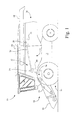
- a work machine 10 in the form of a self-propelled agricultural combine.
- a work machine 10 in the form of a self-propelled agricultural combine.
- the invention is being described as being incorporated into a combine, it is contemplated that the present invention may be used with other types of work machines having one or more monitored rotatable shafts.
- Work machine 10 in the form of an agricultural combine, includes a supporting structure 12.
- An elevated operator's station 14 is mounted at the front of work machine 10.
- a propulsion unit 16 which may include tires and/or tracks that engage the ground, is coupled to supporting structure 12, and performs propulsion and/or steering functions.
- a work assembly 18 is coupled to supporting structure 12, and is configured to perform a work function.
- work assembly 18 may include a harvesting platform 20, a feederhouse 22, a main separator unit 24, and a crop residue processing unit 26.
- Harvesting platform 20, such as a corn head, bean head, etc. is used for harvesting a crop and directing the crop to feederhouse 22.
- the harvested crop is directed by feederhouse 22 to main separator unit 24, which performs threshing, separating and cleaning operations.
- Crop residue is then directed to crop residue processing unit 26, which in turn may further shred and spread the crop residue over the field.
- a transversely oriented internal combustion engine 28 provides the mechanical power needed to perform the propulsion, harvesting, threshing, separating, cleaning, and crop residue processing operations.
- Engine 28 includes a crankshaft 30 coupled to a belt-type drive system 32.
- Belt-type drive system 32 includes a primary countershaft 34 connected to crankshaft 30 of engine 28 by a shaft and gearbox configuration 36, which is schematically illustrated.
- a variable speed assembly 38 is connected to the primary countershaft 34 by a drive belt 40, which in turn is coupled to various rotatable shafts in one or more of harvesting platform 20, feederhouse 22, main separator unit 24, and crop residue processing unit 26.
- harvesting platform 20 facilitates harvesting a crop and directing the crop to feederhouse 22.
- the harvested crop is directed by feederhouse 22 to main separator unit 24.
- Main separator unit 24 includes a feed accelerator 42, which directs the harvested crop upwardly through an inlet transition section 44 to an axial crop processing unit 46.
- Axial crop processing unit 46 is located between, and may be supported by the side sheets of work machine 10 and supporting structure 12.
- Axial crop processing unit 46 includes an axial rotor housing 48 and an axial rotor 50 located in axial rotor housing 48.
- the harvested crop enters axial rotor housing 48 through inlet transition section 44.
- Axial rotor 50 is provided with an infeed portion, a threshing portion and a separating portion.
- Axial rotor housing 48 has a corresponding infeed section, a threshing section and a separating section.
- Both crop processing portions, the threshing portion and the separating portion, are provided with crop engaging assemblies.
- the threshing section of the axial rotor housing 48 is provided with a concave and the separating section is provided with a grate. Grain and chaff released from the crop mat falls through the concave and the grate.
- the concave and grate prevent the passage of crop material larger than grain or chaff from entering a cleaning system 52, which includes a cleaning fan 54.
- Grain and chaff falling through the concave and grate is directed to cleaning system 52 which removes the chaff from the grain.
- a tailings auger 56 directs returns collected at the bottom of cleaning system 52 to tailings elevator 58 for redelivery to cleaning system 52 for reprocessing.
- the clean grain is directed by a clean grain auger 60 to a clean grain elevator 62, and in turn to a fountain auger 64.
- Fountain auger 64 directs the grain into a grain tank, or grain compartment, 66. The grain is removed from the grain tank 66 by an unloading auger 68.
- Crop residue processing unit 26 includes, for example, a beater 70 that propels the crop residue out the rear of the combine. Crop residue processing unit 26 may further include, for example, a straw chopper (not shown).
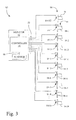
- Shaft monitor system 80 has a monitor 82 and a plurality of sensors 84.
- Monitor 82 may be mounted in the operator's station 14, and includes a controller 86 communicatively coupled to an alarm 88 by a wired connection 90.
- the plurality of sensors 84 is communicatively coupled to controller 86 of monitor 82 by a communication link 92, such as for example, a multi-conductor cable.
- Controller 86 may be configured from hardware only, or hardware that utilizes firmware/software, that performs a predefined shaft monitoring operation.
- controller 86 may be configured with a microprocessor and associated memory, with the instructions for performing a shaft monitoring operation being stored in the memory.
- the shaft monitoring routine may be hardwired in logic, such as in the form of an application specific integrated circuit (ASIC).
- ASIC application specific integrated circuit
- Alarm 88 may provide an audio and/or visual alarm indication that is perceptible by an operator of work machine 10.
- an audio alarm indication may be a repetitive tone, or beep
- a visual alarm indication by be an illumination of a indicator light, or illumination of a portion of a diagrammatic picture of the monitored shafts.
- the plurality of sensors 84 may be used to monitor a rotational speed of crankshaft 30 and a rotational speed of a plurality of monitored shafts 94, individually identified as monitored shafts, 94-1, 94-2, 94-3, 94-4, 94-5, 94-6, 94-7, 94-8...94-N in the present embodiment, wherein N represents some finite number of monitored shafts.
- Each of the plurality of sensors 84 may be a sensor configuration known in the art, such as an inductive sensor arrangement, an optical sensor arrangement, a Hall-effect sensor arrangement, etc.
- monitored shafts 94-1, 94-2, 94-3, 94-4, 94-5, 94-6, 94-7, 94-8...94-N may be shafts, for example, respectively associated with feed accelerator 42, axial rotor 50, cleaning fan 54, tailings elevator 58, clean grain auger 60, clean grain elevator 62, discharge beater 70, and a straw chopper (optional).
- Each of the plurality of monitored shafts 94 is driven, indirectly or directly, by crankshaft 30 of internal combustion engine 28.
- crankshaft 30 of internal combustion engine 28 Those skilled in the art will recognize that the number of monitored shafts may be increased or decreased from that shown in the present exemplary embodiment.
- Fig. 4 is a flowchart of a method for determining a critical reduction in shaft speed in a work machine, such as work machine 10, in accordance with an embodiment of the present invention. The method may be performed, for example, as program instructions executed by the shaft monitor system 80 of Fig. 3 .
- an actual rotational speed of the engine crankshaft is determined.
- the actual rotational speed of crankshaft 30 of engine 28 may be determined, for example, by sensor 84-EC generating a signal corresponding to the rotational speed of crankshaft 30, which in turn supplies the signal representing the actual rotational speed of crankshaft 30 to controller 86 of monitor 82.
- the initial signal may be indicative of a rotational frequency, which is translated by controller 86 into revolutions per minute (RPM).
- RPM revolutions per minute
- SpeedRPM SpeedHz x60/PPR, wherein SpeedRPM is the actual rotational speed in RPM, SpeedHz is the actual rotational speed in Hertz (frequency), and PPR is the number of output pulses per revolution of the monitored shaft.
- an actual rotational speed of a monitored shaft is determined.
- the monitored shaft may be one of the plurality of monitored shafts 94 that is monitored by one of the corresponding plurality of sensors 84.
- the shaft of interest is monitored shaft 94-2 associated with axial rotor 50 that is being monitored by sensor 84-2.
- the initial signal may be indicative of rotational frequency of monitored shaft 94-2, which is translated by controller 86 into revolutions per minute (RPM).
- a biased rotational speed of the monitored shaft is determined based at least on actual rotational speed of the monitored shaft, e.g., monitored shaft 94-2, the actual rotational speed of crankshaft 30, and a reference rotational speed of crankshaft 30.
- the reference rotational speed of crankshaft 30 is a constant having a value corresponding to a rated maximum rotational speed of crankshaft 30 of engine 28. In one embodiment, for example, the reference rotational speed of crankshaft 30 is 2340 RPM.
- a filtered rotational speed of the monitored shaft is determined by passing the biased rotational speed of the monitored shaft through a low-pass filter.
- the filtering logic will prevent any alarms from being generated.
- shaft monitor system 80 may generate an alarm notifying the operator of the low shaft speed, if all other conditions for generating the alarm have been met.
- the filtered rotational speed of the monitored shaft is compared to the actual rotational speed of the monitored shaft.
- the predetermined amount is selected to be 25 percent. However, those skilled in the art will recognize that the predetermined amount may be selected to be higher or lower than 25 percent, depending on the application and the desired sensitivity to change.
- the predetermined time is two seconds.
- the predetermined time may be selected to be higher or lower than two seconds, depending on the application and the desired sensitivity to change.
- the process returns to act S100, and the process is repeated.
- alarm 88 is activated, e.g.,* by controller 86 of monitor 82, indicating that the monitored shaft, e.g., monitored shaft 94-2, has experienced a critical reduction in shaft speed.
- the operator of work machine 10 may then take corrective action to remove the cause of the alarm activation.
- the alarm may be reset, for example, each time feederhouse 22 is disengaged, at which time shaft monitor system 80 will be set to re-learn the actual shaft speeds, and re-calculate the associated filtered rotational speed of each monitored shaft when feederhouse 22 is reengaged. Also, this ensures that any configuration changes (e.g., low-speed versus high-speed settings) will not result in nuisance alarms.
- Fig. 4 has been described with respect to a single monitored shaft, e.g., monitored shaft 94-2. However, in operation each of the monitored shafts 94 may be monitored by the method described above, either concurrently or sequentially.
Landscapes
- Life Sciences & Earth Sciences (AREA)
- Environmental Sciences (AREA)
- Testing Of Devices, Machine Parts, Or Other Structures Thereof (AREA)
- Combined Controls Of Internal Combustion Engines (AREA)
- Combines (AREA)
- Milling Processes (AREA)
Applications Claiming Priority (1)
| Application Number | Priority Date | Filing Date | Title |
|---|---|---|---|
| US12/052,215 US7664615B2 (en) | 2008-03-20 | 2008-03-20 | Method for determining a critical reduction in shaft speed in a work machine |
Publications (3)
| Publication Number | Publication Date |
|---|---|
| EP2103203A2 true EP2103203A2 (de) | 2009-09-23 |
| EP2103203A3 EP2103203A3 (de) | 2010-11-24 |
| EP2103203B1 EP2103203B1 (de) | 2012-01-18 |
Family
ID=40786452
Family Applications (1)
| Application Number | Title | Priority Date | Filing Date |
|---|---|---|---|
| EP09153564A Active EP2103203B1 (de) | 2008-03-20 | 2009-02-25 | Verfahren zur Bestimmung einer kritischen Verringerung der Wellengeschwindigkeit einer Bearbeitungsmaschine |
Country Status (7)
| Country | Link |
|---|---|
| US (1) | US7664615B2 (de) |
| EP (1) | EP2103203B1 (de) |
| AR (1) | AR070985A1 (de) |
| AT (1) | ATE541449T1 (de) |
| BR (1) | BRPI0900475A2 (de) |
| RU (1) | RU2491554C2 (de) |
| UA (1) | UA102218C2 (de) |
Cited By (1)
| Publication number | Priority date | Publication date | Assignee | Title |
|---|---|---|---|---|
| EP4108567A4 (de) * | 2020-02-18 | 2023-07-26 | Denso Corporation | System zur diagnose von anomalien und verfahren zur diagnose von anomalien |
Families Citing this family (1)
| Publication number | Priority date | Publication date | Assignee | Title |
|---|---|---|---|---|
| US10481628B2 (en) * | 2015-09-23 | 2019-11-19 | Deere & Company | Surfacing of subsystem power consumption on an agricultural machine |
Citations (2)
| Publication number | Priority date | Publication date | Assignee | Title |
|---|---|---|---|---|
| US5855108A (en) | 1996-02-16 | 1999-01-05 | Case Corporation | Alarm monitor for belt slip in a combine |
| US5978720A (en) | 1993-12-08 | 1999-11-02 | Claas Ohg | Agricultural machine, especially combine harvester, with multi-processor guide system |
Family Cites Families (7)
| Publication number | Priority date | Publication date | Assignee | Title |
|---|---|---|---|---|
| JPH04209930A (ja) | 1990-12-11 | 1992-07-31 | Daihatsu Motor Co Ltd | エンジンのベルト異常検出装置 |
| RU2029306C1 (ru) * | 1992-04-27 | 1995-02-20 | Саратовский государственный технический университет | Устройство для измерения неравномерности скорости вращения вала |
| RU2020483C1 (ru) * | 1992-05-06 | 1994-09-30 | Саратовский государственный технический университет | Устройство для измерения неравномерности скорости вращения вала |
| RU2064171C1 (ru) * | 1993-02-11 | 1996-07-20 | Васильев Юрий Александрович | Способ диагностирования двигателя внутреннего сгорания |
| JP3427476B2 (ja) * | 1994-05-12 | 2003-07-14 | 株式会社デンソー | 車両用自動変速機における変速過渡制御方法 |
| JP4295962B2 (ja) * | 2002-07-29 | 2009-07-15 | アイシン精機株式会社 | 自動変速機の変速制御装置 |
| JP4209930B1 (ja) | 2008-02-07 | 2009-01-14 | 浩子 土屋 | 買物袋 |
-
2008
- 2008-03-20 US US12/052,215 patent/US7664615B2/en not_active Expired - Fee Related
-
2009
- 2009-02-25 EP EP09153564A patent/EP2103203B1/de active Active
- 2009-02-25 AT AT09153564T patent/ATE541449T1/de active
- 2009-03-05 RU RU2009107971/28A patent/RU2491554C2/ru not_active IP Right Cessation
- 2009-03-06 BR BRPI0900475-0A patent/BRPI0900475A2/pt not_active IP Right Cessation
- 2009-03-18 UA UAA200902404A patent/UA102218C2/ru unknown
- 2009-03-18 AR ARP090100976A patent/AR070985A1/es not_active Application Discontinuation
Patent Citations (2)
| Publication number | Priority date | Publication date | Assignee | Title |
|---|---|---|---|---|
| US5978720A (en) | 1993-12-08 | 1999-11-02 | Claas Ohg | Agricultural machine, especially combine harvester, with multi-processor guide system |
| US5855108A (en) | 1996-02-16 | 1999-01-05 | Case Corporation | Alarm monitor for belt slip in a combine |
Cited By (1)
| Publication number | Priority date | Publication date | Assignee | Title |
|---|---|---|---|---|
| EP4108567A4 (de) * | 2020-02-18 | 2023-07-26 | Denso Corporation | System zur diagnose von anomalien und verfahren zur diagnose von anomalien |
Also Published As
| Publication number | Publication date |
|---|---|
| UA102218C2 (ru) | 2013-06-25 |
| EP2103203B1 (de) | 2012-01-18 |
| RU2009107971A (ru) | 2010-09-10 |
| US7664615B2 (en) | 2010-02-16 |
| EP2103203A3 (de) | 2010-11-24 |
| BRPI0900475A2 (pt) | 2010-04-06 |
| RU2491554C2 (ru) | 2013-08-27 |
| AR070985A1 (es) | 2010-05-19 |
| ATE541449T1 (de) | 2012-02-15 |
| US20090240465A1 (en) | 2009-09-24 |
Similar Documents
| Publication | Publication Date | Title |
|---|---|---|
| US10645876B2 (en) | System and method for controlled cleaning in a cane harvester | |
| US10091934B2 (en) | System and method for controlled cleaning in a cane harvester | |
| US7648413B2 (en) | Combine harvester power management control | |
| US7544125B2 (en) | System and method for detecting a condition indicative of plugging of a discharge path of an agricultural combine | |
| EP1974598B1 (de) | System zur Entdeckung einer Luftstrombedingung die eine Verstopfung einer Entladevorrichtung an einem Mähdrescher anzeigt | |
| EP2127515B1 (de) | Kornreinigungsanordnung | |
| EP3672391B1 (de) | Verstellbares gebläse auf der grundlage des korndurchsatzes | |
| EP2798944B1 (de) | Verfahren zur Fernkonfiguration eines Restesystem einer landwirtschaftlichen Erntemaschine | |
| EP3597028B1 (de) | Gebläseantrieb in abhängigkeit von der last auf den reinigungsgebläseantrieb | |
| US11778947B2 (en) | Automated adjustable angle of incidence fan for cleaning sugarcane | |
| EP3153678A1 (de) | Landwirtschaftliche erntemaschine | |
| US12457932B2 (en) | Sensing array for grain tank | |
| EP3459339B1 (de) | Durch bediener verstellbare kontinuierliche behälterfüllstandsmessung | |
| EP2103203B1 (de) | Verfahren zur Bestimmung einer kritischen Verringerung der Wellengeschwindigkeit einer Bearbeitungsmaschine | |
| EP1044596B1 (de) | Alarmsystem für landwirtschaftliche Maschinen | |
| EP2111739B1 (de) | Steuerung des Leistungsmanagements einer kombinierten Erntemaschine | |
| CN104247607B (zh) | 一种收割产品溢出装置、农业收割机及其警示方法 | |
| EP4413849A1 (de) | System zur erkennung gebrochener paddel für einen aufzug eines mähdreschers | |
| JP5837836B2 (ja) | コンバインの管理システム | |
| EP1964461B1 (de) | Steuerung des Leistungsmanagements einer kombinierten Erntemaschine | |
| CN102045998B (zh) | 联合收割机的收割部 | |
| US20260123582A1 (en) | Non-contact crop moisture sensor for a sugarcane harvester | |
| Lasken et al. | Harvesting Equipment Electronics |
Legal Events
| Date | Code | Title | Description |
|---|---|---|---|
| PUAI | Public reference made under article 153(3) epc to a published international application that has entered the european phase |
Free format text: ORIGINAL CODE: 0009012 |
|
| AK | Designated contracting states |
Kind code of ref document: A2 Designated state(s): AT BE BG CH CY CZ DE DK EE ES FI FR GB GR HR HU IE IS IT LI LT LU LV MC MK MT NL NO PL PT RO SE SI SK TR |
|
| AX | Request for extension of the european patent |
Extension state: AL BA RS |
|
| PUAL | Search report despatched |
Free format text: ORIGINAL CODE: 0009013 |
|
| AK | Designated contracting states |
Kind code of ref document: A3 Designated state(s): AT BE BG CH CY CZ DE DK EE ES FI FR GB GR HR HU IE IS IT LI LT LU LV MC MK MT NL NO PL PT RO SE SI SK TR |
|
| AX | Request for extension of the european patent |
Extension state: AL BA RS |
|
| 17P | Request for examination filed |
Effective date: 20110524 |
|
| AKX | Designation fees paid |
Designated state(s): AT BE BG CH CY CZ DE DK EE ES FI FR GB GR HR HU IE IS IT LI LT LU LV MC MK MT NL NO PL PT RO SE SI SK TR |
|
| GRAP | Despatch of communication of intention to grant a patent |
Free format text: ORIGINAL CODE: EPIDOSNIGR1 |
|
| GRAS | Grant fee paid |
Free format text: ORIGINAL CODE: EPIDOSNIGR3 |
|
| GRAA | (expected) grant |
Free format text: ORIGINAL CODE: 0009210 |
|
| AK | Designated contracting states |
Kind code of ref document: B1 Designated state(s): AT BE BG CH CY CZ DE DK EE ES FI FR GB GR HR HU IE IS IT LI LT LU LV MC MK MT NL NO PL PT RO SE SI SK TR |
|
| REG | Reference to a national code |
Ref country code: GB Ref legal event code: FG4D |
|
| REG | Reference to a national code |
Ref country code: CH Ref legal event code: EP |
|
| REG | Reference to a national code |
Ref country code: IE Ref legal event code: FG4D Ref country code: AT Ref legal event code: REF Ref document number: 541449 Country of ref document: AT Kind code of ref document: T Effective date: 20120215 |
|
| REG | Reference to a national code |
Ref country code: DE Ref legal event code: R096 Ref document number: 602009004671 Country of ref document: DE Effective date: 20120322 |
|
| REG | Reference to a national code |
Ref country code: NL Ref legal event code: VDEP Effective date: 20120118 |
|
| LTIE | Lt: invalidation of european patent or patent extension |
Effective date: 20120118 |
|
| PG25 | Lapsed in a contracting state [announced via postgrant information from national office to epo] |
Ref country code: LT Free format text: LAPSE BECAUSE OF FAILURE TO SUBMIT A TRANSLATION OF THE DESCRIPTION OR TO PAY THE FEE WITHIN THE PRESCRIBED TIME-LIMIT Effective date: 20120118 Ref country code: BG Free format text: LAPSE BECAUSE OF FAILURE TO SUBMIT A TRANSLATION OF THE DESCRIPTION OR TO PAY THE FEE WITHIN THE PRESCRIBED TIME-LIMIT Effective date: 20120418 Ref country code: NL Free format text: LAPSE BECAUSE OF FAILURE TO SUBMIT A TRANSLATION OF THE DESCRIPTION OR TO PAY THE FEE WITHIN THE PRESCRIBED TIME-LIMIT Effective date: 20120118 Ref country code: HR Free format text: LAPSE BECAUSE OF FAILURE TO SUBMIT A TRANSLATION OF THE DESCRIPTION OR TO PAY THE FEE WITHIN THE PRESCRIBED TIME-LIMIT Effective date: 20120118 Ref country code: NO Free format text: LAPSE BECAUSE OF FAILURE TO SUBMIT A TRANSLATION OF THE DESCRIPTION OR TO PAY THE FEE WITHIN THE PRESCRIBED TIME-LIMIT Effective date: 20120418 Ref country code: IS Free format text: LAPSE BECAUSE OF FAILURE TO SUBMIT A TRANSLATION OF THE DESCRIPTION OR TO PAY THE FEE WITHIN THE PRESCRIBED TIME-LIMIT Effective date: 20120518 |
|
| PG25 | Lapsed in a contracting state [announced via postgrant information from national office to epo] |
Ref country code: PT Free format text: LAPSE BECAUSE OF FAILURE TO SUBMIT A TRANSLATION OF THE DESCRIPTION OR TO PAY THE FEE WITHIN THE PRESCRIBED TIME-LIMIT Effective date: 20120518 Ref country code: GR Free format text: LAPSE BECAUSE OF FAILURE TO SUBMIT A TRANSLATION OF THE DESCRIPTION OR TO PAY THE FEE WITHIN THE PRESCRIBED TIME-LIMIT Effective date: 20120419 Ref country code: LV Free format text: LAPSE BECAUSE OF FAILURE TO SUBMIT A TRANSLATION OF THE DESCRIPTION OR TO PAY THE FEE WITHIN THE PRESCRIBED TIME-LIMIT Effective date: 20120118 Ref country code: PL Free format text: LAPSE BECAUSE OF FAILURE TO SUBMIT A TRANSLATION OF THE DESCRIPTION OR TO PAY THE FEE WITHIN THE PRESCRIBED TIME-LIMIT Effective date: 20120118 Ref country code: FI Free format text: LAPSE BECAUSE OF FAILURE TO SUBMIT A TRANSLATION OF THE DESCRIPTION OR TO PAY THE FEE WITHIN THE PRESCRIBED TIME-LIMIT Effective date: 20120118 |
|
| REG | Reference to a national code |
Ref country code: AT Ref legal event code: MK05 Ref document number: 541449 Country of ref document: AT Kind code of ref document: T Effective date: 20120118 |
|
| PG25 | Lapsed in a contracting state [announced via postgrant information from national office to epo] |
Ref country code: MC Free format text: LAPSE BECAUSE OF NON-PAYMENT OF DUE FEES Effective date: 20120229 Ref country code: CY Free format text: LAPSE BECAUSE OF FAILURE TO SUBMIT A TRANSLATION OF THE DESCRIPTION OR TO PAY THE FEE WITHIN THE PRESCRIBED TIME-LIMIT Effective date: 20120118 |
|
| PG25 | Lapsed in a contracting state [announced via postgrant information from national office to epo] |
Ref country code: CZ Free format text: LAPSE BECAUSE OF FAILURE TO SUBMIT A TRANSLATION OF THE DESCRIPTION OR TO PAY THE FEE WITHIN THE PRESCRIBED TIME-LIMIT Effective date: 20120118 Ref country code: RO Free format text: LAPSE BECAUSE OF FAILURE TO SUBMIT A TRANSLATION OF THE DESCRIPTION OR TO PAY THE FEE WITHIN THE PRESCRIBED TIME-LIMIT Effective date: 20120118 Ref country code: DK Free format text: LAPSE BECAUSE OF FAILURE TO SUBMIT A TRANSLATION OF THE DESCRIPTION OR TO PAY THE FEE WITHIN THE PRESCRIBED TIME-LIMIT Effective date: 20120118 Ref country code: SI Free format text: LAPSE BECAUSE OF FAILURE TO SUBMIT A TRANSLATION OF THE DESCRIPTION OR TO PAY THE FEE WITHIN THE PRESCRIBED TIME-LIMIT Effective date: 20120118 Ref country code: EE Free format text: LAPSE BECAUSE OF FAILURE TO SUBMIT A TRANSLATION OF THE DESCRIPTION OR TO PAY THE FEE WITHIN THE PRESCRIBED TIME-LIMIT Effective date: 20120118 Ref country code: SE Free format text: LAPSE BECAUSE OF FAILURE TO SUBMIT A TRANSLATION OF THE DESCRIPTION OR TO PAY THE FEE WITHIN THE PRESCRIBED TIME-LIMIT Effective date: 20120118 |
|
| REG | Reference to a national code |
Ref country code: IE Ref legal event code: MM4A |
|
| PLBE | No opposition filed within time limit |
Free format text: ORIGINAL CODE: 0009261 |
|
| REG | Reference to a national code |
Ref country code: FR Ref legal event code: ST Effective date: 20121031 |
|
| STAA | Information on the status of an ep patent application or granted ep patent |
Free format text: STATUS: NO OPPOSITION FILED WITHIN TIME LIMIT |
|
| PG25 | Lapsed in a contracting state [announced via postgrant information from national office to epo] |
Ref country code: SK Free format text: LAPSE BECAUSE OF FAILURE TO SUBMIT A TRANSLATION OF THE DESCRIPTION OR TO PAY THE FEE WITHIN THE PRESCRIBED TIME-LIMIT Effective date: 20120118 |
|
| 26N | No opposition filed |
Effective date: 20121019 |
|
| PG25 | Lapsed in a contracting state [announced via postgrant information from national office to epo] |
Ref country code: FR Free format text: LAPSE BECAUSE OF NON-PAYMENT OF DUE FEES Effective date: 20120319 Ref country code: AT Free format text: LAPSE BECAUSE OF FAILURE TO SUBMIT A TRANSLATION OF THE DESCRIPTION OR TO PAY THE FEE WITHIN THE PRESCRIBED TIME-LIMIT Effective date: 20120118 Ref country code: IE Free format text: LAPSE BECAUSE OF NON-PAYMENT OF DUE FEES Effective date: 20120225 |
|
| REG | Reference to a national code |
Ref country code: DE Ref legal event code: R097 Ref document number: 602009004671 Country of ref document: DE Effective date: 20121019 |
|
| PG25 | Lapsed in a contracting state [announced via postgrant information from national office to epo] |
Ref country code: MK Free format text: LAPSE BECAUSE OF FAILURE TO SUBMIT A TRANSLATION OF THE DESCRIPTION OR TO PAY THE FEE WITHIN THE PRESCRIBED TIME-LIMIT Effective date: 20120118 |
|
| PG25 | Lapsed in a contracting state [announced via postgrant information from national office to epo] |
Ref country code: ES Free format text: LAPSE BECAUSE OF FAILURE TO SUBMIT A TRANSLATION OF THE DESCRIPTION OR TO PAY THE FEE WITHIN THE PRESCRIBED TIME-LIMIT Effective date: 20120429 |
|
| PG25 | Lapsed in a contracting state [announced via postgrant information from national office to epo] |
Ref country code: MT Free format text: LAPSE BECAUSE OF FAILURE TO SUBMIT A TRANSLATION OF THE DESCRIPTION OR TO PAY THE FEE WITHIN THE PRESCRIBED TIME-LIMIT Effective date: 20120118 |
|
| REG | Reference to a national code |
Ref country code: CH Ref legal event code: PL |
|
| GBPC | Gb: european patent ceased through non-payment of renewal fee |
Effective date: 20130225 |
|
| PG25 | Lapsed in a contracting state [announced via postgrant information from national office to epo] |
Ref country code: CH Free format text: LAPSE BECAUSE OF NON-PAYMENT OF DUE FEES Effective date: 20130228 Ref country code: LI Free format text: LAPSE BECAUSE OF NON-PAYMENT OF DUE FEES Effective date: 20130228 |
|
| PG25 | Lapsed in a contracting state [announced via postgrant information from national office to epo] |
Ref country code: GB Free format text: LAPSE BECAUSE OF NON-PAYMENT OF DUE FEES Effective date: 20130225 |
|
| PG25 | Lapsed in a contracting state [announced via postgrant information from national office to epo] |
Ref country code: TR Free format text: LAPSE BECAUSE OF FAILURE TO SUBMIT A TRANSLATION OF THE DESCRIPTION OR TO PAY THE FEE WITHIN THE PRESCRIBED TIME-LIMIT Effective date: 20120118 |
|
| PG25 | Lapsed in a contracting state [announced via postgrant information from national office to epo] |
Ref country code: LU Free format text: LAPSE BECAUSE OF NON-PAYMENT OF DUE FEES Effective date: 20120225 |
|
| PGFP | Annual fee paid to national office [announced via postgrant information from national office to epo] |
Ref country code: IT Payment date: 20140221 Year of fee payment: 6 |
|
| PG25 | Lapsed in a contracting state [announced via postgrant information from national office to epo] |
Ref country code: HU Free format text: LAPSE BECAUSE OF FAILURE TO SUBMIT A TRANSLATION OF THE DESCRIPTION OR TO PAY THE FEE WITHIN THE PRESCRIBED TIME-LIMIT Effective date: 20090225 |
|
| PG25 | Lapsed in a contracting state [announced via postgrant information from national office to epo] |
Ref country code: IT Free format text: LAPSE BECAUSE OF NON-PAYMENT OF DUE FEES Effective date: 20150225 |
|
| PGFP | Annual fee paid to national office [announced via postgrant information from national office to epo] |
Ref country code: BE Payment date: 20170227 Year of fee payment: 9 |
|
| REG | Reference to a national code |
Ref country code: BE Ref legal event code: MM Effective date: 20180228 |
|
| PG25 | Lapsed in a contracting state [announced via postgrant information from national office to epo] |
Ref country code: BE Free format text: LAPSE BECAUSE OF NON-PAYMENT OF DUE FEES Effective date: 20180228 |
|
| PGFP | Annual fee paid to national office [announced via postgrant information from national office to epo] |
Ref country code: DE Payment date: 20260121 Year of fee payment: 18 |