EP2103243A1 - Geräuscharmer und energiesparender Staubsauger - Google Patents
Geräuscharmer und energiesparender Staubsauger Download PDFInfo
- Publication number
- EP2103243A1 EP2103243A1 EP08250936A EP08250936A EP2103243A1 EP 2103243 A1 EP2103243 A1 EP 2103243A1 EP 08250936 A EP08250936 A EP 08250936A EP 08250936 A EP08250936 A EP 08250936A EP 2103243 A1 EP2103243 A1 EP 2103243A1
- Authority
- EP
- European Patent Office
- Prior art keywords
- vacuum cleaner
- air
- motor
- pump drive
- air pump
- Prior art date
- Legal status (The legal status is an assumption and is not a legal conclusion. Google has not performed a legal analysis and makes no representation as to the accuracy of the status listed.)
- Withdrawn
Links
- 238000004140 cleaning Methods 0.000 claims abstract description 85
- 238000012856 packing Methods 0.000 claims abstract description 39
- 230000005284 excitation Effects 0.000 claims description 159
- 238000004804 winding Methods 0.000 claims description 77
- 238000001514 detection method Methods 0.000 claims description 74
- 239000012530 fluid Substances 0.000 claims description 52
- 238000010079 rubber tapping Methods 0.000 claims description 42
- 238000005316 response function Methods 0.000 claims description 36
- 150000001875 compounds Chemical class 0.000 claims description 21
- 230000004044 response Effects 0.000 claims description 18
- 238000000034 method Methods 0.000 claims description 10
- 230000006698 induction Effects 0.000 claims description 8
- 230000008859 change Effects 0.000 claims description 4
- 230000001360 synchronised effect Effects 0.000 claims description 4
- 239000003990 capacitor Substances 0.000 claims description 2
- 239000000428 dust Substances 0.000 claims description 2
- 230000001939 inductive effect Effects 0.000 claims description 2
- 238000009434 installation Methods 0.000 claims description 2
- 230000007246 mechanism Effects 0.000 claims description 2
- 230000003287 optical effect Effects 0.000 claims description 2
- 230000009467 reduction Effects 0.000 claims description 2
- 239000007787 solid Substances 0.000 claims description 2
- 230000003068 static effect Effects 0.000 claims description 2
- 238000010407 vacuum cleaning Methods 0.000 claims description 2
- 230000005611 electricity Effects 0.000 abstract description 4
- 239000002699 waste material Substances 0.000 description 2
Images



Classifications
-
- A—HUMAN NECESSITIES
- A47—FURNITURE; DOMESTIC ARTICLES OR APPLIANCES; COFFEE MILLS; SPICE MILLS; SUCTION CLEANERS IN GENERAL
- A47L—DOMESTIC WASHING OR CLEANING; SUCTION CLEANERS IN GENERAL
- A47L9/00—Details or accessories of suction cleaners, e.g. mechanical means for controlling the suction or for effecting pulsating action; Storing devices specially adapted to suction cleaners or parts thereof; Carrying-vehicles specially adapted for suction cleaners
- A47L9/28—Installation of the electric equipment, e.g. adaptation or attachment to the suction cleaner; Controlling suction cleaners by electric means
- A47L9/2868—Arrangements for power supply of vacuum cleaners or the accessories thereof
- A47L9/2878—Dual-powered vacuum cleaners, i.e. devices which can be operated with mains power supply or by batteries
-
- A—HUMAN NECESSITIES
- A47—FURNITURE; DOMESTIC ARTICLES OR APPLIANCES; COFFEE MILLS; SPICE MILLS; SUCTION CLEANERS IN GENERAL
- A47L—DOMESTIC WASHING OR CLEANING; SUCTION CLEANERS IN GENERAL
- A47L9/00—Details or accessories of suction cleaners, e.g. mechanical means for controlling the suction or for effecting pulsating action; Storing devices specially adapted to suction cleaners or parts thereof; Carrying-vehicles specially adapted for suction cleaners
- A47L9/28—Installation of the electric equipment, e.g. adaptation or attachment to the suction cleaner; Controlling suction cleaners by electric means
- A47L9/2805—Parameters or conditions being sensed
-
- A—HUMAN NECESSITIES
- A47—FURNITURE; DOMESTIC ARTICLES OR APPLIANCES; COFFEE MILLS; SPICE MILLS; SUCTION CLEANERS IN GENERAL
- A47L—DOMESTIC WASHING OR CLEANING; SUCTION CLEANERS IN GENERAL
- A47L9/00—Details or accessories of suction cleaners, e.g. mechanical means for controlling the suction or for effecting pulsating action; Storing devices specially adapted to suction cleaners or parts thereof; Carrying-vehicles specially adapted for suction cleaners
- A47L9/28—Installation of the electric equipment, e.g. adaptation or attachment to the suction cleaner; Controlling suction cleaners by electric means
- A47L9/2805—Parameters or conditions being sensed
- A47L9/2831—Motor parameters, e.g. motor load or speed
-
- A—HUMAN NECESSITIES
- A47—FURNITURE; DOMESTIC ARTICLES OR APPLIANCES; COFFEE MILLS; SPICE MILLS; SUCTION CLEANERS IN GENERAL
- A47L—DOMESTIC WASHING OR CLEANING; SUCTION CLEANERS IN GENERAL
- A47L9/00—Details or accessories of suction cleaners, e.g. mechanical means for controlling the suction or for effecting pulsating action; Storing devices specially adapted to suction cleaners or parts thereof; Carrying-vehicles specially adapted for suction cleaners
- A47L9/28—Installation of the electric equipment, e.g. adaptation or attachment to the suction cleaner; Controlling suction cleaners by electric means
- A47L9/2836—Installation of the electric equipment, e.g. adaptation or attachment to the suction cleaner; Controlling suction cleaners by electric means characterised by the parts which are controlled
- A47L9/2842—Suction motors or blowers
-
- Y—GENERAL TAGGING OF NEW TECHNOLOGICAL DEVELOPMENTS; GENERAL TAGGING OF CROSS-SECTIONAL TECHNOLOGIES SPANNING OVER SEVERAL SECTIONS OF THE IPC; TECHNICAL SUBJECTS COVERED BY FORMER USPC CROSS-REFERENCE ART COLLECTIONS [XRACs] AND DIGESTS
- Y02—TECHNOLOGIES OR APPLICATIONS FOR MITIGATION OR ADAPTATION AGAINST CLIMATE CHANGE
- Y02B—CLIMATE CHANGE MITIGATION TECHNOLOGIES RELATED TO BUILDINGS, e.g. HOUSING, HOUSE APPLIANCES OR RELATED END-USER APPLICATIONS
- Y02B40/00—Technologies aiming at improving the efficiency of home appliances, e.g. induction cooking or efficient technologies for refrigerators, freezers or dish washers
Definitions
- the present invention is related to an air vacuum cleaner, and more particularly to a low noise and energy saving air vacuum cleaner that is capable of adjusting and controlling electric energy depending on the load, having disposed an electric controlled unit between input source and air pump drive motor of the cleaner to input normal rated voltage when the cleaner is in normal working status; and to either reduce the power outputted to the air pump drive motor or cut off the power source to reduce noise level and save energy when the cleaning tool clears away from the its work area during off-load status, or when the cleaning tool is blocked due to excessive packing against the work area.
- the conventional air vacuum cleaner usually idles when the cleaning tool of the cleaner stays away from its work area, that is, the cleaner turns into a full load operation status as it were a blower to result in increased load and the power of the electricity outputted to an air pump drive motor is also increased to produce higher noise level and waste electricity, and to fail in providing vacuuming function and waste of electric energy when the cleaning tool is blocked due to excessive packing against the work area.
- the primary purpose of the present invention is to provide a low noise and energy saving air vacuum cleaner by detecting the operation status of the cleaner to control the size of the electricity inputted to an air pump drive motor, or exercise the control of power delivery or power cut off. Accordingly, normal rated voltage is inputted when the cleaner is in normal working status; or the power outputted to the air pump drive motor is reduced or cut off when the cleaning tool of the cleaner clears away from its work area to render the cleaner in full load operation status as were a blower to increase both noise level and power consumption, or the cleaning tool is blocked due to excessive packing against the work area for achieving low noise level and energy saving purposes.
- the present invention provides a vacuum cleaner comprising drive motor for supplying sub-atmospheric air pressure to a cleaning tool, a control unit for reducing or cutting-off electric power supplied to the drive motor when the cleaning tool is in an off-load status or is blocked, and a detector for detecting when the cleaning tool is in an off-load status or is blocked.
- a low noise and energy saving air vacuum cleaner that is capable of adjusting and controlling electric energy of the present invention may rely upon AC city power, or DC power, or a source unit of rechargeable batter for its input source.
- the present invention while being provided with the power cord, rechargeable battery source unit, operation switch, and an air pump drive motor for supplying sub-atmospheric air pressure to a cleaning tool for vacuum cleaning, dust collection bag and other mechanism, casing and associate units and equipment related to the vacuuming operation is adapted with an electric controlled unit corresponding to the operation status of the air vacuum cleaner.
- the fashions of interacting control between the electric controlled unit and the source end include:
- One or a plurality of the following functions may be selected for the low noise and energy saving air vacuum cleaner that is capable of adjusting and controlling electric energy:
- the electric controlled unit may provide the setup time difference when adapted with a deferred response function to set the response time of the electric controlled unit for the duration of the receiving of feedback signal until the execution of the control of the power supplied to the air pump drive motor of the air vacuum cleaner.
- the deferred response function relates to an optional function may be provided or not.
- a feedback detection unit may be further provided to the low noise and energy saving air vacuum cleaner that is capable of adjusting and controlling electric energy of the present invention to detect the operation status of the air vacuum cleaner, thus to control the electric controlled unit functioning as a passive control unit for further control of the operation of the air pump drive motor of the air vacuum cleaner.
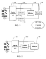
- Fig. 1 is a circuit block chart of another preferred embodiment yet of the present invention, wherein a feedback detector is provided to control the air pump driving motor.
- the preferred embodiment illustrated in Fig. 1 is essentially comprised of:
- the electric controlled unit 103 may provide the setup time difference when adapted with a deferred response function to set the response time of the electric controlled unit 103 for the duration of the receiving of feedback signal until the execution of the control of the power supplied to the air pump drive motor 102 of the air vacuum cleaner.
- the deferred response function relates to an optional function may be provided or not.
- the control by the feedback detection unit 104 for the air pump drive motor 102 of the air vacuum cleaner is described below.
- Fig. 2 is circuit block chart of the present invention showing that a feedback detector is provided to control an electric controlled unit.
- the feedback detection unit 104 is comprised of the motor speed detector 1042 and motor speed feedback signals are produced for the control of the power transported from the electric controlled unit 103 to the air pump drive motor 102 of the air vacuum cleaner.
- a normal rated voltage is inputted; and when the air vacuum cleaner is in off-load status as the cleaning tool clears away from its work area or the cleaning tool is blocked due to excessive packing against the work area so to reduce or cut off the power supplied to the air pump drive motor 102 of the air vacuum cleaner, thus to reduce the noise level and save power.
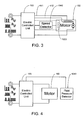
- Fig. 3 is a circuit block chart showing another preferred embodiment yet of the present invention, wherein detection signals from a motor rpm detector are operated to switch the variable windings of the air pump drive motor of the air vacuum cleaner.
- the air pump drive motor 102 may be comprised of a series excitation or compound excitation ring header type of motor. If the air pump drive motor 102 of the air vacuum cleaner relates to a series excitation ring header type of motor, and the air pump drive series excitation ring header type of motor 1021 of the air vacuum cleaner is adapted with the feedback detection unit 104 comprised of the motor speed detector 1042; then as illustrated in Fig.
- the operation control methods include: (1) the motor speed detector 1042 functioning as a switch to directly switch the control of the tapping of the series excitation magnetic filed winding from the air pump drive series excitation ring header type of motor of the air vacuum cleaner or (2) by having the motor speed detector 1042 to produce detection signals to control the operation of the electric controlled unit 103 before switching the control of the tapping of the series excitation magnetic filed winding from the air pump drive series excitation ring header type of motor of the air vacuum cleaner; so that when the air vacuum cleaner is at its normal work status, the power is supplied to a higher speed tapping 411 of the winding of magnetic field of the air pump drive series excitation ring header type of motor of the air vacuum cleaner; and when the air vacuum cleaner is in its off-load status with its cleaning tool clears away from the work area, or the cleaning tool is blocked due to excessive packing against the work area, the power is supplied to a lower speed tapping 412 of the winding of magnetic field of the air pump drive series excitation ring header type of motor of the air vacuum cleaner so to reduce the power transported
- the motor speed detector 1042 functions as a switch, or having the motor speed detector 1042 to produce detection signals to control the operation of the electric controlled unit 103 to further adjust and control the excitation intensity of the series excitation magnetic field or the parallel excitation magnetic field winding so to reduce electric energy transmitted or cut off the power supplied to the air pump drive motor 102 of the air vacuum cleaner.
- the electric controlled unit 103 may provide the setup time difference when adapted with a deferred response function to set the response time of the electric controlled unit 103 for the duration of the receiving of feedback signal until the execution of the control of the power supplied to the air pump drive motor 102 of the air vacuum cleaner.
- the deferred response function relates to an optional function may be provided or not.
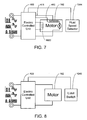
- Fig. 4 is another circuit block chart yet showing that a feedback detector is provided to control the electric controlled unit.
- the feedback detection unit 104 is comprised of a fluid pressure detector 1043 disposed at the inlet or outlet of the fluid to produce feedback signals for the control of power transported to the air pump drive motor 102 of the air vacuum cleaner from the electric controlled unit 103.
- Fig. 5 is a circuit block chart showing another preferred embodiment yet of the present invention, wherein detection signals from a fluid pressure detector of air inlet or air outlet are operated to switch an air pump drive ring header type motor variable windings of the air vacuum cleaner.
- the air pump drive motor 102 may be comprised of a series excitation or compound excitation ring header type of motor. If the air pump drive motor 102 of the air vacuum cleaner relates to a series excitation ring header type of motor and is adapted with the feedback detection unit 104 comprised of the fluid pressure detector 1043 at the inlet or outlet of the fluid; then as illustrated in Fig.
- the operation control methods include: (1) the fluid pressure detector 1043 functioning as a switch to directly switch the control of the tapping of the series excitation magnetic filed winding from the air pump drive series excitation ring header type of motor of the air vacuum cleaner or (2) by having the fluid pressure detector 1043 to produce detection signals to control the operation of the electric controlled unit 103 before switching the control of the tapping of the series excitation magnetic filed winding from the air pump drive series excitation ring header type of motor of the air vacuum cleaner; so that when the air vacuum cleaner is at its normal work status, the power is supplied to a higher speed tapping 411 of the winding of magnetic field of the air pump drive series excitation ring header type of motor of the air vacuum cleaner; and when the air vacuum cleaner is in its off-load status with its cleaning tool clears away from the work area, or the cleaning tool is blocked due to excessive packing against the work area, the power is supplied to a lower speed tapping 412 of the winding of magnetic field of the air pump drive series excitation ring header type of motor of the air vacuum cleaner so to reduce the power transported
- the fluid pressure detector 1043 functions as a switch, or having the fluid pressure detector 1043 to produce detection signals to control the operation of the electric controlled unit 103 to further adjust and control the excitation intensity of the series excitation magnetic field or the parallel excitation magnetic field winding so to reduce electric energy transmitted or cut off the power supplied to the air pump drive motor 102 of the air vacuum cleaner.
- the electric controlled unit 103 may provide the setup time difference when adapted with a deferred response function to set the response time of the electric controlled unit 103 for the duration of the receiving of feedback signal until the execution of the control of the power supplied to the air pump drive motor 102 of the air vacuum cleaner.
- the deferred response function relates to an optional function may be provided or not.
- Fig. 6 is another circuit block chart yet showing that a feedback detector is provided to control the electric controlled unit.
- the feedback detection unit 104 is comprised of the fluid speed detector 1044 to produce feedback signals for the control of the power transported to the air pump drive motor 102 of the air vacuum cleaner from the electric controlled unit 103.
- a normal rated voltage is inputted; and when the air vacuum cleaner is in off-load status as the cleaning tool clears away from its work area and the cleaning tool is blocked due to excessive packing against the work area so to reduce or cut off the power supplied to the air pump drive motor 102 of the air vacuum cleaner, thus to reduce the noise level and save power.
- Fig. 7 is a circuit block chart showing another preferred embodiment yet of the present invention, wherein detection signals from a fluid speed detector of air inlet or air outlet are operated to switch an air pump drive series excitation ring header type motor variable windings of the air vacuum cleaner. If the air pump drive motor 102 of the air vacuum cleaner relates to a series excitation ring header type of motor and is adapted with the feedback detection unit 104 comprised of the fluid pressure detector 1043 at the inlet or outlet of the fluid; then as illustrated in Fig.
- the operation control methods include: (1) the fluid speed detector 1044 functioning as a switch to directly switch the control of the tapping of the series excitation magnetic filed winding from the air pump drive series excitation ring header type of motor of the air vacuum cleaner or (2) by having the fluid speed detector 1044 to produce detection signals to control the operation of the electric controlled unit 103 before switching the control of the tapping of the series excitation magnetic filed winding from the air pump drive series excitation ring header type of motor of the air vacuum cleaner; so that when the air vacuum cleaner is at its normal work status, the power is supplied to a higher speed tapping 411 of the winding of magnetic field of the air pump drive series excitation ring header type of motor of the air vacuum cleaner; and when the air vacuum cleaner is in its off-load status with its cleaning tool clears away from the work area, or the cleaning tool is blocked due to excessive packing against the work area, the power is supplied to a lower speed tapping 412 of the winding of magnetic field of the air pump drive series excitation ring header type of motor of the air vacuum cleaner so to reduce the power transported
- the fluid speed detector 1044 functions as a switch, or having the fluid speed detector 1044 to produce detection signals to control the operation of the electric controlled unit 103 to further adjust and control the excitation intensity of the series excitation magnetic field or the parallel excitation magnetic field winding so to reduce electric energy transmitted or cut off the power supplied to the air pump drive motor 102 of the air vacuum cleaner.
- the electric controlled unit 103 may provide the setup time difference when adapted with a deferred response function to set the response time of the electric controlled unit 103 for the duration of the receiving of feedback signal until the execution of the control of the power supplied to the air pump drive motor 102 of the air vacuum cleaner.
- the deferred response function relates to an optional function may be provided or not.
- a work status detection switch e.g., a slide dynamo-electric switch 1045 or a non-slide approximate switch 1046 is further disposed at where between the fluid suction inlet of the air vacuum cleaner and its work area, the low noise and energy saving air vacuum cleaner of the present invention to control the voltage transported to the air pump driver motor 102 from the electric controlled unit 103.
- the normal rated voltage is inputted to drive the air pump drive motor 102 of the air vacuum cleaner; and when the air vacuum cleaner is in its off-load status with the cleaning tool clears away from the work area, the power transported to the air pump drive motor 102 of the air vacuum cleaner is reduced or cut off for reducing noise level and for energy-saving purposes; or the direct switch is executed by the work status detection switch to lower the speed of the air pump drive motor 102 of the air vacuum cleaner, or to cut off the power transported to the air pump drive motor 102 of the air vacuum cleaner; or the switch is executed by the electric controlled unit 103 to lower the speed of the air pump drive motor 102 of the air vacuum cleaner, or to cut off the power transported to the air pump drive motor 102 of the air vacuum cleaner.
- the electric controlled unit 103 may provide the setup time difference when adapted with a deferred response function to set the response time of the electric controlled unit 103 for the duration of the receiving of feedback signal until the execution of the control of the power supplied to the air pump drive motor 102 of the air vacuum cleaner.
- the deferred response function relates to an optional function may be provided or not.
- the fashion of the control of the operation of the air pump drive motor of the air vacuum cleaner by the work status detection switch includes:
- Fig. 13 is a circuit block chart showing that a load amperage feedback detector is provided to control the electric controlled unit.
- the feedback detection unit 104 is comprised of the motor load amperage feedback detector 1041 and the load amperage feedback signals are provided for the control of the power transported from the electric controlled unit 103 to the air pump drive motor 102 of the air vacuum cleaner.
- the electric controlled unit 103 When the air vacuum is in its normal work status, a normal rated voltage is inputted; and when the air vacuum cleaner is in off-load status as the cleaning tool clears away from its work area or the cleaning tool is blocked due to excessive packing against the work area, the electric controlled unit 103 is operated to reduce or cut off the power supplied to the air pump drive motor 102 of the air vacuum cleaner, thus to reduce the noise level and save power.
- the low noise and energy saving air vacuum cleaner adjusted and controlled according to load of the present invention may operate by comparing the detection amperage of the motor load amperage feedback detector 1041 and the setting of the amperage control device so to input the rated voltage of normal status when the air vacuum cleaner is in normal work status; and the increased amperage exceeds the setting due to that the air vacuum cleaner is in off-load status as the cleaning tool clears away from its work area or the cleaning tool is blocked due to excessive packing against the work area, the electric controlled unit 103 is operated to reduce electric energy transmitted or cut off the power supplied to the air pump drive motor 102 of the air vacuum cleaner for lowering noise level and saving energy.
- the electric controlled unit 103 may provide the setup time difference when adapted with a deferred response function to set the response time of the electric controlled unit 103 for the duration of the receiving of feedback signal until the execution of the control of the power supplied to the air pump drive motor 102 of the air vacuum cleaner.
- the deferred response function relates to an optional function may be provided or not.
- a low noise and energy saving air vacuum cleaner that is capable of adjusting and controlling electric energy of the present invention achieves reduced noise level and energy saving purposes by reducing the power transported to the air pump driver motor of the air vacuum cleaner when it is in a off-load status and its cleaning tool clears away from its work area or the cleaning tool is blocked due to excessive packing against the work area by providing an active control unit, a passive control unit and a feedback detection unit at where between the input source and the air pump drive motor of the air vacuum cleaner.
Landscapes
- Engineering & Computer Science (AREA)
- Mechanical Engineering (AREA)
- Control Of Electric Motors In General (AREA)
- Electric Vacuum Cleaner (AREA)
- Air Conditioning Control Device (AREA)
- Control Of Ac Motors In General (AREA)
- Control Of Positive-Displacement Pumps (AREA)
Applications Claiming Priority (1)
| Application Number | Priority Date | Filing Date | Title |
|---|---|---|---|
| TW096104676A TW200833287A (en) | 2007-02-07 | 2007-02-07 | A low noise and energy saving air vacuum cleaner |
Publications (1)
| Publication Number | Publication Date |
|---|---|
| EP2103243A1 true EP2103243A1 (de) | 2009-09-23 |
Family
ID=45789195
Family Applications (1)
| Application Number | Title | Priority Date | Filing Date |
|---|---|---|---|
| EP08250936A Withdrawn EP2103243A1 (de) | 2007-02-07 | 2008-03-18 | Geräuscharmer und energiesparender Staubsauger |
Country Status (5)
| Country | Link |
|---|---|
| US (2) | US20080034532A1 (de) |
| EP (1) | EP2103243A1 (de) |
| JP (1) | JP2008220812A (de) |
| CN (1) | CN101243957A (de) |
| TW (1) | TW200833287A (de) |
Cited By (4)
| Publication number | Priority date | Publication date | Assignee | Title |
|---|---|---|---|---|
| GB2479987A (en) * | 2010-04-30 | 2011-11-02 | Oreck Holdings Llc | Vacuum cleaner blockage detection system and method |
| DE102012102631A1 (de) | 2012-03-27 | 2013-10-02 | Alfred Kärcher Gmbh & Co. Kg | Verfahren zum Einstellen eines Saugsystems, Verfahren zum Betreiben eines Saugsystems und Saugsystem |
| CN104970738A (zh) * | 2015-07-31 | 2015-10-14 | 苏州蓝王机床工具科技有限公司 | 一种电源自学习吸尘器 |
| CN105437962A (zh) * | 2014-09-26 | 2016-03-30 | 比亚迪股份有限公司 | 混合动力汽车及其能量回馈控制方法和动力传动系统 |
Families Citing this family (29)
| Publication number | Priority date | Publication date | Assignee | Title |
|---|---|---|---|---|
| KR101612659B1 (ko) * | 2009-04-30 | 2016-04-15 | 악티에볼라겟 엘렉트로룩스 | 진공청소기와 전기모터를 제어하기 위한 방법 |
| TWI403300B (zh) * | 2009-11-16 | 2013-08-01 | Ind Tech Res Inst | 清潔裝置之控制方法 |
| GB201006388D0 (en) | 2010-04-16 | 2010-06-02 | Dyson Technology Ltd | Control of brushless motor |
| GB201006397D0 (en) | 2010-04-16 | 2010-06-02 | Dyson Technology Ltd | Control of a brushless motor |
| GB201006395D0 (en) | 2010-04-16 | 2010-06-02 | Dyson Technology Ltd | Control of a brushless motor |
| GB201006387D0 (en) * | 2010-04-16 | 2010-06-02 | Dyson Technology Ltd | Control of a brushless motor |
| GB201006396D0 (en) | 2010-04-16 | 2010-06-02 | Dyson Technology Ltd | Control of a brushless motor |
| GB201006398D0 (en) | 2010-04-16 | 2010-06-02 | Dyson Technology Ltd | Control of a brushless motor |
| GB201006386D0 (en) | 2010-04-16 | 2010-06-02 | Dyson Technology Ltd | Control of a brushless motor |
| GB201006391D0 (en) | 2010-04-16 | 2010-06-02 | Dyson Technology Ltd | Control of a brushless permanent-magnet motor |
| GB201006384D0 (en) * | 2010-04-16 | 2010-06-02 | Dyson Technology Ltd | Control of a brushless motor |
| GB201006392D0 (en) | 2010-04-16 | 2010-06-02 | Dyson Technology Ltd | Controller for a brushless motor |
| GB201006390D0 (en) | 2010-04-16 | 2010-06-02 | Dyson Technology Ltd | Control of a brushless motor |
| JP4920779B2 (ja) * | 2010-09-15 | 2012-04-18 | シャープ株式会社 | 電気掃除機 |
| GB2484289B (en) | 2010-10-04 | 2013-11-20 | Dyson Technology Ltd | Control of an electrical machine |
| JP2012179528A (ja) * | 2011-02-28 | 2012-09-20 | Hitachi Plant Technologies Ltd | 電気集塵装置用の電源制御装置及びこれを備えた電気集塵装置 |
| CN102278094A (zh) * | 2011-07-02 | 2011-12-14 | 常州联科电气成套设备有限公司 | 抽油机节能装置 |
| KR102139167B1 (ko) | 2014-03-18 | 2020-07-29 | 삼성전자주식회사 | 청소기 및 그 제어방법 |
| CN108400629B (zh) * | 2014-05-18 | 2023-01-24 | 百得有限公司 | 电池组 |
| CN105662268B (zh) * | 2014-11-20 | 2021-03-05 | 江苏美的清洁电器股份有限公司 | 吸尘器 |
| CN107370322B (zh) * | 2017-08-24 | 2021-12-07 | 莱克电气股份有限公司 | 一种吸尘器电机及吸尘器 |
| CN107516990B (zh) * | 2017-08-24 | 2021-09-14 | 莱克电气股份有限公司 | 一种吸尘器电机及吸尘器 |
| JP7123690B2 (ja) * | 2018-08-08 | 2022-08-23 | 東芝ライフスタイル株式会社 | 電気掃除機 |
| CN110870661B (zh) * | 2018-08-31 | 2021-11-19 | 佛山市顺德区美的电热电器制造有限公司 | 风机的运行控制方法、装置、风机、烹饪器具和存储介质 |
| CN114999487B (zh) * | 2019-11-29 | 2025-03-11 | 添可智能科技有限公司 | 清洁设备的语音交互方法及清洁设备 |
| CN114617496B (zh) * | 2021-07-20 | 2023-08-04 | 尚科宁家(中国)科技有限公司 | 一种低噪音表面清洁机 |
| CN113813069A (zh) * | 2021-08-31 | 2021-12-21 | 深圳市宝丰通电器制造有限公司 | 冲牙器及冲牙器流体控制方法 |
| WO2023224229A1 (ko) * | 2022-05-16 | 2023-11-23 | 삼성전자주식회사 | 진공 청소기 및 그 제어 방법 |
| CN117297406A (zh) * | 2022-06-22 | 2023-12-29 | 浙江齐享科技有限公司 | 一种自清洁系统、洗地机及工作方法 |
Citations (5)
| Publication number | Priority date | Publication date | Assignee | Title |
|---|---|---|---|---|
| DE3248217A1 (de) * | 1982-12-27 | 1984-06-28 | Gerhard 7262 Althengstett Kurz | Vorrichtung zur temperaturabhaengigen elektromotor-steuerung |
| EP0320878A2 (de) * | 1987-12-15 | 1989-06-21 | Hitachi, Ltd. | Verfahren für den Betrieb eines Staubsaugers |
| EP0423670A1 (de) * | 1989-10-18 | 1991-04-24 | Hitachi, Ltd. | Staubsauger und Verfahren zum Regeln desselben |
| US5072484A (en) * | 1989-02-14 | 1991-12-17 | Aktiebolaget Electrolux | Vaccum cleaner suction control |
| EP0581557A1 (de) * | 1992-07-30 | 1994-02-02 | Tai-Her Yang | Regelschaltung für einen Gleichstrommotor mit einer mehrfach angezapften, in Serie liegenden Feldwicklung |
Family Cites Families (6)
| Publication number | Priority date | Publication date | Assignee | Title |
|---|---|---|---|---|
| FR2708188A1 (fr) * | 1993-07-28 | 1995-02-03 | Philips Laboratoire Electroniq | Aspirateur avec des moyens de détection des sols et de réglage de la puissance du moteur en fonction du sol détecté. |
| US5835676A (en) * | 1994-04-06 | 1998-11-10 | Brother Kogyo Kabushiki Kaisha | Motor driving apparatus |
| US5567127A (en) * | 1994-11-09 | 1996-10-22 | Wentz; Kennith W. | Low noise air blower |
| US6457205B1 (en) * | 2000-05-24 | 2002-10-01 | Fantom Technologies Inc. | Vacuum cleaner having a plurality of power modes |
| JP2002345288A (ja) * | 2001-05-15 | 2002-11-29 | Toshiba Tec Corp | 三相ブラシレス電動機の起動方法、その駆動制御回路、電動送風機及び電気掃除機 |
| TW579289B (en) * | 2001-05-23 | 2004-03-11 | Toshiba Tec Kk | Vacuum cleaner |
-
2006
- 2006-08-11 US US11/502,529 patent/US20080034532A1/en not_active Abandoned
-
2007
- 2007-01-30 US US11/699,385 patent/US20080180049A1/en not_active Abandoned
- 2007-02-07 TW TW096104676A patent/TW200833287A/zh unknown
- 2007-02-13 CN CNA2007100791205A patent/CN101243957A/zh active Pending
- 2007-03-15 JP JP2007066465A patent/JP2008220812A/ja active Pending
-
2008
- 2008-03-18 EP EP08250936A patent/EP2103243A1/de not_active Withdrawn
Patent Citations (5)
| Publication number | Priority date | Publication date | Assignee | Title |
|---|---|---|---|---|
| DE3248217A1 (de) * | 1982-12-27 | 1984-06-28 | Gerhard 7262 Althengstett Kurz | Vorrichtung zur temperaturabhaengigen elektromotor-steuerung |
| EP0320878A2 (de) * | 1987-12-15 | 1989-06-21 | Hitachi, Ltd. | Verfahren für den Betrieb eines Staubsaugers |
| US5072484A (en) * | 1989-02-14 | 1991-12-17 | Aktiebolaget Electrolux | Vaccum cleaner suction control |
| EP0423670A1 (de) * | 1989-10-18 | 1991-04-24 | Hitachi, Ltd. | Staubsauger und Verfahren zum Regeln desselben |
| EP0581557A1 (de) * | 1992-07-30 | 1994-02-02 | Tai-Her Yang | Regelschaltung für einen Gleichstrommotor mit einer mehrfach angezapften, in Serie liegenden Feldwicklung |
Cited By (7)
| Publication number | Priority date | Publication date | Assignee | Title |
|---|---|---|---|---|
| GB2479987A (en) * | 2010-04-30 | 2011-11-02 | Oreck Holdings Llc | Vacuum cleaner blockage detection system and method |
| GB2479987B (en) * | 2010-04-30 | 2015-03-11 | Oreck Holdings Llc | Method and system of detecting a blockage in a vacuum cleaner |
| DE102012102631A1 (de) | 2012-03-27 | 2013-10-02 | Alfred Kärcher Gmbh & Co. Kg | Verfahren zum Einstellen eines Saugsystems, Verfahren zum Betreiben eines Saugsystems und Saugsystem |
| WO2013144149A1 (de) | 2012-03-27 | 2013-10-03 | Alfred Kärcher Gmbh & Co. Kg | Verfahren zum einstellen eines saugsystems, verfahren zum betreiben eines saugsystems und saugsystem |
| CN105437962A (zh) * | 2014-09-26 | 2016-03-30 | 比亚迪股份有限公司 | 混合动力汽车及其能量回馈控制方法和动力传动系统 |
| CN105437962B (zh) * | 2014-09-26 | 2018-09-11 | 比亚迪股份有限公司 | 混合动力汽车及其能量回馈控制方法和动力传动系统 |
| CN104970738A (zh) * | 2015-07-31 | 2015-10-14 | 苏州蓝王机床工具科技有限公司 | 一种电源自学习吸尘器 |
Also Published As
| Publication number | Publication date |
|---|---|
| TW200833287A (en) | 2008-08-16 |
| US20080180049A1 (en) | 2008-07-31 |
| US20080034532A1 (en) | 2008-02-14 |
| CN101243957A (zh) | 2008-08-20 |
| JP2008220812A (ja) | 2008-09-25 |
Similar Documents
| Publication | Publication Date | Title |
|---|---|---|
| EP2103243A1 (de) | Geräuscharmer und energiesparender Staubsauger | |
| KR101340170B1 (ko) | 청소기 및 그 구동 방법 | |
| US9585533B2 (en) | Vacuum cleaner and method for cleaning a filter | |
| CN109873578B (zh) | 电动工具及电动工具的控制方法 | |
| KR101341234B1 (ko) | 청소기 및 그 구동 방법 | |
| US8232755B2 (en) | Motor with circuits for protecting motor from input power outages or surges | |
| US11541497B2 (en) | Combined electric tool coordination system and method | |
| EP3653094A1 (de) | Steuersystem eines staubsaugermotors, staubsauger und steuerverfahren | |
| CN108011559B (zh) | 电动工具及电动工具的控制方法 | |
| CN202121398U (zh) | 设有并励绕组的串励电机 | |
| CN105450144A (zh) | 吸尘器及其控制电路 | |
| KR20200039348A (ko) | 청소기 및 그것의 제어방법 | |
| CN109171558B (zh) | 吸尘器和吸尘器电机控制系统、方法 | |
| JP4927521B2 (ja) | 電気掃除機 | |
| CN105515493A (zh) | 电镐用开关磁阻调速电机控制器 | |
| JP2003093298A (ja) | 電気掃除機 | |
| EP3306807A1 (de) | Steuerungsvorrichtung für bürstenlosen gleichstrommotor | |
| CN202652143U (zh) | 一种吊扇电机的变频控制回路 | |
| JP2007319581A (ja) | 電気掃除機の制御装置 | |
| CN112087179B (zh) | 用于防止单相交流电机低速停转的驱动控制电路 | |
| JP3767472B2 (ja) | モータ制御装置及びそれを用いた電気掃除機 | |
| JP3552396B2 (ja) | ブラシレスdcモータの制御駆動装置 | |
| JP2006167239A (ja) | 電気掃除機 | |
| JP2004229995A (ja) | 電気掃除機 | |
| CN203554346U (zh) | 一种高压直流无刷风扇控制电路 |
Legal Events
| Date | Code | Title | Description |
|---|---|---|---|
| PUAI | Public reference made under article 153(3) epc to a published international application that has entered the european phase |
Free format text: ORIGINAL CODE: 0009012 |
|
| AK | Designated contracting states |
Kind code of ref document: A1 Designated state(s): AT BE BG CH CY CZ DE DK EE ES FI FR GB GR HR HU IE IS IT LI LT LU LV MC MT NL NO PL PT RO SE SI SK TR |
|
| AX | Request for extension of the european patent |
Extension state: AL BA MK RS |
|
| AKX | Designation fees paid | ||
| REG | Reference to a national code |
Ref country code: DE Ref legal event code: 8566 |
|
| STAA | Information on the status of an ep patent application or granted ep patent |
Free format text: STATUS: THE APPLICATION IS DEEMED TO BE WITHDRAWN |
|
| 18D | Application deemed to be withdrawn |
Effective date: 20100324 |