EP2103458A1 - Attelage de véhicule - Google Patents
Attelage de véhicule Download PDFInfo
- Publication number
- EP2103458A1 EP2103458A1 EP09250752A EP09250752A EP2103458A1 EP 2103458 A1 EP2103458 A1 EP 2103458A1 EP 09250752 A EP09250752 A EP 09250752A EP 09250752 A EP09250752 A EP 09250752A EP 2103458 A1 EP2103458 A1 EP 2103458A1
- Authority
- EP
- European Patent Office
- Prior art keywords
- draw bar
- guide
- mounting frame
- vehicle hitch
- vehicle
- Prior art date
- Legal status (The legal status is an assumption and is not a legal conclusion. Google has not performed a legal analysis and makes no representation as to the accuracy of the status listed.)
- Granted
Links
Images


Classifications
-
- B—PERFORMING OPERATIONS; TRANSPORTING
- B60—VEHICLES IN GENERAL
- B60D—VEHICLE CONNECTIONS
- B60D1/00—Traction couplings; Hitches; Draw-gear; Towing devices
- B60D1/24—Traction couplings; Hitches; Draw-gear; Towing devices characterised by arrangements for particular functions
- B60D1/42—Traction couplings; Hitches; Draw-gear; Towing devices characterised by arrangements for particular functions for being adjustable
- B60D1/46—Traction couplings; Hitches; Draw-gear; Towing devices characterised by arrangements for particular functions for being adjustable vertically
- B60D1/465—Traction couplings; Hitches; Draw-gear; Towing devices characterised by arrangements for particular functions for being adjustable vertically comprising a lifting mechanism, e.g. for coupling while lifting
-
- A—HUMAN NECESSITIES
- A01—AGRICULTURE; FORESTRY; ANIMAL HUSBANDRY; HUNTING; TRAPPING; FISHING
- A01B—SOIL WORKING IN AGRICULTURE OR FORESTRY; PARTS, DETAILS, OR ACCESSORIES OF AGRICULTURAL MACHINES OR IMPLEMENTS, IN GENERAL
- A01B59/00—Devices specially adapted for connection between animals or tractors and agricultural machines or implements
- A01B59/04—Devices specially adapted for connection between animals or tractors and agricultural machines or implements for machines pulled or pushed by a tractor
- A01B59/042—Devices specially adapted for connection between animals or tractors and agricultural machines or implements for machines pulled or pushed by a tractor having pulling means arranged on the rear part of the tractor
-
- B—PERFORMING OPERATIONS; TRANSPORTING
- B60—VEHICLES IN GENERAL
- B60D—VEHICLE CONNECTIONS
- B60D1/00—Traction couplings; Hitches; Draw-gear; Towing devices
- B60D1/24—Traction couplings; Hitches; Draw-gear; Towing devices characterised by arrangements for particular functions
- B60D1/36—Traction couplings; Hitches; Draw-gear; Towing devices characterised by arrangements for particular functions for facilitating connection, e.g. hitch catchers
Definitions
- the present invention relates to a vehicle hitch, in particular a pick-up hitch for a vehicle such as, for example, an agricultural or construction vehicle.
- vehicle hitch is the so-called pick-up hitch, which incorporates a moveable draw bar having a pin hitch or hook at one end for engaging the towing eye on a trailer.
- the draw bar is locked in a raised position to provide a desired ground clearance until such time as it is required to perform a hitching operation, at which point the draw bar can be 'dropped' down into a hitching position and subsequently raised to engage and 'pick up' the towing eye of the trailer.
- pick-up hitches tends to be too heavy for safe manoeuvring by hand, and so pick-up hitches generally incorporate a drive arrangement for moving the draw bar between the raised position and the hitching position.
- the draw bar is hydraulically actuated, either by a dedicated hydraulic ram or by hydraulic "drop arms" (the latter being provided as standard on the rear of many agricultural vehicles) and the path of motion of the draw bar is predetermined by a series of pivoting linkages which pivotally connect the draw bar to a mounting frame on the vehicle and operably link the draw bar to the hydraulic ram.
- GB2380720 which utilises a quadrilateral pivoting linkage to operably link a dedicated hydraulic ram to a corresponding moveable draw bar.
- the geometry of the quadrilateral linkage determines the path of movement of the draw bar.
- a vehicle hitch comprising a mounting frame for attachment to a vehicle, a draw bar having a hitching-point towards one end, and a drive unit acting between the mounting frame and the draw bar for driving the draw bar outwardly away from the vehicle and into a hitching position, the mounting frame having a sliding or rolling guide arrangement for slidably or rollably guiding the hitching-point downwardly towards the ground as the draw bar is driven outwardly into said hitching position.
- the guide arrangement may slidably or rollably support the draw bar on the mounting frame.
- the guide arrangement may comprise a pair of sliding or rolling guides in the form of a support guide for supporting the draw bar and an opposing counterbalancing guide for slidably or rollably cantilevering the draw bar on the support guide.
- one or both of the support guide and the counterbalancing guide are curved for guiding the draw bar in a downward arc towards the ground as the draw bar is driven into said hitching position.
- the support guide and the counterbalancing guide may be concentric, substantially arcuate guides.
- the draw bar may have one or more associated arcuate guide elements that slidably engage the arcuate guides.
- the drive unit is a linear drive device pivotally connected to the draw bar and further configured for pivotal connection to the mounting frame.
- the linear drive device may be directly pivotally connected to the mounting frame.
- the linear drive device may be double-acting for retracting the draw bar from the hitching position into an retracted position.
- the draw bar may comprise a pair of parallel draw arms and the linear drive device may be aligned in-between the draw arms.
- the draw bar In said retracted position at least a portion of the draw bar may be housed within the mounting frame. In said retracted position, the draw bar may be substantially housed in the mounting frame.
- the mounting frame may comprise a pair of mounting arms and the draw bar is retractable between the mounting arms.
- the support guide and counterbalancing guide may each be defined by one or more guide slots or channels on the mounting frame, the draw bar being slidably mounted in each guide slot or channel.
- One or more of the guides may comprise a load-bearing replaceable guide insert.
- the load bearing insert is preferably at a point of maximum or high load-bearing where wear of the guide may be high.
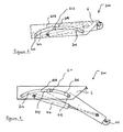
- a vehicle hitch 1 comprises a mounting frame 2, in this case a channel-shaped sub-frame (which is shown in isolation in Figures 3a and 3b ), and a draw bar 4 (which is shown in isolation in Figure 4 ).
- the mounting frame 2 is configured for attachment to a vehicle (not shown).
- the mounting frame 2 is bolted to the vehicle, for example to the underside of the rear axle housing, and may be centrally located between the rear wheels, particularly where the vehicle is a tractor.
- Figures 1 to 4 show the mounting frame 2 in the general orientation in which it would be when attached to a vehicle.
- the mounting frame 2 comprises a pair of generally parallel arms 6, 8 maintained in spaced-apart relation by a series of plates, 10, 12, 14.
- the arms 6, 8 define a channel 16 therebetween for receiving the draw bar 4 in a manner described in more detail below.
- the draw bar 4 similarly comprises a pair of parallel draw arms 18, 20 ( Figure 1 ).
- a hook 22 is attached at one end of the draw bar 4, between the draw arms 18, 20, to form a hitching point for the draw bar 4.
- Any other suitable hitching point may be used in place of the hook 22, for example a pin hitch, and the hitching point may be replaceable to allow interchange of different hitching points, as desired.
- a linear drive device in the form of a double-acting hydraulic ram 24 is connected to the draw bar 4 and the mounting frame 2 by means of pinned connections 26, 28.
- the hydraulic ram 24 acts as a drive unit between the mounting frame 2 and the draw bar 4 for driving the draw bar 4 between a raised position, shown in Figure 2 , and a hitching position, shown in Figure 1 (and also in phantom in Figure 2 ).
- the draw bar 4 is guided from the raised position to the hitching position not by a series of pivoting linkages, but by a sliding guide arrangement.
- the guide arrangement supports the draw bar 4 on the mounting frame 2 and further guides the end of the draw bar 4 having the hook 22 downwardly towards the ground as the draw bar 4 is driven outwardly by the hydraulic ram 24.
- the guide arrangement comprises a curved support guide and an opposing curved counterbalancing guide.
- the support guide is in the form of a lower pair of guide members 30a, 30b that have a curved bearing surface respectively slidably supporting corresponding curved guide elements 18a, 20a on the draw arms 18, 20 of the draw bar 4.
- the guide members 30a, 30b incorporate replaceable load-bearing guide inserts 31 at their outward end, which can be replaced when they become worn.
- the counterbalancing guide is in the form of an upper pair of guide members (of which only one member 32b can be seen in Figure 3a ) that have a curved bearing surface which slidably engage the upper surface of the curved guide elements 18a, 20a.
- the curved bearing surfaces of the guide members in the embodiment of Figures 1 to 4 are arcuate (i.e. define substantially circular arcs when viewed in Figure 3 ) and concentric.
- the guide members are fixed to the mounting frame 2 by any suitable means, or may be formed integrally with the mounting frame 2.
- the outward end of the mounting frame 2 is provided with a locking plate 36 and a pair of interconnected pivoting locking catches 38 which can be moved from a locking position to a release position by means of a conventional linkage such as a rod or cable arrangement (not shown) operable from the cabin of a vehicle (not shown).
- a conventional linkage such as a rod or cable arrangement (not shown) operable from the cabin of a vehicle (not shown).
- Corresponding locking projections 40 are formed at the outward end of the draw arms 18,20.
- the hitch 1 will typically be retained in the raised position shown in Figure 2 until such time as it is desired to perform a hitching operation.
- the draw bar 4 is retained in the raised position by means of the locking catches 38, which engage the corresponding locking projections 40 on the draw arms 18, 20. In this raised position, the draw bar is received in a retracted position in the channel 16 in the mounting frame 2.
- the draw bar 4 is substantially housed in the mounting frame i.e. the draw bar 4 does not project substantially below the mounting frame 2, thus maintaining the ground clearance between the (fixed) mounting frame 2 and the ground.
- the draw arms 18, 20 are retracted between the mounting arms 6, 8.
- the hydraulic ram 24 is aligned, or nested, in-between the draw arms 18, 20.
- the vehicle operator releases the locking catches 38 from the projections 40 and extends the hydraulic ram 24 to drive the draw bar 4 outwardly from the vehicle into the hitching position shown in Figure 1 .
- the upper guide member 32b on the mounting arm 6 and the corresponding upper guide member (not shown) on the mounting arm 8 act to slidably cantilever the draw bar 4 on the guide members 30a, 30b during movement of the draw bar 4 towards the hitching position, thus preventing pivoting or "tipping" movement of the draw bar 4 'over' the outward end 30c of the guide members 30a, 30b.
- the draw bar 4 may then be retracted by means of the hydraulic ram 24, whereby the draw bar 4 engages the towing eye of the trailer as it moves back along an upward arc (corresponding to the downward arc A) and into the raised position shown in Figure 2 .
- the locking catches 38 re-engage the locking projections 40 and the hook 22 is brought into proximity with the locking plate 36 in order to prevent the towing eye of the trailer from "jumping" off the hook 22 whilst the trailer is being towed.
- the trailer is thus securely hitched to the vehicle until such time as the locking catches 38 are released.
- the hook 22 is effectively driven both outwardly as well as downwardly, thus tending to provide the operator with increased visibility, particularly in the case where the hitch 1 is attached to the back of an agricultural vehicle such as a tractor.
- the precise downward path of the hook 22 is predetermined by the geometry of the guide arrangement, in particular the geometry of the support guide and the counterbalancing guide, which may be varied appropriately.
- a downward arc such as the downward arc A is considered to be particularly advantageous because, when the draw bar is retracted to the raised position to engage the towing eye of a trailer, the vertical component of movement of the hook 22 will be greater than the horizontal component of movement so that the hook 22 will trace a predominantly vertical path initially, promoting a clean 'pick up' of the towing eye. It should also be noted here that the centre of curvature of the guides may be below ground.
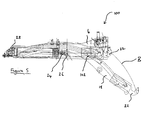
- Figure 5 shows an alternative vehicle hitch 100.
- the same reference numerals have been retained for those features already described in relation to Figures 1 to 4 .
- the arrangement shown in Figure 5 differs from the previous arrangement shown in Figures 1 to 4 in that the support guide and the counterbalancing guide are defined a pair of guide slots, rather than by separate guide members.
- a pair of arcuate slots 102 (of which only one slot is visible in Figure 5 ) is provided in the respective mounting arms 6, 8; the draw bar 4 is slidably mounted in the slots 102 by means of the arcuate guide elements 18a, 20a for sliding movement into a hitching position (shown in phantom in Figure 5 ) along a downward arc B.
- the lower edges of the slots 102 define the support guide for slidably supporting the draw bar 4 on the mounting frame 2
- the upper edges of the slots 102 define the counterbalancing guide for slidably cantilevering the draw bar on the support guide.
- the vehicle hitch 100 may be operated in essentially the same manner as the vehicle hitch 1 and the geometry of the guide slots 102 be varied as appropriate to alter the (predetermined) downward arc B.
- Figures 6 and 7 show a yet further alternative vehicle hitch 200, wherein the support guide and counterbalancing guide are each defined by guide slots in similar manner to the guide slots 102, but the guide slots are not arcuate.
- the support guide and the counterbalancing guide are defined by the lower and upper edges of a pair of guide slots 202 each incorporating a first upwardly curving section 204, a downwardly curving section 206 and a generally linear section 208 in between the curved sections 204, 206.
- the draw bar 4 is provided with associated first and second pairs of guide elements 210, 212 (only one member of each pair of guide elements 210, 212 can be seen in Figures 6 and 7 ) which are slidably received in the respective guide slots 202 for guiding the hook 22 downwardly as the draw bar 4 is driven outwardly into the hitching position.
- the specific geometry of the guide slots 202 and guide elements 210, 212 may vary.
- the support guide and counterbalancing guide might be defined by any number of guide slots with the draw bar being slidably mounted in each slot and the slots together slidably guiding the draw bar downwardly towards the ground as the draw bar is driven outwardly into said hitching position.
- One or more of the guide slots may be linear.
- the guides may be defined by one or more channels in the mounting frame, rather than by guide slots.
- the guide arrangement might equally be a rollable guide arrangement for rollalby guiding the hitching point.
- the guides may comprise one or more rollers, or the guiding elements associated with the draw bar may comprise rollers.
- any suitable length may be employed for the counterbalancing guide and the support guide in a given application.
- the counterbalancing guide it will be appreciated that as the draw bar is progressively cantilevered towards the hitching position, the "cantilever point" of maximum bearing load on the counterbalancing guide will move with the draw bar, and therefore the length of the counterbalancing guide will generally be dependent upon the degree of movement of the draw bar between the raised position and the hitching position.
- the vehicle hitch is powered by a double acting hydraulic ram.
- a single acting hydraulic ram may be appropriate.
- the ram would be retracted under power, but might extend under the weight of the draw bar and whatever was attached to the draw bar at the time.
- the single hydraulic ram could be replaced by more than one hydraulic ram, or by any other suitable power source.
- hydraulic ram 24 is directly pivotally connected to the mounting frame 2 and the draw bar 4
- the hydraulic ram may be pivotally connected to the draw bar and some other part of the vehicle such as the vehicle chassis.
- the hydraulic ram would still operate in the same way as in the illustrated embodiments and would still effectively be acting between the mounting frame and the draw bar.
- a vehicle hitch in accordance with the present invention can be fitted to any part of a vehicle and could for example be fitted to the front of the vehicle or could even be adapted for fitting to a non-horizontal surface at the rear of a vehicle with appropriate adjustment of the geometry of its components.
- a sliding or rolling guide arrangement in accordance with the present invention is preferable to existing arrangements which guide the draw bar using relatively complicated pivoting linkages, and in particular that the number of manufacturing parts may be significantly reduced.
Landscapes
- Engineering & Computer Science (AREA)
- Mechanical Engineering (AREA)
- Transportation (AREA)
- Life Sciences & Earth Sciences (AREA)
- Zoology (AREA)
- Soil Sciences (AREA)
- Environmental Sciences (AREA)
- Agricultural Machines (AREA)
- Catching Or Destruction (AREA)
Applications Claiming Priority (1)
| Application Number | Priority Date | Filing Date | Title |
|---|---|---|---|
| GB0805064A GB2458478A (en) | 2008-03-18 | 2008-03-18 | Agricultural tractor hitch |
Publications (2)
| Publication Number | Publication Date |
|---|---|
| EP2103458A1 true EP2103458A1 (fr) | 2009-09-23 |
| EP2103458B1 EP2103458B1 (fr) | 2011-09-21 |
Family
ID=39356712
Family Applications (1)
| Application Number | Title | Priority Date | Filing Date |
|---|---|---|---|
| EP09250752A Active EP2103458B1 (fr) | 2008-03-18 | 2009-03-18 | Attelage de véhicule |
Country Status (3)
| Country | Link |
|---|---|
| EP (1) | EP2103458B1 (fr) |
| AT (1) | ATE525223T1 (fr) |
| GB (1) | GB2458478A (fr) |
Cited By (3)
| Publication number | Priority date | Publication date | Assignee | Title |
|---|---|---|---|---|
| IT201800011187A1 (it) * | 2018-12-17 | 2020-06-17 | Cbm Spa | Dispositivo di traino per un veicolo agricolo o industriale |
| IT201800011189A1 (it) * | 2018-12-17 | 2020-06-17 | Cbm Spa | Dispositivo di traino per un veicolo agricolo o industriale |
| SE2550700A1 (en) * | 2024-07-19 | 2026-01-20 | Bamford Excavators Ltd | A Tow Hitch for a Working Vehicle |
Families Citing this family (8)
| Publication number | Priority date | Publication date | Assignee | Title |
|---|---|---|---|---|
| IES20080802A2 (en) * | 2008-10-03 | 2010-05-12 | Mccormick Patrick | An improved hitch |
| EP3379222B1 (fr) | 2017-03-22 | 2020-12-30 | Methode Electronics Malta Ltd. | Ensemble de capteur à base magnétoélastique |
| US11135882B2 (en) | 2018-02-27 | 2021-10-05 | Methode Electronics, Inc. | Towing systems and methods using magnetic field sensing |
| US11221262B2 (en) | 2018-02-27 | 2022-01-11 | Methode Electronics, Inc. | Towing systems and methods using magnetic field sensing |
| US10670479B2 (en) | 2018-02-27 | 2020-06-02 | Methode Electronics, Inc. | Towing systems and methods using magnetic field sensing |
| US11084342B2 (en) | 2018-02-27 | 2021-08-10 | Methode Electronics, Inc. | Towing systems and methods using magnetic field sensing |
| US11491832B2 (en) | 2018-02-27 | 2022-11-08 | Methode Electronics, Inc. | Towing systems and methods using magnetic field sensing |
| US12017489B2 (en) * | 2022-09-01 | 2024-06-25 | New Heights, Llc | Trailer tongue system |
Citations (6)
| Publication number | Priority date | Publication date | Assignee | Title |
|---|---|---|---|---|
| US1902212A (en) | 1931-10-20 | 1933-03-21 | Bonge Fred | Towing device |
| US2269023A (en) * | 1938-09-14 | 1942-01-06 | Case Co J I | Tractor hitch |
| AU446361B2 (en) | 1970-02-27 | 1974-03-04 | Massey-Ferguson (Australia) Ltd | Improved hitch |
| EP0728600A1 (fr) | 1995-02-24 | 1996-08-28 | Frans Pateer Bv | Dispositif à crochet relevable pour le tractage de véhicules |
| FR2749803A1 (fr) * | 1996-06-17 | 1997-12-19 | Cochet | Remorque pour le transport d'engins lourds et encombrants |
| GB2380720A (en) | 2001-10-08 | 2003-04-16 | Bill Bennett Engineering Ltd | Vehicle hitch |
Family Cites Families (1)
| Publication number | Priority date | Publication date | Assignee | Title |
|---|---|---|---|---|
| US4542913A (en) * | 1984-07-26 | 1985-09-24 | Deere & Company | Pick-up type drawbar assembly |
-
2008
- 2008-03-18 GB GB0805064A patent/GB2458478A/en not_active Withdrawn
-
2009
- 2009-03-18 EP EP09250752A patent/EP2103458B1/fr active Active
- 2009-03-18 AT AT09250752T patent/ATE525223T1/de active
Patent Citations (6)
| Publication number | Priority date | Publication date | Assignee | Title |
|---|---|---|---|---|
| US1902212A (en) | 1931-10-20 | 1933-03-21 | Bonge Fred | Towing device |
| US2269023A (en) * | 1938-09-14 | 1942-01-06 | Case Co J I | Tractor hitch |
| AU446361B2 (en) | 1970-02-27 | 1974-03-04 | Massey-Ferguson (Australia) Ltd | Improved hitch |
| EP0728600A1 (fr) | 1995-02-24 | 1996-08-28 | Frans Pateer Bv | Dispositif à crochet relevable pour le tractage de véhicules |
| FR2749803A1 (fr) * | 1996-06-17 | 1997-12-19 | Cochet | Remorque pour le transport d'engins lourds et encombrants |
| GB2380720A (en) | 2001-10-08 | 2003-04-16 | Bill Bennett Engineering Ltd | Vehicle hitch |
Cited By (5)
| Publication number | Priority date | Publication date | Assignee | Title |
|---|---|---|---|---|
| IT201800011187A1 (it) * | 2018-12-17 | 2020-06-17 | Cbm Spa | Dispositivo di traino per un veicolo agricolo o industriale |
| IT201800011189A1 (it) * | 2018-12-17 | 2020-06-17 | Cbm Spa | Dispositivo di traino per un veicolo agricolo o industriale |
| EP3670215A1 (fr) * | 2018-12-17 | 2020-06-24 | Cbm - S.P.A. | Dispositif d'attelage pour un véhicule agricole ou industriel |
| EP3669623A1 (fr) * | 2018-12-17 | 2020-06-24 | Cbm - S.P.A. | Dispositif de remorquage pour un véhicule agricole ou industriel |
| SE2550700A1 (en) * | 2024-07-19 | 2026-01-20 | Bamford Excavators Ltd | A Tow Hitch for a Working Vehicle |
Also Published As
| Publication number | Publication date |
|---|---|
| EP2103458B1 (fr) | 2011-09-21 |
| GB0805064D0 (en) | 2008-04-23 |
| ATE525223T1 (de) | 2011-10-15 |
| GB2458478A (en) | 2009-09-23 |
Similar Documents
| Publication | Publication Date | Title |
|---|---|---|
| EP2103458B1 (fr) | Attelage de véhicule | |
| US4470211A (en) | Thrust coupling for a vehicle | |
| US8141929B2 (en) | Power operated retractable tailgate assembly | |
| US7607711B2 (en) | Power operated retractable tailgate assembly | |
| US5692573A (en) | Towing Arrangement | |
| CA2816506A1 (fr) | Appareil de remorquage ajustable pour vehicules | |
| CA2881268A1 (fr) | Composant d'articulation d'un ensemble de fond de trou, ensemble de guidage de fond de trou, et procede pour faire fonctionner un outil de fond de trou | |
| US20080265544A1 (en) | Fifth Wheel Assembly for Coupling a Trailer to a Truck Tractor and a Method for Operating Said Assembly | |
| US4815915A (en) | Under-vehicle towing apparatus | |
| CA2717122C (fr) | Attelage coulissant | |
| EP0138519A2 (fr) | Dispositifs d'attelage | |
| US6405806B1 (en) | Vehicle implement interface | |
| US7937858B2 (en) | Hitch assembly and tractor scraper using same | |
| CA2626321A1 (fr) | Remorque et ensemble de roues mobiles combines | |
| GB2380720A (en) | Vehicle hitch | |
| EP0128807A1 (fr) | Dispositif pour le soulèvement et le remorquage d'un véhicule | |
| EP0040542B1 (fr) | Remorque à col de cygne repliable | |
| AU2015200566B2 (en) | Gooseneck towing module and method of use | |
| DE102006039672B4 (de) | Lade- und/oder Häckselwagen | |
| DE102012015556B4 (de) | Sattelauflieger mit einer Kippermulde | |
| AU647311B2 (en) | Vehicle hitch assembly | |
| US5713714A (en) | Tilt cylinder for an underreach assembly | |
| IES20080802A2 (en) | An improved hitch | |
| EP1277690A1 (fr) | Dispositif pour enlever un véhicule endommagé ou mal stationné | |
| EP1837232A2 (fr) | Remorques |
Legal Events
| Date | Code | Title | Description |
|---|---|---|---|
| PUAI | Public reference made under article 153(3) epc to a published international application that has entered the european phase |
Free format text: ORIGINAL CODE: 0009012 |
|
| AK | Designated contracting states |
Kind code of ref document: A1 Designated state(s): AT BE BG CH CY CZ DE DK EE ES FI FR GB GR HR HU IE IS IT LI LT LU LV MC MK MT NL NO PL PT RO SE SI SK TR |
|
| AX | Request for extension of the european patent |
Extension state: AL BA RS |
|
| 17P | Request for examination filed |
Effective date: 20100322 |
|
| 17Q | First examination report despatched |
Effective date: 20100415 |
|
| AKX | Designation fees paid |
Designated state(s): AT BE BG CH CY CZ DE DK EE ES FI FR GB GR HR HU IE IS IT LI LT LU LV MC MK MT NL NO PL PT RO SE SI SK TR |
|
| GRAP | Despatch of communication of intention to grant a patent |
Free format text: ORIGINAL CODE: EPIDOSNIGR1 |
|
| GRAS | Grant fee paid |
Free format text: ORIGINAL CODE: EPIDOSNIGR3 |
|
| GRAA | (expected) grant |
Free format text: ORIGINAL CODE: 0009210 |
|
| AK | Designated contracting states |
Kind code of ref document: B1 Designated state(s): AT BE BG CH CY CZ DE DK EE ES FI FR GB GR HR HU IE IS IT LI LT LU LV MC MK MT NL NO PL PT RO SE SI SK TR |
|
| REG | Reference to a national code |
Ref country code: GB Ref legal event code: FG4D |
|
| REG | Reference to a national code |
Ref country code: CH Ref legal event code: EP |
|
| REG | Reference to a national code |
Ref country code: IE Ref legal event code: FG4D |
|
| REG | Reference to a national code |
Ref country code: DE Ref legal event code: R096 Ref document number: 602009002685 Country of ref document: DE Effective date: 20111124 |
|
| REG | Reference to a national code |
Ref country code: NL Ref legal event code: VDEP Effective date: 20110921 |
|
| PG25 | Lapsed in a contracting state [announced via postgrant information from national office to epo] |
Ref country code: NO Free format text: LAPSE BECAUSE OF FAILURE TO SUBMIT A TRANSLATION OF THE DESCRIPTION OR TO PAY THE FEE WITHIN THE PRESCRIBED TIME-LIMIT Effective date: 20111221 Ref country code: SE Free format text: LAPSE BECAUSE OF FAILURE TO SUBMIT A TRANSLATION OF THE DESCRIPTION OR TO PAY THE FEE WITHIN THE PRESCRIBED TIME-LIMIT Effective date: 20110921 Ref country code: LT Free format text: LAPSE BECAUSE OF FAILURE TO SUBMIT A TRANSLATION OF THE DESCRIPTION OR TO PAY THE FEE WITHIN THE PRESCRIBED TIME-LIMIT Effective date: 20110921 Ref country code: HR Free format text: LAPSE BECAUSE OF FAILURE TO SUBMIT A TRANSLATION OF THE DESCRIPTION OR TO PAY THE FEE WITHIN THE PRESCRIBED TIME-LIMIT Effective date: 20110921 |
|
| LTIE | Lt: invalidation of european patent or patent extension |
Effective date: 20110921 |
|
| PG25 | Lapsed in a contracting state [announced via postgrant information from national office to epo] |
Ref country code: CY Free format text: LAPSE BECAUSE OF FAILURE TO SUBMIT A TRANSLATION OF THE DESCRIPTION OR TO PAY THE FEE WITHIN THE PRESCRIBED TIME-LIMIT Effective date: 20110921 Ref country code: SI Free format text: LAPSE BECAUSE OF FAILURE TO SUBMIT A TRANSLATION OF THE DESCRIPTION OR TO PAY THE FEE WITHIN THE PRESCRIBED TIME-LIMIT Effective date: 20110921 Ref country code: LV Free format text: LAPSE BECAUSE OF FAILURE TO SUBMIT A TRANSLATION OF THE DESCRIPTION OR TO PAY THE FEE WITHIN THE PRESCRIBED TIME-LIMIT Effective date: 20110921 Ref country code: GR Free format text: LAPSE BECAUSE OF FAILURE TO SUBMIT A TRANSLATION OF THE DESCRIPTION OR TO PAY THE FEE WITHIN THE PRESCRIBED TIME-LIMIT Effective date: 20111222 |
|
| PG25 | Lapsed in a contracting state [announced via postgrant information from national office to epo] |
Ref country code: BE Free format text: LAPSE BECAUSE OF FAILURE TO SUBMIT A TRANSLATION OF THE DESCRIPTION OR TO PAY THE FEE WITHIN THE PRESCRIBED TIME-LIMIT Effective date: 20110921 |
|
| PG25 | Lapsed in a contracting state [announced via postgrant information from national office to epo] |
Ref country code: IS Free format text: LAPSE BECAUSE OF FAILURE TO SUBMIT A TRANSLATION OF THE DESCRIPTION OR TO PAY THE FEE WITHIN THE PRESCRIBED TIME-LIMIT Effective date: 20120121 Ref country code: SK Free format text: LAPSE BECAUSE OF FAILURE TO SUBMIT A TRANSLATION OF THE DESCRIPTION OR TO PAY THE FEE WITHIN THE PRESCRIBED TIME-LIMIT Effective date: 20110921 Ref country code: CZ Free format text: LAPSE BECAUSE OF FAILURE TO SUBMIT A TRANSLATION OF THE DESCRIPTION OR TO PAY THE FEE WITHIN THE PRESCRIBED TIME-LIMIT Effective date: 20110921 |
|
| PG25 | Lapsed in a contracting state [announced via postgrant information from national office to epo] |
Ref country code: EE Free format text: LAPSE BECAUSE OF FAILURE TO SUBMIT A TRANSLATION OF THE DESCRIPTION OR TO PAY THE FEE WITHIN THE PRESCRIBED TIME-LIMIT Effective date: 20110921 Ref country code: RO Free format text: LAPSE BECAUSE OF FAILURE TO SUBMIT A TRANSLATION OF THE DESCRIPTION OR TO PAY THE FEE WITHIN THE PRESCRIBED TIME-LIMIT Effective date: 20110921 Ref country code: PT Free format text: LAPSE BECAUSE OF FAILURE TO SUBMIT A TRANSLATION OF THE DESCRIPTION OR TO PAY THE FEE WITHIN THE PRESCRIBED TIME-LIMIT Effective date: 20120123 Ref country code: NL Free format text: LAPSE BECAUSE OF FAILURE TO SUBMIT A TRANSLATION OF THE DESCRIPTION OR TO PAY THE FEE WITHIN THE PRESCRIBED TIME-LIMIT Effective date: 20110921 Ref country code: PL Free format text: LAPSE BECAUSE OF FAILURE TO SUBMIT A TRANSLATION OF THE DESCRIPTION OR TO PAY THE FEE WITHIN THE PRESCRIBED TIME-LIMIT Effective date: 20110921 |
|
| PLBE | No opposition filed within time limit |
Free format text: ORIGINAL CODE: 0009261 |
|
| STAA | Information on the status of an ep patent application or granted ep patent |
Free format text: STATUS: NO OPPOSITION FILED WITHIN TIME LIMIT |
|
| PG25 | Lapsed in a contracting state [announced via postgrant information from national office to epo] |
Ref country code: DK Free format text: LAPSE BECAUSE OF FAILURE TO SUBMIT A TRANSLATION OF THE DESCRIPTION OR TO PAY THE FEE WITHIN THE PRESCRIBED TIME-LIMIT Effective date: 20110921 |
|
| 26N | No opposition filed |
Effective date: 20120622 |
|
| REG | Reference to a national code |
Ref country code: DE Ref legal event code: R097 Ref document number: 602009002685 Country of ref document: DE Effective date: 20120622 |
|
| PG25 | Lapsed in a contracting state [announced via postgrant information from national office to epo] |
Ref country code: MC Free format text: LAPSE BECAUSE OF NON-PAYMENT OF DUE FEES Effective date: 20120331 |
|
| PG25 | Lapsed in a contracting state [announced via postgrant information from national office to epo] |
Ref country code: MK Free format text: LAPSE BECAUSE OF FAILURE TO SUBMIT A TRANSLATION OF THE DESCRIPTION OR TO PAY THE FEE WITHIN THE PRESCRIBED TIME-LIMIT Effective date: 20110921 |
|
| PG25 | Lapsed in a contracting state [announced via postgrant information from national office to epo] |
Ref country code: ES Free format text: LAPSE BECAUSE OF FAILURE TO SUBMIT A TRANSLATION OF THE DESCRIPTION OR TO PAY THE FEE WITHIN THE PRESCRIBED TIME-LIMIT Effective date: 20120101 |
|
| PG25 | Lapsed in a contracting state [announced via postgrant information from national office to epo] |
Ref country code: BG Free format text: LAPSE BECAUSE OF FAILURE TO SUBMIT A TRANSLATION OF THE DESCRIPTION OR TO PAY THE FEE WITHIN THE PRESCRIBED TIME-LIMIT Effective date: 20111221 |
|
| PG25 | Lapsed in a contracting state [announced via postgrant information from national office to epo] |
Ref country code: MT Free format text: LAPSE BECAUSE OF FAILURE TO SUBMIT A TRANSLATION OF THE DESCRIPTION OR TO PAY THE FEE WITHIN THE PRESCRIBED TIME-LIMIT Effective date: 20110921 |
|
| REG | Reference to a national code |
Ref country code: CH Ref legal event code: PL |
|
| PG25 | Lapsed in a contracting state [announced via postgrant information from national office to epo] |
Ref country code: CH Free format text: LAPSE BECAUSE OF NON-PAYMENT OF DUE FEES Effective date: 20130331 Ref country code: LI Free format text: LAPSE BECAUSE OF NON-PAYMENT OF DUE FEES Effective date: 20130331 |
|
| PG25 | Lapsed in a contracting state [announced via postgrant information from national office to epo] |
Ref country code: TR Free format text: LAPSE BECAUSE OF FAILURE TO SUBMIT A TRANSLATION OF THE DESCRIPTION OR TO PAY THE FEE WITHIN THE PRESCRIBED TIME-LIMIT Effective date: 20110921 |
|
| PG25 | Lapsed in a contracting state [announced via postgrant information from national office to epo] |
Ref country code: LU Free format text: LAPSE BECAUSE OF NON-PAYMENT OF DUE FEES Effective date: 20120318 |
|
| PG25 | Lapsed in a contracting state [announced via postgrant information from national office to epo] |
Ref country code: HU Free format text: LAPSE BECAUSE OF FAILURE TO SUBMIT A TRANSLATION OF THE DESCRIPTION OR TO PAY THE FEE WITHIN THE PRESCRIBED TIME-LIMIT Effective date: 20090318 |
|
| REG | Reference to a national code |
Ref country code: FR Ref legal event code: PLFP Year of fee payment: 8 |
|
| REG | Reference to a national code |
Ref country code: FR Ref legal event code: PLFP Year of fee payment: 9 |
|
| REG | Reference to a national code |
Ref country code: FR Ref legal event code: PLFP Year of fee payment: 10 |
|
| REG | Reference to a national code |
Ref country code: DE Ref legal event code: R082 Ref document number: 602009002685 Country of ref document: DE Representative=s name: HL KEMPNER PATENTANWAELTE, SOLICITORS (ENGLAND, DE Ref country code: DE Ref legal event code: R082 Ref document number: 602009002685 Country of ref document: DE Representative=s name: HL KEMPNER PATENTANWALT, RECHTSANWALT, SOLICIT, DE Ref country code: DE Ref legal event code: R082 Ref document number: 602009002685 Country of ref document: DE Representative=s name: HL KEMPNER PARTG MBB, DE |
|
| PGFP | Annual fee paid to national office [announced via postgrant information from national office to epo] |
Ref country code: GB Payment date: 20260327 Year of fee payment: 18 |
|
| PGFP | Annual fee paid to national office [announced via postgrant information from national office to epo] |
Ref country code: IE Payment date: 20260309 Year of fee payment: 18 |
|
| PGFP | Annual fee paid to national office [announced via postgrant information from national office to epo] |
Ref country code: AT Payment date: 20260306 Year of fee payment: 18 |
|
| PGFP | Annual fee paid to national office [announced via postgrant information from national office to epo] |
Ref country code: FI Payment date: 20260324 Year of fee payment: 18 Ref country code: IT Payment date: 20260310 Year of fee payment: 18 |
|
| PGFP | Annual fee paid to national office [announced via postgrant information from national office to epo] |
Ref country code: FR Payment date: 20260306 Year of fee payment: 18 |
|
| PGFP | Annual fee paid to national office [announced via postgrant information from national office to epo] |
Ref country code: DE Payment date: 20260331 Year of fee payment: 18 |