EP2103484A2 - Indicateur de virage à gauche/droite pour véhicule - Google Patents
Indicateur de virage à gauche/droite pour véhicule Download PDFInfo
- Publication number
- EP2103484A2 EP2103484A2 EP09003218A EP09003218A EP2103484A2 EP 2103484 A2 EP2103484 A2 EP 2103484A2 EP 09003218 A EP09003218 A EP 09003218A EP 09003218 A EP09003218 A EP 09003218A EP 2103484 A2 EP2103484 A2 EP 2103484A2
- Authority
- EP
- European Patent Office
- Prior art keywords
- turn
- headlight
- turned
- right turn
- vehicle
- Prior art date
- Legal status (The legal status is an assumption and is not a legal conclusion. Google has not performed a legal analysis and makes no representation as to the accuracy of the status listed.)
- Withdrawn
Links
- 238000001514 detection method Methods 0.000 claims description 16
- 238000009877 rendering Methods 0.000 claims description 8
- 230000004397 blinking Effects 0.000 description 2
- 239000003086 colorant Substances 0.000 description 2
- 238000010586 diagram Methods 0.000 description 2
- 230000007935 neutral effect Effects 0.000 description 1
- 239000007858 starting material Substances 0.000 description 1
Images


Classifications
-
- B—PERFORMING OPERATIONS; TRANSPORTING
- B60—VEHICLES IN GENERAL
- B60Q—ARRANGEMENT OF SIGNALLING OR LIGHTING DEVICES, THE MOUNTING OR SUPPORTING THEREOF OR CIRCUITS THEREFOR, FOR VEHICLES IN GENERAL
- B60Q1/00—Arrangement of optical signalling or lighting devices, the mounting or supporting thereof or circuits therefor
- B60Q1/02—Arrangement of optical signalling or lighting devices, the mounting or supporting thereof or circuits therefor the devices being primarily intended to illuminate the way ahead or to illuminate other areas of way or environments
- B60Q1/04—Arrangement of optical signalling or lighting devices, the mounting or supporting thereof or circuits therefor the devices being primarily intended to illuminate the way ahead or to illuminate other areas of way or environments the devices being headlights
- B60Q1/14—Arrangement of optical signalling or lighting devices, the mounting or supporting thereof or circuits therefor the devices being primarily intended to illuminate the way ahead or to illuminate other areas of way or environments the devices being headlights having dimming means
- B60Q1/1415—Dimming circuits
- B60Q1/1423—Automatic dimming circuits, i.e. switching between high beam and low beam due to change of ambient light or light level in road traffic
- B60Q1/143—Automatic dimming circuits, i.e. switching between high beam and low beam due to change of ambient light or light level in road traffic combined with another condition, e.g. using vehicle recognition from camera images or activation of wipers
-
- B—PERFORMING OPERATIONS; TRANSPORTING
- B60—VEHICLES IN GENERAL
- B60Q—ARRANGEMENT OF SIGNALLING OR LIGHTING DEVICES, THE MOUNTING OR SUPPORTING THEREOF OR CIRCUITS THEREFOR, FOR VEHICLES IN GENERAL
- B60Q1/00—Arrangement of optical signalling or lighting devices, the mounting or supporting thereof or circuits therefor
- B60Q1/26—Arrangement of optical signalling or lighting devices, the mounting or supporting thereof or circuits therefor the devices being primarily intended to indicate the vehicle, or parts thereof, or to give signals, to other traffic
- B60Q1/34—Arrangement of optical signalling or lighting devices, the mounting or supporting thereof or circuits therefor the devices being primarily intended to indicate the vehicle, or parts thereof, or to give signals, to other traffic for indicating change of drive direction
- B60Q1/38—Arrangement of optical signalling or lighting devices, the mounting or supporting thereof or circuits therefor the devices being primarily intended to indicate the vehicle, or parts thereof, or to give signals, to other traffic for indicating change of drive direction using immovably-mounted light sources, e.g. fixed flashing lamps
-
- B—PERFORMING OPERATIONS; TRANSPORTING
- B60—VEHICLES IN GENERAL
- B60Q—ARRANGEMENT OF SIGNALLING OR LIGHTING DEVICES, THE MOUNTING OR SUPPORTING THEREOF OR CIRCUITS THEREFOR, FOR VEHICLES IN GENERAL
- B60Q2300/00—Indexing codes for automatically adjustable headlamps or automatically dimmable headlamps
- B60Q2300/05—Special features for controlling or switching of the light beam
- B60Q2300/054—Variable non-standard intensity, i.e. emission of various beam intensities different from standard intensities, e.g. continuous or stepped transitions of intensity
-
- B—PERFORMING OPERATIONS; TRANSPORTING
- B60—VEHICLES IN GENERAL
- B60Q—ARRANGEMENT OF SIGNALLING OR LIGHTING DEVICES, THE MOUNTING OR SUPPORTING THEREOF OR CIRCUITS THEREFOR, FOR VEHICLES IN GENERAL
- B60Q2300/00—Indexing codes for automatically adjustable headlamps or automatically dimmable headlamps
- B60Q2300/10—Indexing codes relating to particular vehicle conditions
- B60Q2300/14—Other vehicle conditions
- B60Q2300/142—Turn signal actuation
Definitions
- the present invention relates to a left/right turn indicator for a vehicle, which clearly informs oncoming vehicles and pedestrians of left or right turning of the vehicle during nighttime and the like.
- a turn signal light For the purpose of informing oncoming vehicles and pedestrians of left or right turning of a vehicle, a turn signal light, provided near a left or right headlight on the front side of the vehicle, blinks in response to the operation of a turn signal lever.
- a headlight with high brightness is turned on on the front face side of the vehicle. Therefore, it is hard for oncoming vehicles and pedestrians to see the turn signal light provided near the headlight and blinking at low brightness, whereby it is often difficult for the oncoming vehicles and the pedestrians to clearly distinguish whether the vehicle will turn in the left or right direction.
- a left/right turn clarifying device which has the conventional turn signal lights and one or more light emitting bodies provided on the left and right outer sides of a vehicle body.
- the left or right turn signal is turned on, and, at the same time, the left or right light emitting body is also turned on.
- the left and right light emitting bodies are provided at a distance from the left and right turn signal lights, the relation between the light emitting bodies and the turn signal lights is difficult to understand, leading to confusion. Further, since one or more light emitting bodies should be provided on the left and right outer sides of a vehicle, the mounting cost is increased.
- the present invention is made to solve the above problems, and its object is to provide a left/right turn indicator for a vehicle, which can easily and clearly inform oncoming vehicles and pedestrians of left or right turning state of the vehicle in a dark environment such as nighttime.
- the present invention has the following features in constitution.
- left and right headlights are provided on left and right sides of a front part of the vehicle.
- the left headlight is changed from a normal lighting state to left turn indication.
- the right headlight is changed from a normal lighting state to right turn indication.
- the left turn indication corresponds to turning off of the left headlight or rendering the brightness of the left headlight smaller than the brightness in the normal lighting state.
- the right turn indication corresponds to turning off of the right headlight or rendering the brightness of the right headlight smaller than the brightness in the normal lighting state.
- the left/right turn indicator for a vehicle of the present invention includes a headlight driving unit, a left/right turn detection unit, and a lighting control device.
- the headlight driving unit turns on and off left and right headlights provided on left and right sides of the front part of the vehicle.
- the left/right turn detection unit detects left or right turn operation of a turn signal lever provided in the vehicle.
- the lighting control device controls the operation of the headlight driving unit.
- the headlight driving unit Based on the control from the lighting control device, the headlight driving unit operates the left headlight so that the left headlight performs left turn indication in response to a left turn detection result from the left/right turn detection unit, and the headlight driving unit operates the right headlight so that the right headlight performs right turn indication in response to a right turn detection result from the left/right turn detection unit.
- the left turn indication executed by the headlight driving unit corresponds to turning off of the left headlight or rendering the lighting brightness of the left headlight smaller than the brightness in the normal lighting state.
- the right turn indication executed by the headlight driving unit corresponds to turning off of the right headlight or rendering the lighting brightness of the right headlight smaller than the brightness in the normal lighting state.
- the left and right headlights respectively may have a main light and a small light.
- the main light is turned off, the small light is turned on or the brightness is smaller than the brightness in the normal lighting.
- the small light is turned on or the brightness is smaller than the brightness in the normal lighting.
- the left and right headlights provided on the left and right sides of the front part of the vehicle are turned on, the left headlight being turned on is turned off or the brightness is smaller than the brightness in the normal lighting in response to the left turn operation of the turn signal lever provided in the vehicle.
- the right turn operation of the turn signal lever is performed, the right headlight being turned on is turned off or the brightness is smaller than the brightness in the normal lighting in response to the operation. According to this constitution, blinking of the left and right turn signal lights is relatively clearly recognized.
- the existing headlight can be used as it is, whereby the left and right turn indications can be performed at low cost by using the left and right headlights.
- the left or right turn indication in response to the left or right turn operation of the turn signal lever, the left or right turn indication can be selected, or the left or right turn indication cannot be selected.
- indication selection means it is possible to select whether the left or right headlight is caused to perform the left or right turn indication by means of the headlight driving unit or the left or right headlight is kept in the normal lighting state, in accordance with road conditions, driving time, and so on.
- FIG. 1 is a perspective view of a vehicle using a left/right turn indicator according to the embodiment.
- FIG. 2 is a perspective view around a steering of the vehicle.
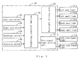
- FIG. 3 is a block diagram of the left/right turn indicator.
- a left/right turn indicator 30 includes a headlight driving unit 32, a turn signal light driving unit 33, a left turn switch 21, a right turn switch 22, and a lighting control device 31, etc.
- the headlight driving unit 32 turns on or off left and right headlights 12 and 13 respectively provided on the left and right sides of the front part of a vehicle 10.
- the turn signal light driving unit 33 turns on or off left and right turn signal lights 14 and 15.
- the left and right turn switches 21 and 22 are left/right turn detection units for detecting left and right turn operations of a turn signal lever 19 provided in the vehicle 10.
- the lighting control device 31 causes the headlight driving unit 32 to change the left headlight 12 from a normal lighting state to left turn indication in accordance with the detection result.
- the lighting control device 31 causes the headlight driving unit 32 to change the right headlight 13 from a normal lighting state to right turn indication in accordance with the detection result.
- the left and right headlights 12 and 13 are constituted of left and right main lights 12a and 13a with large size, provided on the upper side, and left and right small lights 12b and 13b provided on the lower side.
- the left and right turn signal lights 14 and 15 are arranged adjacent to the outside in the lateral direction of each of the main lights 12a and 13a.
- the turn signal lever 19 protruding from a column 18 of a steering 17 is operated to be bent upward from a neutral position to turn on the left turn switch 21 which is the left turn detection unit. Meanwhile, the turn signal lever 19 is operated to be bent downward to turn on the right turn switch 22 which is the right turn detection unit. Further, a headlight operation part 23 is provided at the top of the turn signal lever 19.
- the headlight operation part 23 is operated and rotated to thereby turn on or off a headlight switch 24.
- the main lights 12a and 13a can be switched into two states of a lighting state with normal brightness (low light) and a lighting state with higher brightness than normal (high light).
- the small lights 12b and 13b remain single brightness.
- a lighting state selection lever 25 is provided on the lower side of the headlight operation part 23 of the turn signal lever 19.
- the lighting state selection lever 25 switches turning on/off of a selection switch 26 used for selecting whether or not the left and right headlights 12 and 13 are caused to perform left or right turn indication.
- the lighting state selection lever 25 and the selection switch 26 constitute indication selection means.
- the selection switch 26 is turned off, and each of the headlights 12 and 13 are in a normal lighting state.
- the lighting state selection lever 25 is rotated clockwise, whereby the selection switch 26 is turned on, and the left and right headlights 12 and 13 are caused to perform the left or right turn indication in response to the left or right turn operation of the turn signal lever 19.
- the vehicle 10 includes therein the left turn switch 21, the right turn switch 22, the headlight switch 24, the selection switch 26, the lighting control device 31, the headlight driving unit 32, and the turn signal light driving unit 33. These components constitute the left/right turn indicator 30.
- the lighting control device 31 performs lighting control of the left and right headlights 12 and 13 and the left and right turn signal lights 14 and 15.
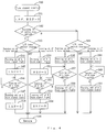
- the lighting control device 31 has a microcomputer including a CPU, a ROM, a RAM, an I/O,etc. As shown in FIG. 3 , the lighting control device 31 cooperates with the left turn switch 21, the right turn switch 22, the headlight switch 24, the selection switch 26, the headlight driving unit 32, and the turn signal light driving unit 33 in executing a "turn signal control program" shown in FIG. 4 and a "headlight lighting control program” shown in FIG. 5 . In these programs, S represents a step, Y represents a determination of "YES”, and N represents a determination of "NO". The lighting control device 31 is connected on the input side to the left turn switch 21, the right turn switch 22, the headlight switch 24, and the selection switch 26. Meanwhile, the lighting control device 31 is connected on the output side to the headlight driving unit 32 for driving the left and right headlights 12 and 13 and the turn signal light driving unit 33 for driving the left and right turn signal lights 14 and 15.
- S represents a step
- Y represents a determination of "YES”
- N represents
- the lighting control device 31 starts the execution of the "turn signal control program" shown in FIG. 4 at step 40 (hereinafter indicated as S40) and, at the same time, starts the execution of the "headlight lighting control program” shown in FIG. 5 at S70.
- the headlight switch 24 is turned on by virtue of the rotating operation of the headlight operation part 23.
- the left and right main lights 12a and 13a are made into the lighting state with normal brightness, and the left and right small lights 12b and 13b are turned on (S71 and S72).
- left and right turn signal switch flags LSF and RSF are respectively set to "0" (S41).
- the selection switch 26 is turned on (S42), so that the left and right headlights 12 and 13 are caused to perform the left or right turn indication in response to the left or right turn operation of the turn signal lever 19.
- the turn signal lever 19 is not operated yet, and therefore, the left and right turn switches 21 and 22 are turned off (S43 and S49).
- the left and right turn signal switch flags LSF and RSF are set to "0".
- the left and right turn signal switch flags LSF and RSF are set to "1".
- the left and right turn signal switch flags LSF and RSF are read (S72 and S73).
- the left and right main lights 12a and 13a are made into the lighting state with normal brightness, and the left and right small lights 12b and 13b are turned on.
- the judgments in S74 and S75 is "NO", whereby the lighting state is maintained.
- the left turn switch 21 When the left turn operation of the turn signal lever 19 is performed, the left turn switch 21 is turned on, and thus the left turn signal light 14 is turned on, whereby the left turn signal switch flag LSF is changed to "1" (S43, S44, and S45).
- the left main light 12a is turned off by the headlight driving unit 32, and this state is maintained until the left turn operation is released (S74, S77, and S78).
- the left small light 12b remains turned on.
- the left turn switch 21 When the left turn operation of the turn signal lever 19 is released, the left turn switch 21 is turned off, and thus the left turn signal light 14 is turned off, whereby the left turn signal switch flag LSF is changed to "0" (S46, S47, and S48).
- the left main light 12a is turned on by the headlight driving unit 32 (S79), and the processing from S74 to S76 is repeated until the headlight switch 24 is turned off to turn off the headlights 12 and 13 (S76).
- the right turn switch 22 When the right turn operation of the turn signal lever 19 is performed, the right turn switch 22 is turned on, and thus the right turn signal light 15 is turned on, whereby the right turn signal switch flag RSF is changed to "1" (S43, S50, and S51).
- the right main light 13a is turned off by the headlight driving unit 32, and this state is maintained until the right turn operation is released (S75, S80, and S81).
- the right small light 13b remains turned on.
- the right turn switch 22 When the right turn operation of the turn signal lever 19 is released, the right turn switch 22 is turned off, and thus the right turn signal light 15 is turned on, whereby the right turn signal switch flag RSF is changed to "0" (S52, S53, and S54).
- the right main light 13a is turned on by the head light driving unit 32 (S81 and S82), and the processing from S74 to S79 is repeated until the headlight switch 24 is turned off to turn off the headlights 12 and 13 (S76).
- the headlight switch 24 is turned off at, for example, the end of the driving of the vehicle, the headlights 12 and 13 are turned off (S76, S83, and S84).
- the turn signal lever 19 provided in the vehicle 10 is operated for a left turn operation, and in response to this operation, the left turn signal light 14 is turned on, and, at the same time, the left main light 12a is made into a turned-off state corresponding to the left turn indication.
- the right turn operation of the turn signal lever 19 is performed, the right turn signal light 15 is turned on, and, at the same time, the right main light 13a is made into a turned-off state corresponding to the right turn indication, in response to the operation.
- the lighting states of the left and right turn signal lights 14 and 15 can be relatively clearly recognized. Consequently, in this embodiment, it is convenient because, in the dark environment such as nighttime where the left and right headlights 12 and 13 are made into the normal lighting state, oncoming vehicles and pedestrians can clearly recognize that the left or right main light 12a or 13a is changed from the normal lighting state to the turned-off state corresponding to the left or right turn indication and thus can surely know the left or right turning of the vehicle 10, and, at the same time, it is very useful in view of road safety. Further, according to this embodiment, the existing headlight can be used as it is, whereby the left and right turn indications can be performed at low cost by using the left and right headlights 12 and 13.
- the lighting state selection lever 25 is not operated, whereby the selection switch 26 remains turned off (S42).
- the left turn switch 21 is turned on, and thus the left turn signal light 14 is turned on; however, the left turn signal switch flag LSF is maintained at "0" (S55 and S56). According to this constitution, the left headlight 12 remains turned on without being affected (S74, S75, and S76).
- the left turn switch 21 When the left turn operation of the turn signal lever 19 is released, the left turn switch 21 is turned off, and thus the left turn signal light 14 is turned off; however, the left turn signal switch flag LSF is maintained at "0", whereby the left headlight 12 remains turned on without being affected (S74, S75, and S76). Also when the right turn operation of the turn signal lever 19 is performed, only the turning on and off of the right turn signal light 15 are performed as in the left turn operation. For this reason, the lighting states of the left and right headlights 12 and 13 are not affected.
- the brightness in the left and right turn indications may be rendered smaller than the brightness in the normal lighting state instead of the turning off of the left and right main lights 12a and 13a.
- the left turn operation of the turn signal lever 19 provided in the vehicle when the left turn operation of the turn signal lever 19 provided in the vehicle is performed, the brightness of the left main light 12a being turned on is, in response to this operation, clearly rendered smaller than normal brightness.
- the right turn operation of the turn signal lever 19 is performed, the brightness of the right main light 13a being turned on is rendered small in response to this operation.
- the brightness of the left and right main lights 12a and 13a, which are being turned on is rendered small. This enables whereby oncoming vehicles and pedestrians to surely know the left or right turning of the vehicle.
- the left and right main lights 12a and 13a may be kept in a normal lighting state instead of being turned off, while the left and right small lights 12b and 13b may be turned off, or the brightness of the left and right small lights 12b and 13b may be rendered smaller than the brightness in the normal lighting state.
- the left turn operation of the turn signal lever 19 provided in the vehicle when the left turn operation of the turn signal lever 19 provided in the vehicle is performed, the left small light 12b being turned on is turned off or the brightness of the left small light 12b is clearly rendered smaller than normal brightness, in response to the operation.
- the right turn operation is performed, the right small right 13b being turned on is turned off or the brightness of the right small light 13b is rendered small, in response to this operation.
- the left and right small lights 12b and 13b which are being turned on, are turned off, or the brightness is rendered small. This enables oncoming vehicles and pedestrians to surely know the left or right turning of the vehicle.
- the left headlight 12 or the right headlight 13 of red, green, or other colors may be turned on in the left or right turn indication.
- lamps emitting different colors are required to be provided in the left and right headlights 12 and 13.
- the headlights 12 and 13 being turned on are changed into a different color, whereby oncoming vehicles and pedestrians can surely know the left or right turning of the vehicle.
- the selection switch 26 is turned on or off by the operation of the lighting state selection lever 25, thereby to select whether or not the left headlight 12 or the right headlight 13 is caused to perform the left or right turn indication.
- the left and right headlights 12 and 13 instead of this, it is possible to cause the left and right headlights 12 and 13 to always perform the left and right turn indications independently of the turning on and off of the selection switch 26.
- omission of S42, S55 to S61 of the "turn signal control program" shown in FIG. 4 allows the left and right headlights 12 and 13 to always perform the left and right turn indications.
- the lighting state selection lever 25 and the selection switch 26 can be omitted, and thus, the structure of the control device can be simplified.
- the left/right turn indicator and each component of the vehicle shown in the above embodiment are merely one example.
- the present invention can be variously modified and practiced without departing from the scope of the present invention.
- a pair of headlights provided on the left and right front sides of a vehicle is used as it is.
- the left headlight is changed from the normal lighting state to the left turn indication
- the right headlight is changed from a normal lighting state to right turn indication.
Landscapes
- Engineering & Computer Science (AREA)
- Mechanical Engineering (AREA)
- Lighting Device Outwards From Vehicle And Optical Signal (AREA)
Applications Claiming Priority (1)
| Application Number | Priority Date | Filing Date | Title |
|---|---|---|---|
| JP2008069751A JP4203534B1 (ja) | 2008-03-18 | 2008-03-18 | 車両の左折右折表示装置 |
Publications (2)
| Publication Number | Publication Date |
|---|---|
| EP2103484A2 true EP2103484A2 (fr) | 2009-09-23 |
| EP2103484A3 EP2103484A3 (fr) | 2010-03-10 |
Family
ID=40325646
Family Applications (1)
| Application Number | Title | Priority Date | Filing Date |
|---|---|---|---|
| EP09003218A Withdrawn EP2103484A3 (fr) | 2008-03-18 | 2009-03-05 | Indicateur de virage à gauche/droite pour véhicule |
Country Status (4)
| Country | Link |
|---|---|
| US (1) | US20090237008A1 (fr) |
| EP (1) | EP2103484A3 (fr) |
| JP (1) | JP4203534B1 (fr) |
| BR (1) | BRPI0900901A2 (fr) |
Families Citing this family (5)
| Publication number | Priority date | Publication date | Assignee | Title |
|---|---|---|---|---|
| JP5348100B2 (ja) | 2010-09-17 | 2013-11-20 | トヨタ自動車株式会社 | 前照灯装置、輝度制御方法 |
| DE102013006045A1 (de) * | 2013-04-06 | 2014-10-09 | GM Global Technology Operations, LLC (n.d. Ges. d. Staates Delaware) | Verfahren zur Steuerung eines Scheinwerfers |
| JP2016084095A (ja) * | 2014-10-28 | 2016-05-19 | ヤンマー株式会社 | 作業車両 |
| JP6413933B2 (ja) * | 2015-06-02 | 2018-10-31 | 株式会社デンソー | 退避走行制御装置、退避走行制御方法 |
| JP7201425B2 (ja) * | 2018-12-26 | 2023-01-10 | 株式会社小糸製作所 | 車両用灯具システム、車両用灯具の制御装置および車両用灯具の制御方法 |
Citations (1)
| Publication number | Priority date | Publication date | Assignee | Title |
|---|---|---|---|---|
| JPH05229384A (ja) | 1991-03-04 | 1993-09-07 | Yasuo Isobe | 自動車の左折、右折明確化装置a |
Family Cites Families (7)
| Publication number | Priority date | Publication date | Assignee | Title |
|---|---|---|---|---|
| US2934744A (en) * | 1958-09-26 | 1960-04-26 | Bank Of America Nat Trust & Savings Ass | Headlight dimmer switch and turn signal control |
| JPH03273950A (ja) * | 1990-03-22 | 1991-12-05 | Mazda Motor Corp | 車両用ランプ装置 |
| JP3075966B2 (ja) * | 1995-08-04 | 2000-08-14 | 本田技研工業株式会社 | 車両用前照灯装置 |
| JPH1029462A (ja) * | 1996-07-15 | 1998-02-03 | Honda Access Corp | 車両用ヘッドライト制御装置 |
| US5769524A (en) * | 1996-12-12 | 1998-06-23 | Yuan; Zhiping | Vehicle lighting systems with side lights |
| GB0000723D0 (en) * | 2000-01-14 | 2000-03-08 | Lewis Maurice L | Vehicle directional indicators |
| AT7317U1 (de) * | 2003-09-23 | 2005-01-25 | Zizala Lichtsysteme Gmbh | Fahrzeugscheinwerfer für kurvenlicht |
-
2008
- 2008-03-18 JP JP2008069751A patent/JP4203534B1/ja not_active Expired - Fee Related
-
2009
- 2009-03-05 EP EP09003218A patent/EP2103484A3/fr not_active Withdrawn
- 2009-03-13 US US12/403,803 patent/US20090237008A1/en not_active Abandoned
- 2009-03-18 BR BRPI0900901-9A patent/BRPI0900901A2/pt not_active IP Right Cessation
Patent Citations (1)
| Publication number | Priority date | Publication date | Assignee | Title |
|---|---|---|---|---|
| JPH05229384A (ja) | 1991-03-04 | 1993-09-07 | Yasuo Isobe | 自動車の左折、右折明確化装置a |
Also Published As
| Publication number | Publication date |
|---|---|
| JP4203534B1 (ja) | 2009-01-07 |
| BRPI0900901A2 (pt) | 2009-12-01 |
| JP2009220773A (ja) | 2009-10-01 |
| EP2103484A3 (fr) | 2010-03-10 |
| US20090237008A1 (en) | 2009-09-24 |
Similar Documents
| Publication | Publication Date | Title |
|---|---|---|
| EP2103484A2 (fr) | Indicateur de virage à gauche/droite pour véhicule | |
| CN112004717A (zh) | 车辆用照明开关以及车辆用照明系统 | |
| EP3700779B1 (fr) | Procédé et système de commande de dispositifs d'éclairage extérieurs sur un véhicule | |
| JP4621994B2 (ja) | フォグランプ装置 | |
| JP2016124502A (ja) | 車両用表示装置 | |
| US12077099B2 (en) | Status detection method and device for vehicle light signaling control device, and vehicle | |
| CN108025671B (zh) | 车辆远光灯控制装置及其方法 | |
| JP2010081318A (ja) | 車両用視界確認装置 | |
| KR200461161Y1 (ko) | 차량 위치 알림 장치 | |
| JP4900338B2 (ja) | オートライトシステム | |
| JP2020196291A (ja) | 車両用制御装置 | |
| KR100877852B1 (ko) | 차량의 라이트 자동 제어 장치 | |
| KR100385510B1 (ko) | 자동차의비상등점등제어장치및그방법 | |
| KR100245844B1 (ko) | 차량의 방향지시 및 비상등 장치 | |
| KR200164115Y1 (ko) | 전조등 자동 점멸장치 | |
| KR20230083449A (ko) | 차량의 방향지시등 조도 제어 방법 및 장치 | |
| JP4252878B2 (ja) | 自動二輪車のヘッドライト制御装置 | |
| KR200394799Y1 (ko) | 안개등 자동점멸장치 | |
| KR0113072Y1 (ko) | 방향지시등 단선경고등회로 | |
| KR0121054Y1 (ko) | 자동차의 방향 지시장치 | |
| KR200275211Y1 (ko) | 자동차용 전조등의 복원장치 | |
| JP2025167893A (ja) | 鞍乗型車両用表示装置 | |
| KR100427237B1 (ko) | 차량용 다기능 전조등장치 | |
| KR20100020201A (ko) | 브레이크 램프 제어 시스템 | |
| KR200252942Y1 (ko) | 자동차용 전조등 자동점멸장치 |
Legal Events
| Date | Code | Title | Description |
|---|---|---|---|
| PUAI | Public reference made under article 153(3) epc to a published international application that has entered the european phase |
Free format text: ORIGINAL CODE: 0009012 |
|
| AK | Designated contracting states |
Kind code of ref document: A2 Designated state(s): AT BE BG CH CY CZ DE DK EE ES FI FR GB GR HR HU IE IS IT LI LT LU LV MC MK MT NL NO PL PT RO SE SI SK TR |
|
| AX | Request for extension of the european patent |
Extension state: AL BA RS |
|
| PUAL | Search report despatched |
Free format text: ORIGINAL CODE: 0009013 |
|
| AK | Designated contracting states |
Kind code of ref document: A3 Designated state(s): AT BE BG CH CY CZ DE DK EE ES FI FR GB GR HR HU IE IS IT LI LT LU LV MC MK MT NL NO PL PT RO SE SI SK TR |
|
| AX | Request for extension of the european patent |
Extension state: AL BA RS |
|
| AKY | No designation fees paid | ||
| STAA | Information on the status of an ep patent application or granted ep patent |
Free format text: STATUS: THE APPLICATION IS DEEMED TO BE WITHDRAWN |
|
| 18D | Application deemed to be withdrawn |
Effective date: 20100911 |
|
| REG | Reference to a national code |
Ref country code: DE Ref legal event code: R108 Effective date: 20110222 Ref country code: DE Ref legal event code: 8566 |