EP2103492A1 - Organe de commande de véhicule, procédé de commande, support d'enregistrement et programme d'enregistrement pour mettre en uvre ce procédé - Google Patents
Organe de commande de véhicule, procédé de commande, support d'enregistrement et programme d'enregistrement pour mettre en uvre ce procédé Download PDFInfo
- Publication number
- EP2103492A1 EP2103492A1 EP07831790A EP07831790A EP2103492A1 EP 2103492 A1 EP2103492 A1 EP 2103492A1 EP 07831790 A EP07831790 A EP 07831790A EP 07831790 A EP07831790 A EP 07831790A EP 2103492 A1 EP2103492 A1 EP 2103492A1
- Authority
- EP
- European Patent Office
- Prior art keywords
- degree
- vehicle
- increasing
- larger
- accelerator pedal
- Prior art date
- Legal status (The legal status is an assumption and is not a legal conclusion. Google has not performed a legal analysis and makes no representation as to the accuracy of the status listed.)
- Granted
Links
Images


Classifications
-
- B—PERFORMING OPERATIONS; TRANSPORTING
- B60—VEHICLES IN GENERAL
- B60T—VEHICLE BRAKE CONTROL SYSTEMS OR PARTS THEREOF; BRAKE CONTROL SYSTEMS OR PARTS THEREOF, IN GENERAL; ARRANGEMENT OF BRAKING ELEMENTS ON VEHICLES IN GENERAL; PORTABLE DEVICES FOR PREVENTING UNWANTED MOVEMENT OF VEHICLES; VEHICLE MODIFICATIONS TO FACILITATE COOLING OF BRAKES
- B60T7/00—Brake-action initiating means
- B60T7/12—Brake-action initiating means for automatic initiation; for initiation not subject to will of driver or passenger
- B60T7/122—Brake-action initiating means for automatic initiation; for initiation not subject to will of driver or passenger for locking of reverse movement
-
- B—PERFORMING OPERATIONS; TRANSPORTING
- B60—VEHICLES IN GENERAL
- B60L—PROPULSION OF ELECTRICALLY-PROPELLED VEHICLES; SUPPLYING ELECTRIC POWER FOR AUXILIARY EQUIPMENT OF ELECTRICALLY-PROPELLED VEHICLES; ELECTRODYNAMIC BRAKE SYSTEMS FOR VEHICLES IN GENERAL; MAGNETIC SUSPENSION OR LEVITATION FOR VEHICLES; MONITORING OPERATING VARIABLES OF ELECTRICALLY-PROPELLED VEHICLES; ELECTRIC SAFETY DEVICES FOR ELECTRICALLY-PROPELLED VEHICLES
- B60L15/00—Methods, circuits, or devices for controlling the traction-motor speed of electrically-propelled vehicles
- B60L15/20—Methods, circuits, or devices for controlling the traction-motor speed of electrically-propelled vehicles for control of the vehicle or its driving motor to achieve a desired performance, e.g. speed, torque, programmed variation of speed
- B60L15/2009—Methods, circuits, or devices for controlling the traction-motor speed of electrically-propelled vehicles for control of the vehicle or its driving motor to achieve a desired performance, e.g. speed, torque, programmed variation of speed for braking
-
- B—PERFORMING OPERATIONS; TRANSPORTING
- B60—VEHICLES IN GENERAL
- B60L—PROPULSION OF ELECTRICALLY-PROPELLED VEHICLES; SUPPLYING ELECTRIC POWER FOR AUXILIARY EQUIPMENT OF ELECTRICALLY-PROPELLED VEHICLES; ELECTRODYNAMIC BRAKE SYSTEMS FOR VEHICLES IN GENERAL; MAGNETIC SUSPENSION OR LEVITATION FOR VEHICLES; MONITORING OPERATING VARIABLES OF ELECTRICALLY-PROPELLED VEHICLES; ELECTRIC SAFETY DEVICES FOR ELECTRICALLY-PROPELLED VEHICLES
- B60L3/00—Electric devices on electrically-propelled vehicles for safety purposes; Monitoring operating variables, e.g. speed, deceleration or energy consumption
- B60L3/0023—Detecting, eliminating, remedying or compensating for drive train abnormalities, e.g. failures within the drive train
- B60L3/0038—Detecting, eliminating, remedying or compensating for drive train abnormalities, e.g. failures within the drive train relating to sensors
-
- B—PERFORMING OPERATIONS; TRANSPORTING
- B60—VEHICLES IN GENERAL
- B60L—PROPULSION OF ELECTRICALLY-PROPELLED VEHICLES; SUPPLYING ELECTRIC POWER FOR AUXILIARY EQUIPMENT OF ELECTRICALLY-PROPELLED VEHICLES; ELECTRODYNAMIC BRAKE SYSTEMS FOR VEHICLES IN GENERAL; MAGNETIC SUSPENSION OR LEVITATION FOR VEHICLES; MONITORING OPERATING VARIABLES OF ELECTRICALLY-PROPELLED VEHICLES; ELECTRIC SAFETY DEVICES FOR ELECTRICALLY-PROPELLED VEHICLES
- B60L50/00—Electric propulsion with power supplied within the vehicle
- B60L50/50—Electric propulsion with power supplied within the vehicle using propulsion power supplied by batteries or fuel cells
- B60L50/51—Electric propulsion with power supplied within the vehicle using propulsion power supplied by batteries or fuel cells characterised by AC-motors
-
- B—PERFORMING OPERATIONS; TRANSPORTING
- B60—VEHICLES IN GENERAL
- B60L—PROPULSION OF ELECTRICALLY-PROPELLED VEHICLES; SUPPLYING ELECTRIC POWER FOR AUXILIARY EQUIPMENT OF ELECTRICALLY-PROPELLED VEHICLES; ELECTRODYNAMIC BRAKE SYSTEMS FOR VEHICLES IN GENERAL; MAGNETIC SUSPENSION OR LEVITATION FOR VEHICLES; MONITORING OPERATING VARIABLES OF ELECTRICALLY-PROPELLED VEHICLES; ELECTRIC SAFETY DEVICES FOR ELECTRICALLY-PROPELLED VEHICLES
- B60L7/00—Electrodynamic brake systems for vehicles in general
- B60L7/24—Electrodynamic brake systems for vehicles in general with additional mechanical or electromagnetic braking
- B60L7/26—Controlling the braking effect
-
- B—PERFORMING OPERATIONS; TRANSPORTING
- B60—VEHICLES IN GENERAL
- B60T—VEHICLE BRAKE CONTROL SYSTEMS OR PARTS THEREOF; BRAKE CONTROL SYSTEMS OR PARTS THEREOF, IN GENERAL; ARRANGEMENT OF BRAKING ELEMENTS ON VEHICLES IN GENERAL; PORTABLE DEVICES FOR PREVENTING UNWANTED MOVEMENT OF VEHICLES; VEHICLE MODIFICATIONS TO FACILITATE COOLING OF BRAKES
- B60T8/00—Arrangements for adjusting wheel-braking force to meet varying vehicular or ground-surface conditions, e.g. limiting or varying distribution of braking force
- B60T8/17—Using electrical or electronic regulation means to control braking
- B60T8/175—Brake regulation specially adapted to prevent excessive wheel spin during vehicle acceleration, e.g. for traction control
-
- B—PERFORMING OPERATIONS; TRANSPORTING
- B60—VEHICLES IN GENERAL
- B60L—PROPULSION OF ELECTRICALLY-PROPELLED VEHICLES; SUPPLYING ELECTRIC POWER FOR AUXILIARY EQUIPMENT OF ELECTRICALLY-PROPELLED VEHICLES; ELECTRODYNAMIC BRAKE SYSTEMS FOR VEHICLES IN GENERAL; MAGNETIC SUSPENSION OR LEVITATION FOR VEHICLES; MONITORING OPERATING VARIABLES OF ELECTRICALLY-PROPELLED VEHICLES; ELECTRIC SAFETY DEVICES FOR ELECTRICALLY-PROPELLED VEHICLES
- B60L2250/00—Driver interactions
- B60L2250/26—Driver interactions by pedal actuation
-
- B—PERFORMING OPERATIONS; TRANSPORTING
- B60—VEHICLES IN GENERAL
- B60T—VEHICLE BRAKE CONTROL SYSTEMS OR PARTS THEREOF; BRAKE CONTROL SYSTEMS OR PARTS THEREOF, IN GENERAL; ARRANGEMENT OF BRAKING ELEMENTS ON VEHICLES IN GENERAL; PORTABLE DEVICES FOR PREVENTING UNWANTED MOVEMENT OF VEHICLES; VEHICLE MODIFICATIONS TO FACILITATE COOLING OF BRAKES
- B60T2201/00—Particular use of vehicle brake systems; Special systems using also the brakes; Special software modules within the brake system controller
- B60T2201/06—Hill holder; Start aid systems on inclined road
-
- B—PERFORMING OPERATIONS; TRANSPORTING
- B60—VEHICLES IN GENERAL
- B60T—VEHICLE BRAKE CONTROL SYSTEMS OR PARTS THEREOF; BRAKE CONTROL SYSTEMS OR PARTS THEREOF, IN GENERAL; ARRANGEMENT OF BRAKING ELEMENTS ON VEHICLES IN GENERAL; PORTABLE DEVICES FOR PREVENTING UNWANTED MOVEMENT OF VEHICLES; VEHICLE MODIFICATIONS TO FACILITATE COOLING OF BRAKES
- B60T2270/00—Further aspects of brake control systems not otherwise provided for
- B60T2270/40—Failsafe aspects of brake control systems
- B60T2270/413—Plausibility monitoring, cross check, redundancy
-
- Y—GENERAL TAGGING OF NEW TECHNOLOGICAL DEVELOPMENTS; GENERAL TAGGING OF CROSS-SECTIONAL TECHNOLOGIES SPANNING OVER SEVERAL SECTIONS OF THE IPC; TECHNICAL SUBJECTS COVERED BY FORMER USPC CROSS-REFERENCE ART COLLECTIONS [XRACs] AND DIGESTS
- Y02—TECHNOLOGIES OR APPLICATIONS FOR MITIGATION OR ADAPTATION AGAINST CLIMATE CHANGE
- Y02T—CLIMATE CHANGE MITIGATION TECHNOLOGIES RELATED TO TRANSPORTATION
- Y02T10/00—Road transport of goods or passengers
- Y02T10/60—Other road transportation technologies with climate change mitigation effect
- Y02T10/64—Electric machine technologies in electromobility
-
- Y—GENERAL TAGGING OF NEW TECHNOLOGICAL DEVELOPMENTS; GENERAL TAGGING OF CROSS-SECTIONAL TECHNOLOGIES SPANNING OVER SEVERAL SECTIONS OF THE IPC; TECHNICAL SUBJECTS COVERED BY FORMER USPC CROSS-REFERENCE ART COLLECTIONS [XRACs] AND DIGESTS
- Y02—TECHNOLOGIES OR APPLICATIONS FOR MITIGATION OR ADAPTATION AGAINST CLIMATE CHANGE
- Y02T—CLIMATE CHANGE MITIGATION TECHNOLOGIES RELATED TO TRANSPORTATION
- Y02T10/00—Road transport of goods or passengers
- Y02T10/60—Other road transportation technologies with climate change mitigation effect
- Y02T10/70—Energy storage systems for electromobility, e.g. batteries
-
- Y—GENERAL TAGGING OF NEW TECHNOLOGICAL DEVELOPMENTS; GENERAL TAGGING OF CROSS-SECTIONAL TECHNOLOGIES SPANNING OVER SEVERAL SECTIONS OF THE IPC; TECHNICAL SUBJECTS COVERED BY FORMER USPC CROSS-REFERENCE ART COLLECTIONS [XRACs] AND DIGESTS
- Y02—TECHNOLOGIES OR APPLICATIONS FOR MITIGATION OR ADAPTATION AGAINST CLIMATE CHANGE
- Y02T—CLIMATE CHANGE MITIGATION TECHNOLOGIES RELATED TO TRANSPORTATION
- Y02T10/00—Road transport of goods or passengers
- Y02T10/60—Other road transportation technologies with climate change mitigation effect
- Y02T10/72—Electric energy management in electromobility
Definitions
- the present invention relates generally to controlling vehicles subjected to brake hold control, and particularly to controlling vehicles in which the brake hold control is cancelled once a degree of operation of an accelerator pedal has attained a predetermined value.
- a vehicle including an automatic transmission that reduces a burden on a driver operating a brake in a traffic jam and the like. More specifically, when the vehicle is stopped in a forward position and in that condition once the vehicle has the brake pedal operated to a degree (e.g., in an amount) larger than a predetermined degree, then thereafter even if the brake pedal is not operated the braking force applied when the vehicle is stopped is held (i.e., brake hold control is exerted). In starting a vehicle subjected to the brake hold control, when the driver releases his/her foot from the brake pedal, a force applied to brake the vehicle when the vehicle is stopped is held.
- a degree e.g., in an amount
- the vehicle subjected to the brake hold control is adapted such that when the driver operates the accelerator pedal the brake hold control can be cancelled to start the vehicle.
- the brake hold control can be cancelled to start the vehicle.
- the accelerator pedal when the accelerator pedal is pressed the brake hold control is cancelled, and the acceleration attributed to the engine and that attributed to the downhill road are simultaneously exerted and the vehicle may suddenly start.
- Japanese Patent Laying-Open No. 10-329671 discloses a technique.
- Japanese Patent Laying-Open No. 10-329671 discloses a brake control system including a brake hold function. More specifically, when a vehicle is stopped and the driver releases his/her foot from the brake pedal, the function holds a braking pressure applied from a master cylinder linked with the brake pedal.
- the brake control system includes a gradient determination unit determining a gradient of a road at least from a degree of operation of an accelerator pedal of the vehicle, and a control unit exerting control to release the held braking pressure if the road's gradient is a downhill gradient.
- the brake control system allows a road's gradient to be determined at least from a degree of operation of an accelerator pedal and if the gradient is a downhill gradient a held braking pressure is released.
- the held braking pressure has been released.
- the acceleration attributed to the engine and that attributed to the downhill road are not simultaneously exerted and the vehicle can avoid suddenly starting.
- a degree of operation of an accelerator pedal that has attained a predetermined value may be considered as the driver's request for acceleration and the brake hold control may accordingly be cancelled.
- the brake hold control is cancelled, and if at that time a driving force having a magnitude corresponding to the degree of operation of the accelerator pedal that has the predetermined value has been output, the vehicle may suddenly start.
- Japanese Patent Laying-Open No. 10-329671 is silent on how the brake control system operates for canceling brake hold control when a degree of operation of the accelerator pedal attains the predetermined value.
- the present invention has been made to overcome the above disadvantage, and it contemplates a vehicular control device, a method of controlling a vehicle, and a storage medium having stored therein a program that implements the method, that can reduce wasteful energy consumption in a vehicle for which brake hold control is cancelled in accordance with a degree of a request made by a driver for acceleration and that can also prevent the vehicle from suddenly starting when the brake hold control is cancelled.
- the present control device controls a vehicle.
- the vehicle is subjected to brake hold control controlling a braking device to hold a force braking the vehicle, as based on a state of the vehicle, while the driver of the vehicle does not press a brake pedal.
- the brake hold control is stopped when a first degree detected as an actual value of a degree of a request made by the driver for acceleration exceeds a predetermined degree.
- the control device comprises: a detection unit for detecting the first degree; a degree setting unit for setting a second degree used as a controlled value of the degree of the request made by the driver for acceleration, to control a force output to drive the vehicle; and a control unit for controlling the force output to drive the vehicle, as based on the second degree.
- the degree setting unit includes a determination unit for determining whether the first degree is larger than the predetermined degree while the brake hold control is exerted, a setting unit for setting the second degree to be smaller than the first degree until a decision is made that the first degree is larger than the predetermined degree, and an increasing unit for increasing the second degree to gradually approach the first degree when a decision is made that the first degree is larger than the predetermined degree.
- brake hold control is stopped when a first degree detected as an actual value of a degree of a request made by a driver for acceleration (e.g., an actual value of a degree of operation of an accelerator pedal) exceeds a predetermined degree. Until a decision is made that the first degree is larger than the predetermined degree, a second degree used as a controlled value of the degree of the request made by the driver for acceleration, to control a force output to drive the vehicle (e.g., a controlled value of the degree of operation of the accelerator pedal) is set to be smaller than the first degree (e.g., approximately at zero).
- the second degree is increased to gradually approach the first degree. This allows a driving force to be increased more gradually than setting the second degree to the same value as the first degree immediately after the first degree is larger than the predetermined degree, and the vehicle can be prevented from suddenly starting.
- a control device can be provided that allows a vehicle for which brake hold control is cancelled based on a degree of a request from a driver for acceleration to reduce wasteful energy consumption and that can also prevent the vehicle from suddenly starting when the brake hold control is cancelled.
- the increasing unit increases the second degree based on a difference between the first degree and the second degree.
- a difference between the first degree and the second degree can be said to be a difference between a driving force corresponding to the driver's request for acceleration and an actual driving force. Accordingly, the second degree is increased based on the difference between the first degree and the second degree. The actual driving force can thus be increased based on the difference between the driving force corresponding to the driver's request for acceleration and the actual driving force.
- the increasing unit increases the second degree at a rate allowing an amount increased for a predetermined time to be equal to the difference that is provided when the brake hold control is stopped.
- the second degree is increased at a rate allowing an amount increased for a predetermined time to be equal to the difference that is provided when the brake hold control is stopped. Accordingly, a driving force can be increased gradually at a constant rate by adjusting the predetermined period of time.
- the increasing unit increases the second degree by a larger amount for the difference that is larger.
- the present invention it can be said that when the first degree has larger differences from the second degree, the driving force corresponding to the driver's request for acceleration has larger differences from the actual driving force. Accordingly, when the first degree has larger differences from the second degree, the second degree is increased by a larger amount. Thus when the first degree has larger differences from the second degree, the second degree can be converged to the first degree in smaller periods of time to faster output a driving force corresponding to the driver's request for acceleration.
- the increasing unit increases the second degree based on the first degree.
- the second degree is increased based on the first degree.
- An actual driving force can thus be increased based on a degree of a request made by the driver for acceleration.
- the increasing unit increases the second degree by a larger amount for the first degree that is larger.
- the second degree is increased by a larger amount for the first degree that is larger.
- the second degree can be converged to the first degree in a smaller period of time to faster output a driving force corresponding to the driver's request for larger acceleration.
- the present embodiment provides a control device mounted in an electric vehicle 20 configured as will be described hereinafter.
- the present control device is not only applicable to the Fig. 1 electric vehicle: it is applicable to an electric vehicle having a different manner.
- the vehicle may not be an electric vehicle: it may be a hybrid vehicle traveling by the motive power of an engine and a motor.
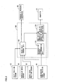
- Electric vehicle 20 includes wheels 22A, 22B, 22C, 22D, a propeller shaft 26 connected to wheels 22A, 22B via a differential gear 24, a motor 30 outputting motive power to propeller shaft 26 for driving the wheels for traveling, a battery 36 supplying motor 30 with electric power via an inverter 34, and an electronic control unit (ECU) 100 generally controlling electric vehicle 20.
- ECU electronice control unit
- Motor 30 is configured for example as a well known, permanent magnetic (PM) type, synchronous motor generator and driven by 3-phase alternate current electric power received from inverter 34.
- PM permanent magnetic
- Inverter 34 is configured as a well known inverter circuit having 6 switching elements, and receives direct current electric power from battery 36 and supplies it for example by pulse width modulation (PWM) control as pseudo 3-phase alternate current electric power to motor 30.
- PWM pulse width modulation
- ECU 100 is configured as a microprocessor with a central processing unit (CPU) 102 serving as a center, and has other than CPU 102 a read only memory (ROM) 104 storing a processing program, a random access memory (RAM) 106 temporarily storing data, and an input/output port (not shown).
- CPU central processing unit
- ROM read only memory
- RAM random access memory
- Electric vehicle 20 further includes a brake disk 62 provided at a drive shaft 28 connected to wheel 22D, a brake mechanism 64, a brake pipe 66, and a hydraulic pressure controller 68.
- brake disk 62, brake mechanism 64 and brake pipe 66 may be provided for each wheel 22A, 22B, 22C, 22D.
- Brake mechanism 64 receives the pressure of a brake fluid introduced into brake pipe 66 and in accordance with the brake fluid's pressure received sandwiches brake disk 62 to generate frictional braking force (hydraulic brake).
- the brake fluid's pressure in brake pipe 66 is adjusted by hydraulic pressure controller 68.
- Hydraulic pressure controller 68 receives a brake control signal from ECU 100 and outputs the brake fluid's pressure to brake pipe 66 in accordance with the brake control signal.
- ECU 100 receives: a detection signal ⁇ from a rotational position detection sensor 32 detecting a rotational position of a rotor of motor 30; phase currents iu, iv, iw from a current sensor (not shown) attached to each phase of inverter 34; a shift position SP from a shift position sensor 52 detecting a position at which a shift lever 51 is operated; an actual value of a degree of operation of an accelerator pedal from an accelerator pedal position sensor 54 detecting an amount by which accelerator pedal 53 is operated; an amount by which brake pedal 55 is operated BP from a brake pedal position sensor 56 detecting the amount by which the brake pedal is operated; vehicular speed V from a vehicular speed sensor 58; and the like through an input port.
- Accelerator pedal position sensor 54 detects as a degree of a request made by a driver for acceleration an actual value of a degree of operation of the accelerator pedal, and accelerator pedal position sensor 54 transmits to ECU 100 a signal representing a result of the detection.
- An actual value of a degree of operation of the accelerator pedal as referred to herein, means a ratio of a current amount of operation of accelerator pedal 53 relative to a maximum amount of operation of accelerator pedal 53.
- the present invention is not limited to that accelerator pedal position sensor 54 detects an actual value of a degree of operation of the accelerator pedal.
- accelerator pedal position sensor 54 may detect a current amount of operation of accelerator pedal 53
- ECU 100 may detect an actual value of a degree of operation of the accelerator pedal.
- Accelerator pedal position sensor 54 includes two position sensors (not shown), i.e., a sensor for control and a sensor for anomaly detection, to ensure reliability for detection.
- the sensor for control and the sensor for anomaly detection have different output characteristics, as shown in Fig. 2 .
- the sensor for control and the sensor for anomaly detection have their respective output voltage values with a difference of V(0) for an actual value of a degree of operation of the accelerator pedal of zero.
- the sensor for control and the sensor for anomaly detection normally function, and an actual value of a degree of operation of the accelerator pedal increases, the sensor for control and the sensor for anomaly detection have their respective output voltage values having a characteristic increasing the values at the same rate. Their respective output voltage values thus have a difference held at V(0).
- This characteristic is utilized to allow accelerator pedal position sensor 54 to monitor a voltage difference VA(0) for an actual value of a degree of operation of the accelerator pedal of a degree A(0), and if voltage difference VA(0) is maintained at V(0), a decision is made that accelerator pedal position sensor 54 normally functions. In other words, to ensure the driver's request for acceleration in reliability, it is necessary that an actual value of a degree of operation of the accelerator pedal be larger than degree A(0) as predetermined.
- ECU 100 receives signals from a brake fluid pressure sensor 72 and a brake hold switch 74 via an input port.
- Brake fluid pressure sensor 72 detects the brake fluid's pressure in brake pipe 66 that is adjusted by hydraulic pressure controller 68, and brake fluid pressure sensor 72 transmits to ECU 100 a signal representing a result of detecting the pressure.
- Brake hold switch 74 is operated by a driver to select whether the driver desires to exert brake hold control, as will be described later. If brake hold switch 74 is turned on, brake hold switch 74 transmits to ECU 100 a signal representing that the driver desires to exert the brake hold control. If brake hold switch 74 is turned off, brake hold switch 74 transmits to ECU 100 a signal representing that the driver does not desire to exert the brake hold control.
- ECU 100 sets a controlled value of a degree of operation of the accelerator pedal based on an actual value of the degree of operation of the accelerator pedal and the vehicle's condition.
- the controlled value of the degree of operation of the accelerator pedal is used as a controlled value of a degree of a request made by a driver for acceleration, to control a force output to drive the vehicle.
- ECU 100 controls motor 30 to drive motor 30 to cause motor 30 to output a requested torque set based on a controlled value of a degree of operation of the accelerator pedal and vehicular speed V.
- an actual value of a degree of operation of the accelerator pedal is not used directly. Rather, a controlled value of the degree of operation of the accelerator pedal that is set by ECU 100 in accordance with the actual value of the degree of operation of the accelerator pedal, is used.
- ECU 100 When ECU 100 brakes electric vehicle 20, ECU 100 controls motor 30 to drive motor 30 to cause motor 30 to output a braking torque set as based on the amount by which the brake pedal is operated BP and vehicular speed V.
- ECU 100 To allow motor 30 to receive a motor current generating the above requested torque and braking torque, ECU 100 generates a switching control signal controlling a switching element that configures inverter 34 to turn on/off. Inverter 34 performs electric power conversion in response to the switching control signal to supply motor 30 with alternate current electric power.
- ECU 100 exerts the brake hold control to alleviate a burden imposed on the driver's braking operation in a traffic jam or the like. More specifically, ECU 100 detects shift position SP, vehicular speed V, an actual value of a degree of operation of the accelerator pedal, and the amount by which the brake pedal is operated BP.
- shift position SP is a forward position (a D position)
- the actual value of the degree of operation of the accelerator pedal is approximately zero
- vehicular speed V is approximately zero (i.e., the vehicle is currently stopped)
- ECU 100 exerts control such that the braking force applied when the vehicle is stopped is held even if the amount by which the brake pedal is operated BP is reduced after amount BP has exceeded the predetermined threshold value.
- ECU 100 cancels exerting the brake hold control.
- the present embodiment provides a control device to set a controlled value of a degree of operation of the accelerator pedal such that while the brake hold control is exerted the controlled value of the degree of operation of the accelerator pedal is zero and when the actual value of the degree of operation of the accelerator pedal has attained predetermined degree A(0) the controlled value of the degree of operation of the accelerator pedal is gradually converged to the actual value of the degree of operation of the accelerator pedal.
- Fig. 3 is a block diagram in function of the control device in the present embodiment.
- the control device includes an acceleration request determination unit 110, a brake hold control unit 120 connected to acceleration request determination unit 110, and a unit 130 connected to brake hold control unit 120 and setting a controlled value of a degree of operation of the accelerator pedal.
- Acceleration request determination unit 110 receives an actual value of a degree of operation of the accelerator pedal from accelerator pedal position sensor 54 and determines therefrom whether the driver currently requests acceleration.
- Brake hold control unit 120 receives shift position SP from shift position sensor 52, an amount of operation of the brake pedal from brake pedal position sensor 56, vehicular speed V from vehicular speed sensor 58, and a decision made by acceleration request determination unit 110, and outputs in accordance therewith a command signal to a hydraulic pressure controller 60 to exert/cancel the brake hold control.
- Unit 130 setting a controlled value of a degree of operation of the accelerator pedal receives the actual value of the degree of operation of the accelerator pedal and the command signal from accelerator pedal position sensor 54 and brake hold control unit 120, respectively, sets a controlled value of the degree of operation of the accelerator pedal in accordance therewith, and outputs a command signal to inverter 34 to cause motor 30 to output a torque corresponding to the set, controlled value of the degree of operation of the accelerator pedal.
- the control device having such a function block according to the present embodiment can also be implemented by hardware mainly of a configuration of a digital circuit, an analog circuit and the like, or software mainly of CPU 102 and ROM 104 included in ECU 100 and a program read from ROM 104 and executed by CPU 102.
- the control device implemented by hardware is advantageous in speed of operation and that the control device implemented by software is advantageous in changing a design.
- a control device implemented as software is also a manner of the present invention.
- control device executes a program having a structure for control, as will be described hereinafter. Note that this program is repeatedly executed at a predetermined cycle time.
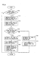
- step (S) 100 ECU 100 determines whether the brake hold control is currently exerted. If so (YES in S100), the control proceeds to S102. Otherwise (NO in S100), the process ends.
- ECU 100 sets a controlled value of a degree of operation of the accelerator pedal at 0.
- ECU 100 detects the actual value of the degree of operation of the accelerator pedal in accordance with a signal received from accelerator pedal position sensor 54.
- ECU 100 determines whether the actual value of the degree of operation of the accelerator pedal is larger than predetermined degree A(0).
- predetermined degree A(0) is a value that allows a decision to be made that accelerator pedal position sensor 54 normally functions and that can ensure the driver's request for acceleration in reliability. If the actual value of the degree of operation of the accelerator pedal is larger than predetermined degree A(0) (YES in S 106), the control proceeds to S112. Otherwise (NO in S 106), the control proceeds to S108.
- ECU 100 determines that there is no request from the driver for acceleration. In S110, ECU 100 outputs a command to hydraulic pressure controller 68 to maintain the brake hold control.
- ECU 100 determines that there is a request from the driver for acceleration.
- ECU 100 outputs a command to hydraulic pressure controller 68 to cancel the brake hold control.
- ECU 100 performs a process to converge the controlled value of the degree of operation of the accelerator pedal.
- control device performs the process to converge the controlled value of the degree of operation of the accelerator pedal by executing a program having a structure for control, as will be described hereinafter.
- ECU 100 calculates a fixed amount for increase.
- ECU 100 calculates the fixed amount for increase so that a difference that an actual value of a degree of operation of the accelerator pedal and a controlled value of the degree of operation of the accelerator pedal have therebetween when the brake hold control is cancelled is converged in a predetermined period of time. More specifically, ECU 100 divides predetermined degree A(0) by the predetermined period of time to obtain the fixed amount for increase.
- the fixed amount for increase may previously be stored.
- ECU 100 increases the controlled value of the degree of operation of the accelerator pedal by the fixed amount for increase.
- ECU 100 detects the actual value of the degree of operation of the accelerator pedal in accordance with a signal received from accelerator pedal position sensor 54.
- ECU 100 determines whether the controlled value of the degree of operation of the accelerator pedal has converged to the actual value of the degree of operation of the accelerator pedal. ECU 100 determines that the former value has converged to the latter value if the values have a difference having a predetermined value or smaller. If ECU 100 determines that the former value has converged to the latter value (YES in S208), the control proceeds to S210. Otherwise (NO in S208), the control returns to S204. In S210, ECU 100 sets the former value to the latter value.
- control device controls electric vehicle 20 to operate, as will be described hereinafter.
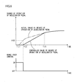
- the controlled value of the degree of operation of the accelerator pedal converges to the actual value of the degree of operation of the accelerator pedal, the controlled value of the degree of operation of the accelerator pedal is gradually increased in a fixed amount for increase (NO in S204, S208).
- motor 30 can output a gradually increasing torque, and the vehicle can be prevented from suddenly starting.
- the present embodiment provides a control device such that before an actual value of a degree of operation of an accelerator pedal attains a predetermined degree a decision is made that there is no request from the driver for acceleration, and the brake hold control is maintained and a controlled value of the degree of operation of the accelerator pedal is set at 0.
- the brake hold control can thus be exerted without a motor driven to wastefully consume electric power.
- a decision is made that there is a request from the driver for acceleration, and the brake hold control is cancelled.
- the controlled value of the degree of operation of the accelerator pedal converges to the actual value of the degree of operation of the accelerator pedal
- the controlled value of the degree of operation of the accelerator pedal is gradually increased in a fixed amount for increase.
- the motor can thus output a gradually increasing torque, and the vehicle can be prevented from suddenly starting when the brake hold control is cancelled.
- the controlled value of the degree of operation of the accelerator pedal is not limited to 0 as long as it is set at a value smaller than the actual value of the degree of operation of the accelerator pedal.
- a second embodiment provides a control device, as will be described hereinafter.
- the control device according to the present embodiment is mounted in an electric vehicle which is different from electric vehicle 20 of the first embodiment only in that ECU 100 executes a program having a different structure for control.
- the remainder in configuration is identical to electric vehicle 20 of the first embodiment.
- Identical configurations are identically denoted. Their names and functions are also identical. Accordingly, they will not be described repeatedly in detail.
- the control device performs a process to converge a controlled value of a degree of operation of an accelerator pedal by executing a program having a structure for control, as will be described hereinafter.
- the steps identical to those in the Fig. 5 flowchart are identically denoted and will not be described repeatedly in detail.
- ECU 100 receives an actual value of a degree of operation of an accelerator pedal from accelerator pedal position sensor 54 and therefrom calculates a variable coefficient for increase.
- the variable coefficient for increase is used to calculate an amount of a controlled value of the degree of operation of the accelerator pedal that should be increased.
- ECU 100 calculates the variable coefficient for increase, for example as based on a map with the actual value of the degree of operation of the accelerator pedal serving as a parameter. In this map, as shown in Fig. 8 , for an actual value of a degree of operation of the accelerator pedal smaller than A(1), a variable coefficient for increase is calculated as 0.
- variable coefficient for increase is calculated to increase to be gradually larger, and for an actual value of the degree of operation of the accelerator pedal larger than A(2), the variable coefficient for increase is calculated as 1.
- how the variable coefficient for increase is calculated is not limited to the above.
- ECU 100 reads an offset amount (a difference between a controlled value of a degree of operation of the accelerator pedal and an actual value of the degree of operation of the accelerator pedal) that was stored when the present program was immediately previously executed.
- ECU 100 calculates a variable amount for increase.
- ECU 100 for example calculates a product of the read, previous offset amount and the calculated, variable coefficient for increase as the variable amount for increase.
- ECU 100 determines whether a fixed amount for increase is larger than the variable amount for increase. If so (YES in step S 1206), the control proceeds to S1208. Otherwise (NO in step S1206), the control proceeds to S1210.
- ECU 100 increases the controlled value of the degree of operation of the accelerator pedal by the fixed amount for increase.
- ECU 100 increases the controlled value of the degree of operation of the accelerator pedal by the variable amount for increase.
- ECU 100 determines whether the controlled value of the degree of operation of the accelerator pedal has converged to the actual value of the degree of operation of the accelerator pedal. ECU 100 determines that the former value has converged to the latter value if the values have a difference having a predetermined value or smaller. If ECU 100 determines that the former value has converged to the latter value (YES in step S 1212), the control proceeds to S210. Otherwise (NO in step S1212), the control proceeds to S 1214.
- ECU 100 stores the difference between the controlled value of the degree of operation of the accelerator pedal and the actual value of the degree of operation of the accelerator pedal as an offset amount.
- control device controls an electric vehicle to operate, as will be described hereinafter.
- a controlled value of the degree of operation of the accelerator pedal is set at 0 (S102) and a decision is also made that there is no request from the driver for acceleration (S108), and the brake hold control is maintained (S 110), similarly as done in the first embodiment.
- the brake hold control can thus be exerted without motor 30 driven to wastefully consume electric power.
- the controlled value of the degree of operation of the accelerator pedal is increased in the larger one of the fixed amount for increase and the variable amount for increase (S126, S1208, S1210).
- the actual value of the degree of operation of the accelerator pedal attains A(1) at time T(6) and the variable coefficient for increase is calculated as a value equal to or larger than 0 (S1200), and as the actual value of the degree of operation of the accelerator pedal increases, the variable amount for increase is larger than the fixed amount for increase at time T(7).
- a controlled value of a degree of operation of the accelerator pedal that is increased only in the fixed amount for increase see a chain double-dashed line in Fig.
- variable amount for increase is calculated as a product of the immediately previous offset amount and the variable coefficient for increase (S1204), and for larger offset amounts, the variable amount for increase can be larger to faster converge the controlled value of the degree of operation of the accelerator pedal to the actual value of the degree of operation of the accelerator pedal, and motor 30 can hence faster output a driving force corresponding to the driver's request for acceleration.
- variable coefficient for increase is set to have a larger value for a larger actual value of a degree of operation of the accelerator pedal (see Fig. 8 ).
- the variable amount for increase can be larger to faster converge a controlled value of the degree of operation of the accelerator pedal to the actual value of the degree of operation of the accelerator pedal.
- Motor 30 can thus faster output a driving force corresponding to the driver's request for acceleration.
- the present embodiment provides a control device such that before an actual value of a degree of operation of an accelerator pedal attains a predetermined degree a decision is made that there is no request from a driver for acceleration, and brake hold control is maintained and a controlled value of the degree of operation of the accelerator pedal is set at 0.
- the brake hold control can thus be exerted without a motor driven to wastefully consume electric power.
- a decision is made that there is a request from the driver for acceleration, and the brake hold control is cancelled.
- the controlled value of the degree of operation of the accelerator pedal is increased in the larger one of a fixed amount for increase and a variable amount for increase calculated based on the actual value of the degree of operation of the accelerator pedal and a difference from the actual value of the degree of operation of the accelerator pedal.
- the controlled value of the degree of operation of the accelerator pedal can be gradually increased to prevent a vehicle from suddenly starting when the brake hold control is cancelled, and a motor can fast output a driving force corresponding to the driver's request for acceleration.
Landscapes
- Engineering & Computer Science (AREA)
- Mechanical Engineering (AREA)
- Transportation (AREA)
- Power Engineering (AREA)
- Sustainable Energy (AREA)
- Life Sciences & Earth Sciences (AREA)
- Sustainable Development (AREA)
- Chemical & Material Sciences (AREA)
- Combustion & Propulsion (AREA)
- Physics & Mathematics (AREA)
- Electromagnetism (AREA)
- Regulating Braking Force (AREA)
- Electric Propulsion And Braking For Vehicles (AREA)
Applications Claiming Priority (2)
| Application Number | Priority Date | Filing Date | Title |
|---|---|---|---|
| JP2007008108A JP4434212B2 (ja) | 2007-01-17 | 2007-01-17 | 車両の制御装置、制御方法、その方法を実現するプログラムおよびそのプログラムを記録した記録媒体 |
| PCT/JP2007/072060 WO2008087789A1 (fr) | 2007-01-17 | 2007-11-07 | Organe de commande de véhicule, procédé de commande, support d'enregistrement et programme d'enregistrement pour mettre en œuvre ce procédé |
Publications (3)
| Publication Number | Publication Date |
|---|---|
| EP2103492A1 true EP2103492A1 (fr) | 2009-09-23 |
| EP2103492A4 EP2103492A4 (fr) | 2013-09-18 |
| EP2103492B1 EP2103492B1 (fr) | 2014-12-17 |
Family
ID=39635795
Family Applications (1)
| Application Number | Title | Priority Date | Filing Date |
|---|---|---|---|
| EP07831790.6A Not-in-force EP2103492B1 (fr) | 2007-01-17 | 2007-11-07 | Organe de commande de véhicule, procédé de commande, support d'enregistrement et programme d'enregistrement pour mettre en uvre ce procédé |
Country Status (4)
| Country | Link |
|---|---|
| US (1) | US8135530B2 (fr) |
| EP (1) | EP2103492B1 (fr) |
| JP (1) | JP4434212B2 (fr) |
| WO (1) | WO2008087789A1 (fr) |
Families Citing this family (12)
| Publication number | Priority date | Publication date | Assignee | Title |
|---|---|---|---|---|
| JP4127310B2 (ja) * | 2006-12-27 | 2008-07-30 | トヨタ自動車株式会社 | 車両の制御装置、制御方法、その方法を実現するプログラムおよびそのプログラムを記録した記録媒体 |
| US9604526B2 (en) * | 2008-12-05 | 2017-03-28 | Ford Global Technologies, Llc | Method for providing improved driveability for a vehicle |
| JP5019002B2 (ja) * | 2009-12-17 | 2012-09-05 | トヨタ自動車株式会社 | 車両の制御装置 |
| WO2012108028A1 (fr) | 2011-02-10 | 2012-08-16 | トヨタ自動車株式会社 | Véhicule hybride et procédé pour la commande de véhicule hybride |
| CN104169148B (zh) * | 2012-03-15 | 2017-03-08 | 日产自动车株式会社 | 混合动力车辆的控制装置 |
| JP6056734B2 (ja) * | 2013-10-25 | 2017-01-11 | トヨタ自動車株式会社 | 車両制御装置 |
| JP6332316B2 (ja) * | 2016-03-29 | 2018-05-30 | マツダ株式会社 | 車両の制御装置 |
| JP6508534B2 (ja) * | 2016-03-29 | 2019-05-08 | マツダ株式会社 | エンジンの制御装置 |
| JP7301466B2 (ja) * | 2019-03-19 | 2023-07-03 | ダイハツ工業株式会社 | 車両制御装置 |
| JP7264036B2 (ja) | 2019-12-13 | 2023-04-25 | トヨタ自動車株式会社 | 車両 |
| CN113815411B (zh) * | 2020-06-19 | 2023-11-14 | 比亚迪股份有限公司 | 标定方法、装置以及存储介质、新能源汽车、控制方法 |
| JP7428852B2 (ja) * | 2021-03-04 | 2024-02-06 | 本田技研工業株式会社 | 鞍乗型車両のブレーキシステム |
Family Cites Families (9)
| Publication number | Priority date | Publication date | Assignee | Title |
|---|---|---|---|---|
| JPH09130909A (ja) | 1995-10-31 | 1997-05-16 | Sanyo Electric Co Ltd | 電気自動車の駆動制御装置 |
| EP0781698B1 (fr) * | 1995-12-27 | 2001-03-14 | Denso Corporation | Dispositif de contrôle de freinage pour un véhicule |
| JPH09286324A (ja) * | 1996-04-23 | 1997-11-04 | Toyota Motor Corp | 制動力制御装置 |
| JPH10329671A (ja) | 1997-05-28 | 1998-12-15 | Fujitsu Ten Ltd | ブレーキ制御システム |
| US7074161B2 (en) * | 2001-05-08 | 2006-07-11 | Continental Teves, Inc. | Method for assisting a vehicle to start on a slope |
| JP2003182404A (ja) * | 2001-12-17 | 2003-07-03 | Aisin Seiki Co Ltd | 電動車輌の坂路停止制御装置 |
| JP4039184B2 (ja) * | 2002-08-29 | 2008-01-30 | 株式会社アドヴィックス | クリープ走行制御装置 |
| JP2006232014A (ja) | 2005-02-23 | 2006-09-07 | Toyota Motor Corp | 車両用制動装置 |
| JP4725281B2 (ja) * | 2005-10-14 | 2011-07-13 | 株式会社アドヴィックス | 車両の制動力保持装置、及び車両の制動力保持方法 |
-
2007
- 2007-01-17 JP JP2007008108A patent/JP4434212B2/ja active Active
- 2007-11-07 US US12/522,224 patent/US8135530B2/en not_active Expired - Fee Related
- 2007-11-07 EP EP07831790.6A patent/EP2103492B1/fr not_active Not-in-force
- 2007-11-07 WO PCT/JP2007/072060 patent/WO2008087789A1/fr not_active Ceased
Also Published As
| Publication number | Publication date |
|---|---|
| EP2103492B1 (fr) | 2014-12-17 |
| US20100076661A1 (en) | 2010-03-25 |
| JP4434212B2 (ja) | 2010-03-17 |
| US8135530B2 (en) | 2012-03-13 |
| JP2008174048A (ja) | 2008-07-31 |
| EP2103492A4 (fr) | 2013-09-18 |
| WO2008087789A1 (fr) | 2008-07-24 |
Similar Documents
| Publication | Publication Date | Title |
|---|---|---|
| EP2103492B1 (fr) | Organe de commande de véhicule, procédé de commande, support d'enregistrement et programme d'enregistrement pour mettre en uvre ce procédé | |
| US8010270B2 (en) | Vehicle controller and control method | |
| US20100198449A1 (en) | Vehicular control device and method of controlling a vehicle | |
| EP2098404B1 (fr) | Dispositif de commande et procédé destiné à un véhicule et support d'enregistrement ayant enregistré sur celui-ci un programme permettant d'exécuter le procédé | |
| US7291090B2 (en) | Motor torque control system for vehicle | |
| US8033955B2 (en) | Methods and systems for regulating hill descent speed of an electric vehicle | |
| US20040262994A1 (en) | Method and device for reducing the brake load at at least one wheel brake | |
| JP5207953B2 (ja) | ハイブリッド自動車のオートクルーズ制御装置及び車両の自動制動制御装置 | |
| EP1327554A1 (fr) | Système de commande de l'entrainement d'un véhicule | |
| JP2009051401A (ja) | 車両用制御装置及び制御システム | |
| JP2001025109A (ja) | 電気自動車のモータトルク制御装置 | |
| JP5775434B2 (ja) | アクセルペダル反力制御装置 | |
| EP4096973B1 (fr) | Commande de vitesse de décélération de véhicule sélectionnable par l'utilisateur permettant de développer au maximum la régénération pour des systèmes de propulsion électrifiés | |
| JP2001080496A (ja) | 電動ブレーキ装置 | |
| KR20110030435A (ko) | 노면에 존재하는 마찰 계수를 고려하면서 전동식으로 구동되는 자동차의 견인 토크를 조절하기 위한 방법 및 상기 방법을 실행하기 위한 장치 | |
| JP2005207327A (ja) | 車両の自動停止始動制御装置 | |
| JP4151139B2 (ja) | 発進クラッチ制御装置 | |
| US20250074206A9 (en) | Braking control device | |
| JP2007043848A (ja) | 車両の制御装置 | |
| JP2005161933A (ja) | ハイブリッド型四輪駆動車両の制御装置 | |
| JP2004001625A (ja) | 制動制御装置 | |
| JP2005282367A (ja) | 車両のアクセルペダル操作荷重制御装置 | |
| JPH118908A (ja) | 電気自動車のモータトルク制御装置 | |
| JPH06144197A (ja) | リターダ制御装置 | |
| JPH0646504A (ja) | 補助制動装置 |
Legal Events
| Date | Code | Title | Description |
|---|---|---|---|
| PUAI | Public reference made under article 153(3) epc to a published international application that has entered the european phase |
Free format text: ORIGINAL CODE: 0009012 |
|
| 17P | Request for examination filed |
Effective date: 20090623 |
|
| AK | Designated contracting states |
Kind code of ref document: A1 Designated state(s): AT BE BG CH CY CZ DE DK EE ES FI FR GB GR HU IE IS IT LI LT LU LV MC MT NL PL PT RO SE SI SK TR |
|
| DAX | Request for extension of the european patent (deleted) | ||
| RAP1 | Party data changed (applicant data changed or rights of an application transferred) |
Owner name: TOYOTA JIDOSHA KABUSHIKI KAISHA |
|
| A4 | Supplementary search report drawn up and despatched |
Effective date: 20130819 |
|
| RIC1 | Information provided on ipc code assigned before grant |
Ipc: B60T 8/175 20060101ALI20130812BHEP Ipc: B60L 15/20 20060101ALI20130812BHEP Ipc: B60L 9/18 20060101ALI20130812BHEP Ipc: B60L 11/00 20060101ALI20130812BHEP Ipc: B60T 7/12 20060101AFI20130812BHEP Ipc: B60L 3/00 20060101ALI20130812BHEP Ipc: B60L 7/26 20060101ALI20130812BHEP Ipc: B60L 11/18 20060101ALI20130812BHEP |
|
| GRAP | Despatch of communication of intention to grant a patent |
Free format text: ORIGINAL CODE: EPIDOSNIGR1 |
|
| RIC1 | Information provided on ipc code assigned before grant |
Ipc: B60L 3/00 20060101ALI20140520BHEP Ipc: B60L 11/18 20060101ALI20140520BHEP Ipc: B60L 15/20 20060101ALI20140520BHEP Ipc: B60L 7/26 20060101ALI20140520BHEP Ipc: B60L 11/00 20060101ALI20140520BHEP Ipc: B60T 8/175 20060101ALI20140520BHEP Ipc: B60L 9/18 20060101ALI20140520BHEP Ipc: B60T 7/12 20060101AFI20140520BHEP |
|
| INTG | Intention to grant announced |
Effective date: 20140606 |
|
| GRAS | Grant fee paid |
Free format text: ORIGINAL CODE: EPIDOSNIGR3 |
|
| GRAA | (expected) grant |
Free format text: ORIGINAL CODE: 0009210 |
|
| AK | Designated contracting states |
Kind code of ref document: B1 Designated state(s): AT BE BG CH CY CZ DE DK EE ES FI FR GB GR HU IE IS IT LI LT LU LV MC MT NL PL PT RO SE SI SK TR |
|
| REG | Reference to a national code |
Ref country code: GB Ref legal event code: FG4D |
|
| REG | Reference to a national code |
Ref country code: CH Ref legal event code: EP |
|
| REG | Reference to a national code |
Ref country code: IE Ref legal event code: FG4D |
|
| REG | Reference to a national code |
Ref country code: AT Ref legal event code: REF Ref document number: 701647 Country of ref document: AT Kind code of ref document: T Effective date: 20150115 |
|
| REG | Reference to a national code |
Ref country code: DE Ref legal event code: R096 Ref document number: 602007039741 Country of ref document: DE Effective date: 20150129 |
|
| PG25 | Lapsed in a contracting state [announced via postgrant information from national office to epo] |
Ref country code: FI Free format text: LAPSE BECAUSE OF FAILURE TO SUBMIT A TRANSLATION OF THE DESCRIPTION OR TO PAY THE FEE WITHIN THE PRESCRIBED TIME-LIMIT Effective date: 20141217 Ref country code: LT Free format text: LAPSE BECAUSE OF FAILURE TO SUBMIT A TRANSLATION OF THE DESCRIPTION OR TO PAY THE FEE WITHIN THE PRESCRIBED TIME-LIMIT Effective date: 20141217 |
|
| REG | Reference to a national code |
Ref country code: LT Ref legal event code: MG4D |
|
| PG25 | Lapsed in a contracting state [announced via postgrant information from national office to epo] |
Ref country code: SE Free format text: LAPSE BECAUSE OF FAILURE TO SUBMIT A TRANSLATION OF THE DESCRIPTION OR TO PAY THE FEE WITHIN THE PRESCRIBED TIME-LIMIT Effective date: 20141217 Ref country code: LV Free format text: LAPSE BECAUSE OF FAILURE TO SUBMIT A TRANSLATION OF THE DESCRIPTION OR TO PAY THE FEE WITHIN THE PRESCRIBED TIME-LIMIT Effective date: 20141217 Ref country code: GR Free format text: LAPSE BECAUSE OF FAILURE TO SUBMIT A TRANSLATION OF THE DESCRIPTION OR TO PAY THE FEE WITHIN THE PRESCRIBED TIME-LIMIT Effective date: 20150318 |
|
| REG | Reference to a national code |
Ref country code: AT Ref legal event code: MK05 Ref document number: 701647 Country of ref document: AT Kind code of ref document: T Effective date: 20141217 |
|
| PG25 | Lapsed in a contracting state [announced via postgrant information from national office to epo] |
Ref country code: NL Free format text: LAPSE BECAUSE OF FAILURE TO SUBMIT A TRANSLATION OF THE DESCRIPTION OR TO PAY THE FEE WITHIN THE PRESCRIBED TIME-LIMIT Effective date: 20141217 |
|
| PG25 | Lapsed in a contracting state [announced via postgrant information from national office to epo] |
Ref country code: EE Free format text: LAPSE BECAUSE OF FAILURE TO SUBMIT A TRANSLATION OF THE DESCRIPTION OR TO PAY THE FEE WITHIN THE PRESCRIBED TIME-LIMIT Effective date: 20141217 Ref country code: RO Free format text: LAPSE BECAUSE OF FAILURE TO SUBMIT A TRANSLATION OF THE DESCRIPTION OR TO PAY THE FEE WITHIN THE PRESCRIBED TIME-LIMIT Effective date: 20141217 Ref country code: ES Free format text: LAPSE BECAUSE OF FAILURE TO SUBMIT A TRANSLATION OF THE DESCRIPTION OR TO PAY THE FEE WITHIN THE PRESCRIBED TIME-LIMIT Effective date: 20141217 Ref country code: SK Free format text: LAPSE BECAUSE OF FAILURE TO SUBMIT A TRANSLATION OF THE DESCRIPTION OR TO PAY THE FEE WITHIN THE PRESCRIBED TIME-LIMIT Effective date: 20141217 Ref country code: CZ Free format text: LAPSE BECAUSE OF FAILURE TO SUBMIT A TRANSLATION OF THE DESCRIPTION OR TO PAY THE FEE WITHIN THE PRESCRIBED TIME-LIMIT Effective date: 20141217 |
|
| REG | Reference to a national code |
Ref country code: DE Ref legal event code: R084 Ref document number: 602007039741 Country of ref document: DE |
|
| PG25 | Lapsed in a contracting state [announced via postgrant information from national office to epo] |
Ref country code: IS Free format text: LAPSE BECAUSE OF FAILURE TO SUBMIT A TRANSLATION OF THE DESCRIPTION OR TO PAY THE FEE WITHIN THE PRESCRIBED TIME-LIMIT Effective date: 20150417 Ref country code: AT Free format text: LAPSE BECAUSE OF FAILURE TO SUBMIT A TRANSLATION OF THE DESCRIPTION OR TO PAY THE FEE WITHIN THE PRESCRIBED TIME-LIMIT Effective date: 20141217 Ref country code: PL Free format text: LAPSE BECAUSE OF FAILURE TO SUBMIT A TRANSLATION OF THE DESCRIPTION OR TO PAY THE FEE WITHIN THE PRESCRIBED TIME-LIMIT Effective date: 20141217 |
|
| REG | Reference to a national code |
Ref country code: DE Ref legal event code: R097 Ref document number: 602007039741 Country of ref document: DE |
|
| PLBE | No opposition filed within time limit |
Free format text: ORIGINAL CODE: 0009261 |
|
| STAA | Information on the status of an ep patent application or granted ep patent |
Free format text: STATUS: NO OPPOSITION FILED WITHIN TIME LIMIT |
|
| PG25 | Lapsed in a contracting state [announced via postgrant information from national office to epo] |
Ref country code: DK Free format text: LAPSE BECAUSE OF FAILURE TO SUBMIT A TRANSLATION OF THE DESCRIPTION OR TO PAY THE FEE WITHIN THE PRESCRIBED TIME-LIMIT Effective date: 20141217 |
|
| 26N | No opposition filed |
Effective date: 20150918 |
|
| PG25 | Lapsed in a contracting state [announced via postgrant information from national office to epo] |
Ref country code: IT Free format text: LAPSE BECAUSE OF FAILURE TO SUBMIT A TRANSLATION OF THE DESCRIPTION OR TO PAY THE FEE WITHIN THE PRESCRIBED TIME-LIMIT Effective date: 20141217 |
|
| PG25 | Lapsed in a contracting state [announced via postgrant information from national office to epo] |
Ref country code: SI Free format text: LAPSE BECAUSE OF FAILURE TO SUBMIT A TRANSLATION OF THE DESCRIPTION OR TO PAY THE FEE WITHIN THE PRESCRIBED TIME-LIMIT Effective date: 20141217 |
|
| PG25 | Lapsed in a contracting state [announced via postgrant information from national office to epo] |
Ref country code: BE Free format text: LAPSE BECAUSE OF FAILURE TO SUBMIT A TRANSLATION OF THE DESCRIPTION OR TO PAY THE FEE WITHIN THE PRESCRIBED TIME-LIMIT Effective date: 20141217 |
|
| PG25 | Lapsed in a contracting state [announced via postgrant information from national office to epo] |
Ref country code: MC Free format text: LAPSE BECAUSE OF FAILURE TO SUBMIT A TRANSLATION OF THE DESCRIPTION OR TO PAY THE FEE WITHIN THE PRESCRIBED TIME-LIMIT Effective date: 20141217 Ref country code: LU Free format text: LAPSE BECAUSE OF FAILURE TO SUBMIT A TRANSLATION OF THE DESCRIPTION OR TO PAY THE FEE WITHIN THE PRESCRIBED TIME-LIMIT Effective date: 20151107 |
|
| REG | Reference to a national code |
Ref country code: CH Ref legal event code: PL |
|
| GBPC | Gb: european patent ceased through non-payment of renewal fee |
Effective date: 20151107 |
|
| PG25 | Lapsed in a contracting state [announced via postgrant information from national office to epo] |
Ref country code: LI Free format text: LAPSE BECAUSE OF NON-PAYMENT OF DUE FEES Effective date: 20151130 Ref country code: CH Free format text: LAPSE BECAUSE OF NON-PAYMENT OF DUE FEES Effective date: 20151130 |
|
| REG | Reference to a national code |
Ref country code: IE Ref legal event code: MM4A |
|
| REG | Reference to a national code |
Ref country code: FR Ref legal event code: ST Effective date: 20160729 |
|
| PG25 | Lapsed in a contracting state [announced via postgrant information from national office to epo] |
Ref country code: IE Free format text: LAPSE BECAUSE OF NON-PAYMENT OF DUE FEES Effective date: 20151107 Ref country code: GB Free format text: LAPSE BECAUSE OF NON-PAYMENT OF DUE FEES Effective date: 20151107 |
|
| PG25 | Lapsed in a contracting state [announced via postgrant information from national office to epo] |
Ref country code: FR Free format text: LAPSE BECAUSE OF NON-PAYMENT OF DUE FEES Effective date: 20151130 |
|
| PG25 | Lapsed in a contracting state [announced via postgrant information from national office to epo] |
Ref country code: HU Free format text: LAPSE BECAUSE OF FAILURE TO SUBMIT A TRANSLATION OF THE DESCRIPTION OR TO PAY THE FEE WITHIN THE PRESCRIBED TIME-LIMIT; INVALID AB INITIO Effective date: 20071107 Ref country code: BG Free format text: LAPSE BECAUSE OF FAILURE TO SUBMIT A TRANSLATION OF THE DESCRIPTION OR TO PAY THE FEE WITHIN THE PRESCRIBED TIME-LIMIT Effective date: 20141217 |
|
| PG25 | Lapsed in a contracting state [announced via postgrant information from national office to epo] |
Ref country code: CY Free format text: LAPSE BECAUSE OF FAILURE TO SUBMIT A TRANSLATION OF THE DESCRIPTION OR TO PAY THE FEE WITHIN THE PRESCRIBED TIME-LIMIT Effective date: 20141217 |
|
| PG25 | Lapsed in a contracting state [announced via postgrant information from national office to epo] |
Ref country code: TR Free format text: LAPSE BECAUSE OF FAILURE TO SUBMIT A TRANSLATION OF THE DESCRIPTION OR TO PAY THE FEE WITHIN THE PRESCRIBED TIME-LIMIT Effective date: 20141217 Ref country code: MT Free format text: LAPSE BECAUSE OF FAILURE TO SUBMIT A TRANSLATION OF THE DESCRIPTION OR TO PAY THE FEE WITHIN THE PRESCRIBED TIME-LIMIT Effective date: 20141217 |
|
| PG25 | Lapsed in a contracting state [announced via postgrant information from national office to epo] |
Ref country code: PT Free format text: LAPSE BECAUSE OF FAILURE TO SUBMIT A TRANSLATION OF THE DESCRIPTION OR TO PAY THE FEE WITHIN THE PRESCRIBED TIME-LIMIT Effective date: 20141217 |
|
| PGFP | Annual fee paid to national office [announced via postgrant information from national office to epo] |
Ref country code: DE Payment date: 20210929 Year of fee payment: 15 |
|
| REG | Reference to a national code |
Ref country code: DE Ref legal event code: R119 Ref document number: 602007039741 Country of ref document: DE |
|
| PG25 | Lapsed in a contracting state [announced via postgrant information from national office to epo] |
Ref country code: DE Free format text: LAPSE BECAUSE OF NON-PAYMENT OF DUE FEES Effective date: 20230601 |