EP2103714B1 - Poröses titan mit geringem kontaktwiderstand - Google Patents
Poröses titan mit geringem kontaktwiderstand Download PDFInfo
- Publication number
- EP2103714B1 EP2103714B1 EP07850558.3A EP07850558A EP2103714B1 EP 2103714 B1 EP2103714 B1 EP 2103714B1 EP 07850558 A EP07850558 A EP 07850558A EP 2103714 B1 EP2103714 B1 EP 2103714B1
- Authority
- EP
- European Patent Office
- Prior art keywords
- porous titanium
- contact resistance
- titanium
- porous
- cord
- Prior art date
- Legal status (The legal status is an assumption and is not a legal conclusion. Google has not performed a legal analysis and makes no representation as to the accuracy of the status listed.)
- Not-in-force
Links
- 239000010936 titanium Substances 0.000 title claims description 226
- RTAQQCXQSZGOHL-UHFFFAOYSA-N Titanium Chemical compound [Ti] RTAQQCXQSZGOHL-UHFFFAOYSA-N 0.000 title claims description 178
- 229910052719 titanium Inorganic materials 0.000 title claims description 174
- 238000009792 diffusion process Methods 0.000 claims description 19
- 239000000446 fuel Substances 0.000 description 35
- QAOWNCQODCNURD-UHFFFAOYSA-N Sulfuric acid Chemical compound OS(O)(=O)=O QAOWNCQODCNURD-UHFFFAOYSA-N 0.000 description 32
- 239000000084 colloidal system Substances 0.000 description 24
- 239000000243 solution Substances 0.000 description 20
- 239000007788 liquid Substances 0.000 description 19
- 239000003570 air Substances 0.000 description 16
- 239000000463 material Substances 0.000 description 16
- 238000010438 heat treatment Methods 0.000 description 14
- 239000005518 polymer electrolyte Substances 0.000 description 14
- 238000000034 method Methods 0.000 description 12
- 229910052751 metal Inorganic materials 0.000 description 11
- 239000002184 metal Substances 0.000 description 11
- 239000011248 coating agent Substances 0.000 description 10
- 238000000576 coating method Methods 0.000 description 10
- 230000000052 comparative effect Effects 0.000 description 10
- RYGMFSIKBFXOCR-UHFFFAOYSA-N Copper Chemical compound [Cu] RYGMFSIKBFXOCR-UHFFFAOYSA-N 0.000 description 9
- 229910052802 copper Inorganic materials 0.000 description 9
- 239000010949 copper Substances 0.000 description 9
- 230000002035 prolonged effect Effects 0.000 description 9
- 230000003647 oxidation Effects 0.000 description 8
- 238000007254 oxidation reaction Methods 0.000 description 8
- 230000007613 environmental effect Effects 0.000 description 7
- 238000004519 manufacturing process Methods 0.000 description 7
- 239000002002 slurry Substances 0.000 description 7
- OKKJLVBELUTLKV-UHFFFAOYSA-N Methanol Chemical compound OC OKKJLVBELUTLKV-UHFFFAOYSA-N 0.000 description 6
- 239000012080 ambient air Substances 0.000 description 6
- 239000011259 mixed solution Substances 0.000 description 6
- XLYOFNOQVPJJNP-UHFFFAOYSA-N water Substances O XLYOFNOQVPJJNP-UHFFFAOYSA-N 0.000 description 6
- 238000005245 sintering Methods 0.000 description 5
- LFQSCWFLJHTTHZ-UHFFFAOYSA-N Ethanol Chemical compound CCO LFQSCWFLJHTTHZ-UHFFFAOYSA-N 0.000 description 4
- 230000001590 oxidative effect Effects 0.000 description 4
- 239000002245 particle Substances 0.000 description 4
- 238000007747 plating Methods 0.000 description 4
- 239000000843 powder Substances 0.000 description 4
- LYCAIKOWRPUZTN-UHFFFAOYSA-N Ethylene glycol Chemical compound OCCO LYCAIKOWRPUZTN-UHFFFAOYSA-N 0.000 description 3
- QVGXLLKOCUKJST-UHFFFAOYSA-N atomic oxygen Chemical compound [O] QVGXLLKOCUKJST-UHFFFAOYSA-N 0.000 description 3
- 239000011230 binding agent Substances 0.000 description 3
- 239000004088 foaming agent Substances 0.000 description 3
- 239000001301 oxygen Substances 0.000 description 3
- 229910052760 oxygen Inorganic materials 0.000 description 3
- 239000006104 solid solution Substances 0.000 description 3
- WYTZZXDRDKSJID-UHFFFAOYSA-N (3-aminopropyl)triethoxysilane Chemical compound CCO[Si](OCC)(OCC)CCCN WYTZZXDRDKSJID-UHFFFAOYSA-N 0.000 description 2
- 229920002799 BoPET Polymers 0.000 description 2
- OKTJSMMVPCPJKN-UHFFFAOYSA-N Carbon Chemical compound [C] OKTJSMMVPCPJKN-UHFFFAOYSA-N 0.000 description 2
- 239000002253 acid Substances 0.000 description 2
- RJTANRZEWTUVMA-UHFFFAOYSA-N boron;n-methylmethanamine Chemical compound [B].CNC RJTANRZEWTUVMA-UHFFFAOYSA-N 0.000 description 2
- 229910052799 carbon Inorganic materials 0.000 description 2
- 239000003638 chemical reducing agent Substances 0.000 description 2
- 239000003795 chemical substances by application Substances 0.000 description 2
- 238000000151 deposition Methods 0.000 description 2
- 238000001035 drying Methods 0.000 description 2
- 239000003792 electrolyte Substances 0.000 description 2
- 239000000835 fiber Substances 0.000 description 2
- 239000006260 foam Substances 0.000 description 2
- CRSOQBOWXPBRES-UHFFFAOYSA-N neopentane Chemical compound CC(C)(C)C CRSOQBOWXPBRES-UHFFFAOYSA-N 0.000 description 2
- 239000004014 plasticizer Substances 0.000 description 2
- 238000006722 reduction reaction Methods 0.000 description 2
- 239000011347 resin Substances 0.000 description 2
- 229920005989 resin Polymers 0.000 description 2
- 238000000926 separation method Methods 0.000 description 2
- 238000010345 tape casting Methods 0.000 description 2
- 229920000049 Carbon (fiber) Polymers 0.000 description 1
- UFHFLCQGNIYNRP-UHFFFAOYSA-N Hydrogen Chemical compound [H][H] UFHFLCQGNIYNRP-UHFFFAOYSA-N 0.000 description 1
- 230000001133 acceleration Effects 0.000 description 1
- YRKCREAYFQTBPV-UHFFFAOYSA-N acetylacetone Chemical compound CC(=O)CC(C)=O YRKCREAYFQTBPV-UHFFFAOYSA-N 0.000 description 1
- 150000004996 alkyl benzenes Chemical class 0.000 description 1
- PNEYBMLMFCGWSK-UHFFFAOYSA-N aluminium oxide Inorganic materials [O-2].[O-2].[O-2].[Al+3].[Al+3] PNEYBMLMFCGWSK-UHFFFAOYSA-N 0.000 description 1
- 239000004917 carbon fiber Substances 0.000 description 1
- 239000003054 catalyst Substances 0.000 description 1
- 238000005260 corrosion Methods 0.000 description 1
- 230000007797 corrosion Effects 0.000 description 1
- 238000005238 degreasing Methods 0.000 description 1
- 239000002612 dispersion medium Substances 0.000 description 1
- 239000012153 distilled water Substances 0.000 description 1
- 230000000694 effects Effects 0.000 description 1
- 239000001257 hydrogen Substances 0.000 description 1
- 229910052739 hydrogen Inorganic materials 0.000 description 1
- 239000011261 inert gas Substances 0.000 description 1
- 239000002075 main ingredient Substances 0.000 description 1
- VNWKTOKETHGBQD-UHFFFAOYSA-N methane Chemical compound C VNWKTOKETHGBQD-UHFFFAOYSA-N 0.000 description 1
- 229920000609 methyl cellulose Polymers 0.000 description 1
- 239000001923 methylcellulose Substances 0.000 description 1
- 239000004745 nonwoven fabric Substances 0.000 description 1
- 238000007649 pad printing Methods 0.000 description 1
- 239000002243 precursor Substances 0.000 description 1
- 238000007639 printing Methods 0.000 description 1
- 239000003223 protective agent Substances 0.000 description 1
- 229910052708 sodium Inorganic materials 0.000 description 1
- 239000011734 sodium Substances 0.000 description 1
- 238000005507 spraying Methods 0.000 description 1
- 238000003756 stirring Methods 0.000 description 1
- 239000000126 substance Substances 0.000 description 1
- BDHFUVZGWQCTTF-UHFFFAOYSA-M sulfonate Chemical compound [O-]S(=O)=O BDHFUVZGWQCTTF-UHFFFAOYSA-M 0.000 description 1
- 238000000108 ultra-filtration Methods 0.000 description 1
Images



Classifications
-
- H—ELECTRICITY
- H01—ELECTRIC ELEMENTS
- H01M—PROCESSES OR MEANS, e.g. BATTERIES, FOR THE DIRECT CONVERSION OF CHEMICAL ENERGY INTO ELECTRICAL ENERGY
- H01M4/00—Electrodes
- H01M4/86—Inert electrodes with catalytic activity, e.g. for fuel cells
- H01M4/88—Processes of manufacture
- H01M4/8803—Supports for the deposition of the catalytic active composition
- H01M4/8807—Gas diffusion layers
-
- C—CHEMISTRY; METALLURGY
- C23—COATING METALLIC MATERIAL; COATING MATERIAL WITH METALLIC MATERIAL; CHEMICAL SURFACE TREATMENT; DIFFUSION TREATMENT OF METALLIC MATERIAL; COATING BY VACUUM EVAPORATION, BY SPUTTERING, BY ION IMPLANTATION OR BY CHEMICAL VAPOUR DEPOSITION, IN GENERAL; INHIBITING CORROSION OF METALLIC MATERIAL OR INCRUSTATION IN GENERAL
- C23C—COATING METALLIC MATERIAL; COATING MATERIAL WITH METALLIC MATERIAL; SURFACE TREATMENT OF METALLIC MATERIAL BY DIFFUSION INTO THE SURFACE, BY CHEMICAL CONVERSION OR SUBSTITUTION; COATING BY VACUUM EVAPORATION, BY SPUTTERING, BY ION IMPLANTATION OR BY CHEMICAL VAPOUR DEPOSITION, IN GENERAL
- C23C24/00—Coating starting from inorganic powder
- C23C24/08—Coating starting from inorganic powder by application of heat or pressure and heat
- C23C24/082—Coating starting from inorganic powder by application of heat or pressure and heat without intermediate formation of a liquid in the layer
- C23C24/085—Coating with metallic material, i.e. metals or metal alloys, optionally comprising hard particles, e.g. oxides, carbides or nitrides
- C23C24/087—Coating with metal alloys or metal elements only
-
- C—CHEMISTRY; METALLURGY
- C23—COATING METALLIC MATERIAL; COATING MATERIAL WITH METALLIC MATERIAL; CHEMICAL SURFACE TREATMENT; DIFFUSION TREATMENT OF METALLIC MATERIAL; COATING BY VACUUM EVAPORATION, BY SPUTTERING, BY ION IMPLANTATION OR BY CHEMICAL VAPOUR DEPOSITION, IN GENERAL; INHIBITING CORROSION OF METALLIC MATERIAL OR INCRUSTATION IN GENERAL
- C23C—COATING METALLIC MATERIAL; COATING MATERIAL WITH METALLIC MATERIAL; SURFACE TREATMENT OF METALLIC MATERIAL BY DIFFUSION INTO THE SURFACE, BY CHEMICAL CONVERSION OR SUBSTITUTION; COATING BY VACUUM EVAPORATION, BY SPUTTERING, BY ION IMPLANTATION OR BY CHEMICAL VAPOUR DEPOSITION, IN GENERAL
- C23C28/00—Coating for obtaining at least two superposed coatings either by methods not provided for in a single one of groups C23C2/00 - C23C26/00 or by combinations of methods provided for in subclasses C23C and C25C or C25D
- C23C28/04—Coating for obtaining at least two superposed coatings either by methods not provided for in a single one of groups C23C2/00 - C23C26/00 or by combinations of methods provided for in subclasses C23C and C25C or C25D only coatings of inorganic non-metallic material
- C23C28/042—Coating for obtaining at least two superposed coatings either by methods not provided for in a single one of groups C23C2/00 - C23C26/00 or by combinations of methods provided for in subclasses C23C and C25C or C25D only coatings of inorganic non-metallic material including a refractory ceramic layer, e.g. refractory metal oxides, ZrO2, rare earth oxides
-
- C—CHEMISTRY; METALLURGY
- C23—COATING METALLIC MATERIAL; COATING MATERIAL WITH METALLIC MATERIAL; CHEMICAL SURFACE TREATMENT; DIFFUSION TREATMENT OF METALLIC MATERIAL; COATING BY VACUUM EVAPORATION, BY SPUTTERING, BY ION IMPLANTATION OR BY CHEMICAL VAPOUR DEPOSITION, IN GENERAL; INHIBITING CORROSION OF METALLIC MATERIAL OR INCRUSTATION IN GENERAL
- C23C—COATING METALLIC MATERIAL; COATING MATERIAL WITH METALLIC MATERIAL; SURFACE TREATMENT OF METALLIC MATERIAL BY DIFFUSION INTO THE SURFACE, BY CHEMICAL CONVERSION OR SUBSTITUTION; COATING BY VACUUM EVAPORATION, BY SPUTTERING, BY ION IMPLANTATION OR BY CHEMICAL VAPOUR DEPOSITION, IN GENERAL
- C23C28/00—Coating for obtaining at least two superposed coatings either by methods not provided for in a single one of groups C23C2/00 - C23C26/00 or by combinations of methods provided for in subclasses C23C and C25C or C25D
- C23C28/04—Coating for obtaining at least two superposed coatings either by methods not provided for in a single one of groups C23C2/00 - C23C26/00 or by combinations of methods provided for in subclasses C23C and C25C or C25D only coatings of inorganic non-metallic material
- C23C28/048—Coating for obtaining at least two superposed coatings either by methods not provided for in a single one of groups C23C2/00 - C23C26/00 or by combinations of methods provided for in subclasses C23C and C25C or C25D only coatings of inorganic non-metallic material with layers graded in composition or physical properties
-
- H—ELECTRICITY
- H01—ELECTRIC ELEMENTS
- H01M—PROCESSES OR MEANS, e.g. BATTERIES, FOR THE DIRECT CONVERSION OF CHEMICAL ENERGY INTO ELECTRICAL ENERGY
- H01M4/00—Electrodes
- H01M4/86—Inert electrodes with catalytic activity, e.g. for fuel cells
- H01M4/88—Processes of manufacture
- H01M4/8817—Treatment of supports before application of the catalytic active composition
-
- H—ELECTRICITY
- H01—ELECTRIC ELEMENTS
- H01M—PROCESSES OR MEANS, e.g. BATTERIES, FOR THE DIRECT CONVERSION OF CHEMICAL ENERGY INTO ELECTRICAL ENERGY
- H01M4/00—Electrodes
- H01M4/86—Inert electrodes with catalytic activity, e.g. for fuel cells
- H01M4/90—Selection of catalytic material
-
- H—ELECTRICITY
- H01—ELECTRIC ELEMENTS
- H01M—PROCESSES OR MEANS, e.g. BATTERIES, FOR THE DIRECT CONVERSION OF CHEMICAL ENERGY INTO ELECTRICAL ENERGY
- H01M8/00—Fuel cells; Manufacture thereof
- H01M8/02—Details
- H01M8/0202—Collectors; Separators, e.g. bipolar separators; Interconnectors
- H01M8/023—Porous and characterised by the material
- H01M8/0232—Metals or alloys
-
- H—ELECTRICITY
- H01—ELECTRIC ELEMENTS
- H01M—PROCESSES OR MEANS, e.g. BATTERIES, FOR THE DIRECT CONVERSION OF CHEMICAL ENERGY INTO ELECTRICAL ENERGY
- H01M8/00—Fuel cells; Manufacture thereof
- H01M8/02—Details
- H01M8/0202—Collectors; Separators, e.g. bipolar separators; Interconnectors
- H01M8/023—Porous and characterised by the material
- H01M8/0241—Composites
-
- H—ELECTRICITY
- H01—ELECTRIC ELEMENTS
- H01M—PROCESSES OR MEANS, e.g. BATTERIES, FOR THE DIRECT CONVERSION OF CHEMICAL ENERGY INTO ELECTRICAL ENERGY
- H01M8/00—Fuel cells; Manufacture thereof
- H01M8/02—Details
- H01M8/0202—Collectors; Separators, e.g. bipolar separators; Interconnectors
- H01M8/023—Porous and characterised by the material
- H01M8/0241—Composites
- H01M8/0245—Composites in the form of layered or coated products
-
- H—ELECTRICITY
- H01—ELECTRIC ELEMENTS
- H01M—PROCESSES OR MEANS, e.g. BATTERIES, FOR THE DIRECT CONVERSION OF CHEMICAL ENERGY INTO ELECTRICAL ENERGY
- H01M8/00—Fuel cells; Manufacture thereof
- H01M8/10—Fuel cells with solid electrolytes
- H01M2008/1095—Fuel cells with polymeric electrolytes
-
- Y—GENERAL TAGGING OF NEW TECHNOLOGICAL DEVELOPMENTS; GENERAL TAGGING OF CROSS-SECTIONAL TECHNOLOGIES SPANNING OVER SEVERAL SECTIONS OF THE IPC; TECHNICAL SUBJECTS COVERED BY FORMER USPC CROSS-REFERENCE ART COLLECTIONS [XRACs] AND DIGESTS
- Y02—TECHNOLOGIES OR APPLICATIONS FOR MITIGATION OR ADAPTATION AGAINST CLIMATE CHANGE
- Y02E—REDUCTION OF GREENHOUSE GAS [GHG] EMISSIONS, RELATED TO ENERGY GENERATION, TRANSMISSION OR DISTRIBUTION
- Y02E60/00—Enabling technologies; Technologies with a potential or indirect contribution to GHG emissions mitigation
- Y02E60/30—Hydrogen technology
- Y02E60/50—Fuel cells
-
- Y—GENERAL TAGGING OF NEW TECHNOLOGICAL DEVELOPMENTS; GENERAL TAGGING OF CROSS-SECTIONAL TECHNOLOGIES SPANNING OVER SEVERAL SECTIONS OF THE IPC; TECHNICAL SUBJECTS COVERED BY FORMER USPC CROSS-REFERENCE ART COLLECTIONS [XRACs] AND DIGESTS
- Y10—TECHNICAL SUBJECTS COVERED BY FORMER USPC
- Y10S—TECHNICAL SUBJECTS COVERED BY FORMER USPC CROSS-REFERENCE ART COLLECTIONS [XRACs] AND DIGESTS
- Y10S977/00—Nanotechnology
- Y10S977/70—Nanostructure
- Y10S977/762—Nanowire or quantum wire, i.e. axially elongated structure having two dimensions of 100 nm or less
-
- Y—GENERAL TAGGING OF NEW TECHNOLOGICAL DEVELOPMENTS; GENERAL TAGGING OF CROSS-SECTIONAL TECHNOLOGIES SPANNING OVER SEVERAL SECTIONS OF THE IPC; TECHNICAL SUBJECTS COVERED BY FORMER USPC CROSS-REFERENCE ART COLLECTIONS [XRACs] AND DIGESTS
- Y10—TECHNICAL SUBJECTS COVERED BY FORMER USPC
- Y10S—TECHNICAL SUBJECTS COVERED BY FORMER USPC CROSS-REFERENCE ART COLLECTIONS [XRACs] AND DIGESTS
- Y10S977/00—Nanotechnology
- Y10S977/70—Nanostructure
- Y10S977/81—Of specified metal or metal alloy composition
-
- Y—GENERAL TAGGING OF NEW TECHNOLOGICAL DEVELOPMENTS; GENERAL TAGGING OF CROSS-SECTIONAL TECHNOLOGIES SPANNING OVER SEVERAL SECTIONS OF THE IPC; TECHNICAL SUBJECTS COVERED BY FORMER USPC CROSS-REFERENCE ART COLLECTIONS [XRACs] AND DIGESTS
- Y10—TECHNICAL SUBJECTS COVERED BY FORMER USPC
- Y10S—TECHNICAL SUBJECTS COVERED BY FORMER USPC CROSS-REFERENCE ART COLLECTIONS [XRACs] AND DIGESTS
- Y10S977/00—Nanotechnology
- Y10S977/70—Nanostructure
- Y10S977/811—Of specified metal oxide composition, e.g. conducting or semiconducting compositions such as ITO, ZnOx
-
- Y—GENERAL TAGGING OF NEW TECHNOLOGICAL DEVELOPMENTS; GENERAL TAGGING OF CROSS-SECTIONAL TECHNOLOGIES SPANNING OVER SEVERAL SECTIONS OF THE IPC; TECHNICAL SUBJECTS COVERED BY FORMER USPC CROSS-REFERENCE ART COLLECTIONS [XRACs] AND DIGESTS
- Y10—TECHNICAL SUBJECTS COVERED BY FORMER USPC
- Y10T—TECHNICAL SUBJECTS COVERED BY FORMER US CLASSIFICATION
- Y10T428/00—Stock material or miscellaneous articles
- Y10T428/12—All metal or with adjacent metals
- Y10T428/12479—Porous [e.g., foamed, spongy, cracked, etc.]
-
- Y—GENERAL TAGGING OF NEW TECHNOLOGICAL DEVELOPMENTS; GENERAL TAGGING OF CROSS-SECTIONAL TECHNOLOGIES SPANNING OVER SEVERAL SECTIONS OF THE IPC; TECHNICAL SUBJECTS COVERED BY FORMER USPC CROSS-REFERENCE ART COLLECTIONS [XRACs] AND DIGESTS
- Y10—TECHNICAL SUBJECTS COVERED BY FORMER USPC
- Y10T—TECHNICAL SUBJECTS COVERED BY FORMER US CLASSIFICATION
- Y10T428/00—Stock material or miscellaneous articles
- Y10T428/12—All metal or with adjacent metals
- Y10T428/12493—Composite; i.e., plural, adjacent, spatially distinct metal components [e.g., layers, joint, etc.]
- Y10T428/12771—Transition metal-base component
- Y10T428/12806—Refractory [Group IVB, VB, or VIB] metal-base component
-
- Y—GENERAL TAGGING OF NEW TECHNOLOGICAL DEVELOPMENTS; GENERAL TAGGING OF CROSS-SECTIONAL TECHNOLOGIES SPANNING OVER SEVERAL SECTIONS OF THE IPC; TECHNICAL SUBJECTS COVERED BY FORMER USPC CROSS-REFERENCE ART COLLECTIONS [XRACs] AND DIGESTS
- Y10—TECHNICAL SUBJECTS COVERED BY FORMER USPC
- Y10T—TECHNICAL SUBJECTS COVERED BY FORMER US CLASSIFICATION
- Y10T428/00—Stock material or miscellaneous articles
- Y10T428/12—All metal or with adjacent metals
- Y10T428/12493—Composite; i.e., plural, adjacent, spatially distinct metal components [e.g., layers, joint, etc.]
- Y10T428/12771—Transition metal-base component
- Y10T428/12861—Group VIII or IB metal-base component
- Y10T428/12889—Au-base component
Definitions
- the present invention relates to porous titanium having a low contact resistance in which Au adheres to at least an outer surface of the skeletal structure of the porous titanium body via diffusion bonding to form a continuous network structure.
- the porous titanium is used for an air electrode and a fuel electrode of a polymer electrolyte fuel cell.
- a polymer electrolyte fuel cell usually has an air electrode provided at one side of an electrolyte and a fuel electrode provided at the other side of the electrolyte.
- the air electrode and the fuel electrode are both formed from a conductive porous body with a catalyst.
- a plurality of such structures is stacked together via separators to form a polymer electrolyte fuel cell.
- the air electrodes and the first separators are in contact with each other, and the fuel electrodes and the second separators are in contact with each other. Contact resistance therebetween should be low.
- the separator is commonly a carbon plate or a metal plate.
- Examples of the conductive porous body for forming the air electrode and the fuel electrode include nonwoven fabric of carbon fiber which is called carbon paper, and porous metal, and so on. If a metal plate, such as a titanium plate, is employed as the separator for the polymer electrolyte fuel cell, the titanium plate is plated with Au in order to reduce contact resistance that may be high in a use environment due to an oxide layer having high electrical resistance formed on the titanium surface. Such an Au-plated titanium plate is heat-treated to reduce the contact resistance (see Patent Document 1).
- a known method of forming an Au coating on the surface of the titanium plate includes depositing Au after removing a Ti oxide layer formed on the titanium plate (see Patent Document 2).
- Porous titanium having great corrosion resistance as a conductive porous body for the air electrode and the fuel electrode of the polymer electrolyte fuel cell.
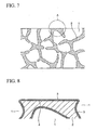
- Porous titanium usually includes continuous holes 1 opening on the surface and being connected to inner holes and a skeleton 2, as shown in Fig. 7 .
- An enlarged view of area A of the skeleton 2 of the porous titanium in Fig. 7 is shown in Fig. 8 .
- a Ti oxide layer 3 is naturally developed on a surface of the skeleton 2 of the porous titanium when the porous titanium is left in the atmosphere.
- the Ti oxide layer 3 formed on an outer skeletal surface 4 of the porous titanium is known to lower conductivity and thus increase contact resistance.
- the porous titanium is used for the air electrode and the fuel electrode of the polymer electrolyte fuel cell, it is therefore preferable to employ the porous titanium having Au coating on the surface as in the separator.
- the surface of the porous titanium has continuous holes connected to the inside at the porosity of not less than 60%.
- the Au coating is formed not only on the entire outer skeletal surface but the entire inner skeletal surface of the porous titanium. Since the Au coating is formed also on the inner skeletal surface, which is not a contact portion, an excessively large amount of costly Au is consumed.
- the polymer electrolyte fuel cell is often used as a power source of mobile devices, such as portable notebook personal computers and mobile phones, and is thus frequently subject to vibration.
- a surface of the Au coating on the outer skeletal surface of the air electrode and the fuel electrode that is in contact with the separator is often deformed or peeled off, thereby increasing the contact resistance.
- the porous titanium-made air electrode and the fuel electrode of the polymer electrolyte fuel cell have porosity and their substantial outer areas are thus extremely small. If the surface of the Au coating is deformed or peeled off, the contact resistance increases significantly as compared with ordinary air electrodes and fuel electrodes in which the Au coating is formed in the entire surface of the titanium metal.
- the present inventors have conducted research to produce porous titanium having great conductivity to be used for the air electrode and the fuel electrode of the polymer electrolyte fuel cell at a lower cost and to provide porous titanium in which Au formed on the outer skeletal surface thereof is not deformed or peeled off even if subject to wear resulting from vibration and therefore the contact resistance does not become high for a long time.
- porous titanium having great conductivity to be used for the air electrode and the fuel electrode of the polymer electrolyte fuel cell at a lower cost and to provide porous titanium in which Au formed on the outer skeletal surface thereof is not deformed or peeled off even if subject to wear resulting from vibration and therefore the contact resistance does not become high for a long time.
- the present invention has been made in view of the aforementioned knowledge, and has the following configurations.
- porous titanium having a low contact resistance and a method of producing the same according to the present invention will be described.
- the Au network is formed on the outer surface of the skeletal structure of the porous titanium body and the Ti oxide layers 3 are formed between adjacent Au cord 5 in the Au network. If the width of the Au cord 5 is too narrow, the contact resistance may become high when the porous titanium having the Au network formed on the outer skeletal surface is immersed in, for example, a sulfuric acid solution for a prolonged time.
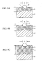
- the reference numeral 5 in Figs. 9A and 9B denotes a schematic cross section of the Au cord shown in Fig. 1 .
- the porous titanium having the Au network with the Au cord 5 of narrow width S formed on the outer skeletal surface is immersed in a sulfuric acid solution for a prolonged time, the Ti oxide layer 3 grows and increases in thickness T as shown in Fig. 9A .
- the Ti oxide layer 3 grows below the Au cord 5 from the outer circumference of the Au cord 5 so as to move the Au cord 5 up toward the surface of the Ti oxide layer 3 as shown in Fig. 9B .
- the Au cord 5 is moved upward and removed from the skeleton 2 as shown in Fig. 9C .
- the Ti oxide layer 3 now exists between the Au cord 5 and the skeleton 2.
- a diffusion bonding section 6 is eventually absorbed and disappears. As a result, the contact resistance becomes high.
- the width S of the Au cord 5 is less than 0.3 ⁇ m, the contact resistance may become higher in a relatively short time when immersed in a sulfuric acid solution. Therefore, the width S of the Au cord 5 is preferably not narrower than 0.3 ⁇ m. On the other hand, if the width S of the Au cord 5 is as large as 10 ⁇ m or more, stickiness of the Au cord 5 to the skeleton 2 reduces to easily cause separation.
- the Au network is formed on the outer surface of the skeletal structure of the porous titanium body and the adjacent Au cords 5 of the Au network are connected to each other as shown in Fig. 1 . Since the Au network is connected also to wider portions of the Au cord 5, even if there is a narrow portion a of the Au cord 5 and that portion a is separated apart from the skeleton 2, the contact resistance never becomes higher when the porous titanium is immersed in, for example, a sulfuric acid solution for a prolonged time so long as the width of the Au cord of the Au network sticking to the outer skeletal surface is in a range of 0.3 to 10 ⁇ m at least at one position.
- normal porous titanium is prepared first.
- the normal porous titanium includes the continuous holes 1 opening on a surface and being connected to inner holes as shown in Figs. 7 and 8 .
- the Ti oxide layer 3, which is a natural oxidation layer, is formed at least on the outer skeletal surface 4 of the skeleton 2.
- an Au colloid liquid in which extra-fine Au particles are suspended is applied to the Ti oxide layer 3 formed on the outer skeletal surface 4 of normal porous titanium and then dried as quickly as possible.
- an aggregate of the extra-fine Au powder deposits on the Ti oxide layer 3, which is a natural oxidation layer, to form a network structure.
- the Au colloid liquid may be applied by any method, including using a brush or an airbrush, roll printing, spray coating, transferring and pad printing. Among these, using an airbrush is the most preferable.
- the Au colloid liquid is applied on the Ti oxide layer 3, which is a natural oxidation layer, formed on the outer skeletal surface 4 of the porous titanium such that the Au cord occupies 20 to 80% of the surface area of the outer skeletal surface 4. If the application amount is less than 20%, the Au colloid liquid is applied in a granular manner rather than in a network manner. On the other hand, if the application amount is more than 80%, stickiness reduces to easily allow separation.
- the Au colloid liquid is applied to the Ti oxide layer 3, then dried in as short a time as possible, and the porous titanium is heated and kept at higher than 300°C in a vacuum atmosphere.
- oxygen included in the Ti oxide layer 3, which is a natural oxidation layer diffuses into the titanium of the skeleton 2 to form solid solution, and metallic titanium is generated on the outer surface 4 of the porous titanium.
- the Au cord 5 forms the diffusion bonding section 6 so as to firmly stick to the outer skeletal surface 4 of the titanium metal via diffusion bonding.
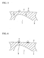
- the porous titanium is left in an oxidizing atmosphere, such as the ambient atmosphere, with the Au cord 5 firmly sticking to the outer skeletal surface 4 by diffusion bonding, the Au cord 5 adheres via diffusion bonding to the outer skeletal surface 4 of the titanium metal and the Ti oxide layer 3 is formed on the outer skeletal surface 4 at an area where no Au cord 5 exists as illustrated in the cross section of Fig. 3 . Since the Ti oxide layer 3 is formed to surround the Au cord 5, the Au cord 5 adheres still more firmly at least to the outer surface of the skeletal structure of the porous titanium body. In this manner, the porous titanium having a low contact resistance according to the present invention is obtained.
- the porous titanium having a low contact resistance produced by being left in the oxidizing atmosphere, such as the ambient atmosphere may include the Ti oxide layer 3 having insufficient thickness.
- the thickness of the Ti oxide layer 3 can be increased by heating the porous titanium having a low contact resistance produced by being left in the oxidizing atmosphere, such as the ambient atmosphere, in the ambient atmosphere.
- the porous titanium having a low contact resistance according to the present invention shown in the cross section of Fig. 3 may also be produced in the following manner.
- the Au colloid liquid in which extra-fine Au particles are suspended is applied to the Ti oxide layer 3, which is a natural oxidation layer, formed on the outer skeletal surface 4 of normal porous titanium and then dried in as short a time as possible.
- the obtained porous titanium as shown in Fig. 4 is heat-treated at the temperature of 300 to 500°C in the ambient atmosphere. In this case, when the porous titanium as shown in Fig.
- the Au cord 5 sticking to the Ti oxide layer 3, which is a natural oxidation layer is heat-treated at the temperature of 300 to 500°C in the ambient atmosphere, oxygen included in the Ti oxide layer 3, which is a natural oxidation layer, diffuses in to the titanium of the skeleton 2 to form solid solution, and metallic titanium is generated on the outer surface 4 of the porous titanium, since the Ti oxide layer 3 which is a natural oxidation layer, directly below the Au cord 5 is not in touch with the ambient air. Then the Au cord 5 forms the diffusion bonding section 6 so as to firmly stick to the outer skeletal surface 4 of the titanium metal via diffusion bonding.
- the Ti oxide layer 3 is formed to have an increased thickness on the outer skeletal surface 4 in areas where the Au colloid is not deposited and thus no Au cord 5 is provided. Since this thick Ti oxide layer 3 is formed to surround the Au cord 5, the Au code 5 adheres still more firmly at least to the outer skeletal surface 4 of the porous titanium. In this manner, the bonding structure illustrated in the cross-sectional view of Fig. 3 is provided.
- the Ti oxide layer 3 has a thickness greater than a predetermined thickness, an increase in thickness of the Ti oxide layer 3 becomes slower even if immersed in a sulfuric acid solution for a prolonged time, and thus the contact resistance never increases.
- the Ti oxide layer 3 preferably has a certain thickness after the application of the Au colloid liquid and heat-treatment.
- the thickness T of the Ti oxide layer 3 formed in the porous titanium having a low contact resistance according to the present invention is not less than 30 nm, growth of the Ti oxide layer 3 in the sulfuric acid solution becomes significantly slow and thus the contact resistance never increases even if the porous titanium is left in the sulfuric acid solution for a prolonged time.
- the Ti oxide layer 3 is initially formed by methods such as heating in the ambient air to have a thickness of greater than 150 nm, the initial resistance may disadvantageously increase.
- the width S of the Au cord 5 formed on the porous titanium having a low contact resistance according to the present invention is preferably in the range of 0.3 to 10 ⁇ m and the thickness T of the Ti oxide layer 3 after heat treatment is preferably in the range of 30 to 150 nm.
- any kind of porous titanium may be used.
- examples thereof may include: a fiber sintered body obtained by sintering titanium fiber; a powder sintered body obtained by sintering titanium powder in, for example, a usual sintering process or titanium powder; and sponge-like porous foamed titanium obtained by preparing slurry of titanium powder with, for example, a binder and a foaming agent, extending the slurry on a carrier sheet by, for example, doctor blading, heating the slurry to foam, drying the slurry to provide a green body, and then degreasing and sintering the green body.
- the sponge-like porous foamed titanium is preferably used because of its easily-controlled porosity during the production process and of a large contact area.
- the porous titanium having a low contact resistance according to the present invention contributes greatly to an improvement in performance of polymer electrolyte fuel cells in the following aspects. Since the Au cord adheres almost only to the outer skeletal surface via diffusion bonding, an amount of Au used can be reduced as compared with a case in which the Au coating is formed on the entire outer skeletal surface and the entire inner wall of the hole. Accordingly, the porous titanium having a low contact resistance may be used for the air electrode and the fuel electrode of the polymer electrolyte fuel cell at a lower cost.
- the Au cord sticking at least outer surface of the skeletal structure of the porous titanium body having a low contact resistance according to the present invention is covered with a hard Ti oxide layer, the Au cord is not deformed or peeled off even if subjected to outer pressure resulting from, for example, vibration. Furthermore, the contact resistance can be kept low for a prolonged time even if the porous titanium is immersed in a corrosive solution, such as a sulfuric acid solution.
- the following substances are prepared: titanium powder having an average particle diameter of 10 micrometer as raw powder; 10% solution of methylcellulose as a water soluble resin binder; ethylene glycol as a plasticizer; alkyl benzene sodium sulfonate as a frothering agent; and neopentane as a foaming agent.
- the obtained foamed slurry is deposited on a PET film by doctor blading at a blade gap of 0.5 mm, fed to a constant temperature and humidity chamber, and then made to foam at the temperature of 35°C and humidity of 90% for the duration of 25 minutes. Subsequently, the slurry is air-dried at the temperature of 80°C for the duration of 20 minutes to provide a sponge-like green compact.
- the compact is removed from the PET film, placed on an alumina plate, degreased at the temperature of 550°C for the duration of 180 minutes in an Ar atmosphere, and then sintered in a vacuum sintering furnace in an atmosphere of 5x10 -3 Pa, at the temperature of 1200°C for the duration of 1 hour.
- porous foamed titanium plate with porosity of 90% and thickness of 1.0 mm is obtained.
- the obtained porous foamed titanium plate is cut into pieces of 30 mm in length and 30 mm in width to prepare the porous foamed titanium material.
- An Au colloid liquid is prepared in the following process. Chloroauric acid as a main ingredient of Au particles is first dissolved in methanol so that the Au concentration becomes 4.0 mass% with gamma-aminopropyl triethoxysilane as a protecting agent precursor and dimethylamine borane as a reducing agent.
- the methanol solution in which the chloroauric acid has been dissolved is gradually added to prepare a mixed solution.
- a proper amount of dimethylamine borane as a reducing agent is added to the mixed solution. Reduction of the mixed solution is conducted while keeping the temperature of the mixed solution at 60°C and stirring the mixed solution by using a magnetic stirrer.
- the mixed solution which has undergone the reduction reaction is cooled to room temperature and then desalted by an ultrafiltration method. A proper amount of water is added to adjust the concentration. In this manner, an Au colloid liquid having concentration of 50 mass% with the water as a dispersion medium is obtained.
- the obtained Au colloid liquid was repeatedly sprayed onto the previously prepared porous foamed titanium material and dried immediately.
- the Au network was deposited to the outer skeletal surface of the porous foamed titanium material to coat the surface at the ratio shown in Table 1.
- the porous foamed titanium material was subjected to heat treatment with the Au network sticking to the outer skeletal surface thereof in the vacuum atmosphere at the temperature shown in Table 1 for the duration of 1 hour and then subjected to heat treatment in the ambient atmosphere at the temperature shown in Table 1 for the duration of 10 minutes.
- the present invention porous titanium samples 1 to 8 and comparative porous titanium samples 1 to 4 to which the Au network adheres via diffusion bonding to the outer skeletal surface of the porous foamed titanium material were produced.
- a related art porous titanium sample 1 was prepared by plating Au under normal conditions onto the surface of a previously prepared porous foamed titanium material.
- the present invention porous titanium samples 1 to 8, the comparative porous titanium samples 1 to 4 and the related art porous titanium sample 1 prepared in the reference example 1 ware each immersed in a sulfuric acid solution at the temperature of 50°C and pH of 2, kept there under the potential of 800 V (with respect to hydrogen) and taken out after 100 hours, 500 hours or 1,000 hours. Then, each of the samples was washed sufficiently with distilled water and dried in the ambient atmosphere. Subsequently, each of the present invention porous titanium samples 1 to 8, the comparative porous titanium samples 1 to 4 and the related art porous titanium sample 1 was placed between two copper plates of 50 mm in length, 50 mm in width and 10 mm in thickness and fixed there via a spring. Each of the samples was then fixed via a spring such that surface pressure between each of the samples and the copper plate was set to 1 MPa. Resistance between the copper plates was measured in this state. The obtained values are shown in Table 1 as the contact resistance values.
- Each of the present invention porous titanium samples 1 to 8, the comparative porous titanium samples 1 to 4 and the related art porous titanium sample 1 were placed between two copper plates of 50 mm in length, 50 mm in width and 10 mm in thickness and fixed there via a spring. Deflection of the spring was adjusted such that surface pressure between each of the samples and the copper plate is set to 1 MPa. Resistance between the copper plates was measured under this load and the obtained values are shown in Table 1 as the contact resistance values before the vibration test.
- each of the present invention porous titanium samples 1 to 8, the comparative porous titanium samples 1 to 4 and the related art porous titanium sample 1 were placed between two copper plates of 50 mm in length, 50 mm in width and 10 mm in thickness and fixed there via a spring. Deflection of the spring was adjusted such that surface pressure between each of the samples and the copper plate was set to 1 MPa.
- Each of the samples was placed on a vibration test facility under the load to undergo the vibration test at a frequency of 67 Hz and vibration acceleration of 70m/second 2 for the duration of 2 hours. After the vibration test, resistance between the copper plates was measured under the load at the site. The obtained values are shown in Table 1 as the contact resistance values after the vibration test.
- the present invention porous titanium samples 1 to 8 had considerably less contact resistance after the fuel cell environmental electrical connection test as compared with the related art porous titanium sample 1, and had considerably smaller variation in contact resistance both before and after the vibration test.
- the Comparative porous titanium samples 1 to 4 which are out of the range of the present invention, had unacceptable results.
- the previously obtained Au colloid liquid is diluted with ethanol so that the Au content became 4 mass%.
- the diluted Au colloid liquid was repeatedly sprayed onto the previously prepared porous foamed titanium material using an airbrush (TAB-02 manufactured by TRUSCO) at an air pressure of 0.1 MPa to coat the outer skeletal surface of the porous foamed titanium material at the ratio shown in Table 2.
- the Au colloid liquid is dried immediately to deposit the Au network to the outer skeletal surface of the porous foamed titanium material.
- the porous foamed titanium material was subjected to heat treatment with the Au network sticking to the outer skeletal surface thereof in the vacuum atmosphere at the temperature shown in Table 2 for the duration of 1 hour and then subject to heat treatment in the ambient atmosphere at the temperature shown in Table 2 for the duration of 10 minutes.
- the present invention porous titanium samples 9 to 16 to which the Au network stuck via diffusion bonding to the outer skeletal surface of the porous foamed titanium material were produced.
- the outer skeletal surfaces of the present invention porous titanium samples 9 to 16 were observed with an electron microscope and it was found that the Au network is formed in each of these outer skeletal surfaces.
- the maximum widths of the Au cord of the Au network formed on the outer skeletal surfaces of the present invention porous titanium samples 9 to 16 were measured. Further, the average thickness of the Ti oxide layer formed in the clearance between adjacent Au cords was measured. The results are shown in Table 2.
- Table 2 Porous titanium Application ratio of Au colloid (%) Conditions of heat treatment Maximum width of Au cord ( ⁇ m) Average thickness of Ti oxide layer (mn) Value of contact resistance after fuel cell environmental electrical connection test (m ⁇ . cm 2 ) Value of contact resistance (m ⁇ .
- the previously obtained Au colloid liquid was diluted with ethanol so that the Au content became 4 mass%.
- the diluted Au colloid liquid was repeatedly sprayed onto the previously prepared porous foamed titanium material using an airbrush (TAB-02 manufactured by TRUSCO) at the air pressure of 0.1 MPa to coat the outer skeletal surface of the porous foamed titanium material at the ratio shown in Table 3.
- the Au colloid liquid was dried immediately to deposit the Au network to the outer skeletal surface of the porous foamed titanium material.
- the porous foamed titanium material was subjected to heat treatment with the Au network sticking to the outer skeletal surface thereof in the ambient atmosphere at the temperature shown in Table 3 for the duration of 30 minutes. In this manner, the present invention porous titanium samples 17 to 24 to which the Au network stuck via diffusion bonding to the outer skeletal surface of the porous foamed titanium material were produced.
- the outer skeletal surfaces of the present invention porous titanium samples 17 to 24 were observed with an electron microscope and it was found that the Au network was formed in each of these outer skeletal surfaces.
- the maximum widths of the Au code of the Au network formed on the outer skeletal surfaces of the present invention porous titanium samples 17 to 24 were measured. Further, the average thickness of the Ti oxide layer formed in the clearance between adjacent Au cords was measured. The results are shown in Table 3.
- Table 3 Porous titanium Application ratio of Au colloid (%) Conditions of heat treatment Maximum width of Au cord ( ⁇ m) Average thickness of Ti Oxide layer (nm) Value of contact resistance after fuel cell environmental electrical connection test (m ⁇ . cm 2 ) Value of contact resistance (m ⁇ .
- the present invention porous titanium samples 9 to 24 have considerably smaller values of contact resistance after the fuel cell environmental electrical connection test as compared with the related art porous titanium sample 1 shown in Table 1, and have considerably smaller variation in contact resistance both before and after the vibration test.
- the porous titanium having a low contact resistance according to the present invention contributes greatly to an improvement in performance of polymer electrolyte fuel cells in the following aspects. Since the Au cord adheres almost only to the outer skeletal surface via diffusion bonding, an amount of Au used can be reduced as compared with a case in which the Au coating is formed on the entire outer skeletal surface and the entire inner wall of the hole. Accordingly, the porous titanium having a low contact resistance may be used for the air electrode and the fuel electrode of the polymer electrolyte fuel cell at a lower cost.
- the Au cord sticking at least outer surface of the skeletal structure of the porous titanium body having a low contact resistance according to the present invention is covered with a hard Ti oxide layer, the Au cord does not deform or peel off even if subjected to outer pressure resulting from, for example, vibration. Furthermore, the contact resistance can be kept low for a prolonged period of time even if the porous titanium is immersed in a corrosive solution, such as a sulfuric acid solution. Accordingly, the present invention has excellent industrial applicability.
Landscapes
- Chemical & Material Sciences (AREA)
- Engineering & Computer Science (AREA)
- Chemical Kinetics & Catalysis (AREA)
- Electrochemistry (AREA)
- General Chemical & Material Sciences (AREA)
- Manufacturing & Machinery (AREA)
- Materials Engineering (AREA)
- Sustainable Energy (AREA)
- Organic Chemistry (AREA)
- Sustainable Development (AREA)
- Composite Materials (AREA)
- Life Sciences & Earth Sciences (AREA)
- Mechanical Engineering (AREA)
- Metallurgy (AREA)
- Inorganic Chemistry (AREA)
- Ceramic Engineering (AREA)
- Fuel Cell (AREA)
- Inert Electrodes (AREA)
- Inorganic Compounds Of Heavy Metals (AREA)
- Other Surface Treatments For Metallic Materials (AREA)
- Powder Metallurgy (AREA)
Claims (3)
- Poröses Titan mit geringem Kontaktwiderstand, umfassend:einen porösen Titankörper mit einer Skelettstruktur und durchgehenden Löchern, die sich an einer äusseren Oberfläche des Titankörpers öffnen und miteinander verbunden sind, um Innenlöcher zu bilden;ein Au-Netzwerk, das auf zumindest einer äusseren Oberfläche der Skelettstruktur des Titankörpers durch Adhäsion und Diffusionsverschweissen von Au auf der äusseren Oberfläche der Skelettstruktur als kontinuierliche Netzwerkstruktur gebildet ist; undTi-Oxidschichten, die in den Zwischenräumen zwischen benachbarten Au-Korden des Au-Netzwerks gebildet sind.
- Poröses Titan mit geringem Kontaktwiderstand gemäss Anspruch 1, wobei die Breite von zumindest einem Teil der Au-Korde des Au-Netzwerks 0,3 bis 10 µm beträgt.
- Poröses Titan mit geringem Kontaktwiderstand gemäss Anspruch 1 oder 2, wobei die Dicke der Ti-Oxidschicht, die in den Zwischenräumen zwischen benachbarten Au-Korden des Au-Netzwerks gebildet ist, 30 bis 150 nm beträgt.
Applications Claiming Priority (3)
| Application Number | Priority Date | Filing Date | Title |
|---|---|---|---|
| JP2006335609 | 2006-12-13 | ||
| JP2007292956A JP5125435B2 (ja) | 2006-12-13 | 2007-11-12 | 接触抵抗の小さい多孔質チタン |
| PCT/JP2007/074038 WO2008072697A1 (ja) | 2006-12-13 | 2007-12-13 | 接触抵抗の小さい多孔質チタン |
Publications (3)
| Publication Number | Publication Date |
|---|---|
| EP2103714A1 EP2103714A1 (de) | 2009-09-23 |
| EP2103714A4 EP2103714A4 (de) | 2012-12-26 |
| EP2103714B1 true EP2103714B1 (de) | 2014-10-29 |
Family
ID=39511713
Family Applications (1)
| Application Number | Title | Priority Date | Filing Date |
|---|---|---|---|
| EP07850558.3A Not-in-force EP2103714B1 (de) | 2006-12-13 | 2007-12-13 | Poröses titan mit geringem kontaktwiderstand |
Country Status (5)
| Country | Link |
|---|---|
| US (1) | US7794853B2 (de) |
| EP (1) | EP2103714B1 (de) |
| JP (1) | JP5125435B2 (de) |
| CN (1) | CN101563482B (de) |
| WO (1) | WO2008072697A1 (de) |
Families Citing this family (1)
| Publication number | Priority date | Publication date | Assignee | Title |
|---|---|---|---|---|
| EP2314848A4 (de) | 2008-06-27 | 2017-01-25 | Sumitomo Heavy Industries, LTD. | Hybridkonstruktionsmaschine |
Family Cites Families (12)
| Publication number | Priority date | Publication date | Assignee | Title |
|---|---|---|---|---|
| US5645626A (en) * | 1990-08-10 | 1997-07-08 | Bend Research, Inc. | Composite hydrogen separation element and module |
| JP5047408B2 (ja) * | 1999-06-16 | 2012-10-10 | 新日本製鐵株式会社 | 固体高分子型燃料電池用ステンレス鋼製またはチタン製セパレータ |
| CA2300008C (en) | 1999-03-09 | 2006-07-04 | Nippon Steel Corporation | Stainless steel and titanium for solid polymer electrolyte fuel cell members |
| US6531238B1 (en) * | 2000-09-26 | 2003-03-11 | Reliant Energy Power Systems, Inc. | Mass transport for ternary reaction optimization in a proton exchange membrane fuel cell assembly and stack assembly |
| WO2003061884A1 (en) * | 2002-01-21 | 2003-07-31 | Mitsubishi Materials Kobe Tools Corporation | Surface coated cutting tool member having hard coating layer exhibiting excellent abrasion resistance in high-speed cutting, and method for forming said hard coating layer on surface of cutting tool |
| JP2004134276A (ja) * | 2002-10-11 | 2004-04-30 | Daido Steel Co Ltd | 固体高分子形燃料電池用素材及びその製造方法 |
| JP3452140B1 (ja) * | 2003-01-08 | 2003-09-29 | スガ試験機株式会社 | 水電解装置 |
| DE102004014076B3 (de) * | 2004-03-19 | 2005-12-22 | Fraunhofer-Gesellschaft zur Förderung der angewandten Forschung e.V. | Metallschaumkörper mit offenporiger Struktur sowie Verfahren zu seiner Herstellung |
| JP2006335609A (ja) | 2005-06-02 | 2006-12-14 | Gifu Prefecture | 窯業製品の加飾方法、及び窯業製品 |
| JP4895012B2 (ja) * | 2005-09-16 | 2012-03-14 | 三菱マテリアル株式会社 | 接触抵抗の小さい多孔質チタンおよびその製造方法 |
| WO2008060293A2 (en) * | 2005-12-13 | 2008-05-22 | University Of Nevada, Reno | Preparation of nano-tubular titania substrates having gold and carbon particles deposited thereon and their use in photo-electrolysis of water |
| JP4857885B2 (ja) | 2006-04-24 | 2012-01-18 | 株式会社デンソー | 表示装置 |
-
2007
- 2007-11-12 JP JP2007292956A patent/JP5125435B2/ja not_active Expired - Fee Related
- 2007-12-13 US US12/518,509 patent/US7794853B2/en not_active Expired - Fee Related
- 2007-12-13 EP EP07850558.3A patent/EP2103714B1/de not_active Not-in-force
- 2007-12-13 CN CN2007800455772A patent/CN101563482B/zh not_active Expired - Fee Related
- 2007-12-13 WO PCT/JP2007/074038 patent/WO2008072697A1/ja not_active Ceased
Also Published As
| Publication number | Publication date |
|---|---|
| JP2008169472A (ja) | 2008-07-24 |
| EP2103714A4 (de) | 2012-12-26 |
| US20100015507A1 (en) | 2010-01-21 |
| CN101563482B (zh) | 2012-02-08 |
| CN101563482A (zh) | 2009-10-21 |
| US7794853B2 (en) | 2010-09-14 |
| WO2008072697A1 (ja) | 2008-06-19 |
| JP5125435B2 (ja) | 2013-01-23 |
| EP2103714A1 (de) | 2009-09-23 |
Similar Documents
| Publication | Publication Date | Title |
|---|---|---|
| CN102473935B (zh) | 固体高分子型燃料电池隔膜用钛材及其制造方法 | |
| US20090098440A1 (en) | Microporous layer | |
| CN1961443A (zh) | 用于固体氧化物燃料电池的基于镍泡沫和毡的阳极 | |
| CN102820475A (zh) | 三元铂合金催化剂 | |
| KR20150105742A (ko) | 폴리도파민 보호 코팅을 이용한 합금촉매의 제조방법 및 이에 의하여 제조된 합금촉매 | |
| JP2005191002A (ja) | 燃料電池用ガス拡散層、電極及び膜電極接合体及びその製造方法 | |
| CN101390236A (zh) | 固体高分子型燃料电池用隔板及其制造方法 | |
| KR101970094B1 (ko) | 티탄재, 세퍼레이터, 및 고체 고분자형 연료 전지, 및 티탄재의 제조 방법 | |
| CN106030878A (zh) | 用于固体氧化物燃料电池的阴极集电器和包含所述阴极集电器的固体氧化物燃料电池 | |
| JPH01189866A (ja) | 溶融塩型燃料電池用アノードとその製造方法 | |
| KR20170054145A (ko) | 촉매, 이의 제조방법 및 이를 포함하는 연료전지 | |
| WO2005057698A1 (ja) | 燃料電池 | |
| US7794853B2 (en) | Porous titanium having low contact resistance | |
| KR100980209B1 (ko) | 건식 공정을 이용한 용융탄산염 연료전지용 다공성 금속전극의 제조방법 | |
| KR100963274B1 (ko) | 미세다공층을 포함하는 가스확산층과 그 제조방법 | |
| KR101311784B1 (ko) | 용융탄산염연료전지용 분리판의 내 부식 코팅 방법 | |
| JP2003123774A (ja) | 燃料電池用電極の製造方法、燃料電池用電極、塗布組成物、塗布組成物の製造方法、固体高分子型燃料電池、固体高分子型燃料電池の製造方法 | |
| JP6753165B2 (ja) | 固体高分子形燃料電池のセパレータ用チタン材、およびそれを用いたセパレータ | |
| JP2003308847A (ja) | 燃料電池用電極の製造方法、塗布組成物、塗布組成物の製造方法 | |
| JP2017088955A (ja) | 固体高分子形燃料電池のセパレータ用チタン材、およびそれを用いたセパレータ | |
| KR101338047B1 (ko) | 용융탄산염 연료전지용 공기극 및 이의 제조 방법 | |
| JP4895012B2 (ja) | 接触抵抗の小さい多孔質チタンおよびその製造方法 | |
| JP6206622B1 (ja) | チタン材、セパレータおよび固体高分子形燃料電池 | |
| JP4868231B2 (ja) | 接触抵抗の小さい多孔質チタンおよびその製造方法 | |
| JP2010238517A (ja) | すぐれた接面通電性を長期に亘って発揮する多孔質金属ガス拡散シートを構造部材とする固体高分子型燃料電池 |
Legal Events
| Date | Code | Title | Description |
|---|---|---|---|
| PUAI | Public reference made under article 153(3) epc to a published international application that has entered the european phase |
Free format text: ORIGINAL CODE: 0009012 |
|
| 17P | Request for examination filed |
Effective date: 20090618 |
|
| AK | Designated contracting states |
Kind code of ref document: A1 Designated state(s): AT BE BG CH CY CZ DE DK EE ES FI FR GB GR HU IE IS IT LI LT LU LV MC MT NL PL PT RO SE SI SK TR |
|
| DAX | Request for extension of the european patent (deleted) | ||
| A4 | Supplementary search report drawn up and despatched |
Effective date: 20121126 |
|
| RIC1 | Information provided on ipc code assigned before grant |
Ipc: H01M 4/86 20060101ALI20121120BHEP Ipc: H01M 4/88 20060101ALI20121120BHEP Ipc: H01M 8/02 20060101ALI20121120BHEP Ipc: C23C 24/08 20060101AFI20121120BHEP Ipc: C23C 10/60 20060101ALI20121120BHEP Ipc: C23C 28/00 20060101ALI20121120BHEP Ipc: H01M 8/10 20060101ALI20121120BHEP Ipc: C23C 10/18 20060101ALI20121120BHEP |
|
| RIC1 | Information provided on ipc code assigned before grant |
Ipc: C23C 10/18 20060101ALI20131018BHEP Ipc: H01M 4/86 20060101ALI20131018BHEP Ipc: H01M 8/10 20060101ALN20131018BHEP Ipc: C23C 28/00 20060101ALI20131018BHEP Ipc: C23C 24/08 20060101AFI20131018BHEP Ipc: H01M 8/02 20060101ALI20131018BHEP Ipc: H01M 4/88 20060101ALI20131018BHEP Ipc: C23C 10/60 20060101ALI20131018BHEP |
|
| RIC1 | Information provided on ipc code assigned before grant |
Ipc: C23C 10/60 20060101ALI20131028BHEP Ipc: H01M 4/86 20060101ALI20131028BHEP Ipc: C23C 24/08 20060101AFI20131028BHEP Ipc: C23C 10/18 20060101ALI20131028BHEP Ipc: C23C 28/00 20060101ALI20131028BHEP Ipc: H01M 4/88 20060101ALI20131028BHEP Ipc: H01M 8/02 20060101ALI20131028BHEP Ipc: H01M 8/10 20060101ALN20131028BHEP |
|
| GRAP | Despatch of communication of intention to grant a patent |
Free format text: ORIGINAL CODE: EPIDOSNIGR1 |
|
| RIC1 | Information provided on ipc code assigned before grant |
Ipc: H01M 8/10 20060101ALN20131219BHEP Ipc: C23C 10/60 20060101ALI20131219BHEP Ipc: C23C 24/08 20060101AFI20131219BHEP Ipc: C23C 28/00 20060101ALI20131219BHEP Ipc: H01M 4/88 20060101ALI20131219BHEP Ipc: H01M 8/02 20060101ALI20131219BHEP Ipc: C23C 10/18 20060101ALI20131219BHEP Ipc: H01M 4/86 20060101ALI20131219BHEP |
|
| INTG | Intention to grant announced |
Effective date: 20140109 |
|
| RIN1 | Information on inventor provided before grant (corrected) |
Inventor name: HAYASHI, TOSHIHARU Inventor name: HOSHINO, KOJI Inventor name: ORITO, KENJI Inventor name: WADA, MASAHIRO Inventor name: IZUMI, REIKO |
|
| GRAP | Despatch of communication of intention to grant a patent |
Free format text: ORIGINAL CODE: EPIDOSNIGR1 |
|
| INTG | Intention to grant announced |
Effective date: 20140522 |
|
| RIC1 | Information provided on ipc code assigned before grant |
Ipc: C23C 28/04 20060101ALI20140509BHEP Ipc: C23C 10/60 20060101ALI20140509BHEP Ipc: C23C 10/18 20060101ALI20140509BHEP Ipc: H01M 8/10 20060101ALN20140509BHEP Ipc: H01M 4/88 20060101ALI20140509BHEP Ipc: H01M 8/02 20060101ALI20140509BHEP Ipc: C23C 24/08 20060101AFI20140509BHEP Ipc: C23C 28/00 20060101ALI20140509BHEP Ipc: H01M 4/86 20060101ALI20140509BHEP |
|
| GRAS | Grant fee paid |
Free format text: ORIGINAL CODE: EPIDOSNIGR3 |
|
| GRAA | (expected) grant |
Free format text: ORIGINAL CODE: 0009210 |
|
| AK | Designated contracting states |
Kind code of ref document: B1 Designated state(s): AT BE BG CH CY CZ DE DK EE ES FI FR GB GR HU IE IS IT LI LT LU LV MC MT NL PL PT RO SE SI SK TR |
|
| REG | Reference to a national code |
Ref country code: GB Ref legal event code: FG4D |
|
| REG | Reference to a national code |
Ref country code: CH Ref legal event code: EP |
|
| REG | Reference to a national code |
Ref country code: AT Ref legal event code: REF Ref document number: 693664 Country of ref document: AT Kind code of ref document: T Effective date: 20141115 |
|
| REG | Reference to a national code |
Ref country code: IE Ref legal event code: FG4D |
|
| REG | Reference to a national code |
Ref country code: DE Ref legal event code: R096 Ref document number: 602007039078 Country of ref document: DE Effective date: 20141211 |
|
| REG | Reference to a national code |
Ref country code: AT Ref legal event code: MK05 Ref document number: 693664 Country of ref document: AT Kind code of ref document: T Effective date: 20141029 |
|
| REG | Reference to a national code |
Ref country code: NL Ref legal event code: VDEP Effective date: 20141029 |
|
| REG | Reference to a national code |
Ref country code: LT Ref legal event code: MG4D |
|
| PG25 | Lapsed in a contracting state [announced via postgrant information from national office to epo] |
Ref country code: FI Free format text: LAPSE BECAUSE OF FAILURE TO SUBMIT A TRANSLATION OF THE DESCRIPTION OR TO PAY THE FEE WITHIN THE PRESCRIBED TIME-LIMIT Effective date: 20141029 Ref country code: ES Free format text: LAPSE BECAUSE OF FAILURE TO SUBMIT A TRANSLATION OF THE DESCRIPTION OR TO PAY THE FEE WITHIN THE PRESCRIBED TIME-LIMIT Effective date: 20141029 Ref country code: NL Free format text: LAPSE BECAUSE OF FAILURE TO SUBMIT A TRANSLATION OF THE DESCRIPTION OR TO PAY THE FEE WITHIN THE PRESCRIBED TIME-LIMIT Effective date: 20141029 Ref country code: IS Free format text: LAPSE BECAUSE OF FAILURE TO SUBMIT A TRANSLATION OF THE DESCRIPTION OR TO PAY THE FEE WITHIN THE PRESCRIBED TIME-LIMIT Effective date: 20150228 Ref country code: LT Free format text: LAPSE BECAUSE OF FAILURE TO SUBMIT A TRANSLATION OF THE DESCRIPTION OR TO PAY THE FEE WITHIN THE PRESCRIBED TIME-LIMIT Effective date: 20141029 Ref country code: PT Free format text: LAPSE BECAUSE OF FAILURE TO SUBMIT A TRANSLATION OF THE DESCRIPTION OR TO PAY THE FEE WITHIN THE PRESCRIBED TIME-LIMIT Effective date: 20150302 |
|
| PG25 | Lapsed in a contracting state [announced via postgrant information from national office to epo] |
Ref country code: LV Free format text: LAPSE BECAUSE OF FAILURE TO SUBMIT A TRANSLATION OF THE DESCRIPTION OR TO PAY THE FEE WITHIN THE PRESCRIBED TIME-LIMIT Effective date: 20141029 Ref country code: SE Free format text: LAPSE BECAUSE OF FAILURE TO SUBMIT A TRANSLATION OF THE DESCRIPTION OR TO PAY THE FEE WITHIN THE PRESCRIBED TIME-LIMIT Effective date: 20141029 Ref country code: CY Free format text: LAPSE BECAUSE OF FAILURE TO SUBMIT A TRANSLATION OF THE DESCRIPTION OR TO PAY THE FEE WITHIN THE PRESCRIBED TIME-LIMIT Effective date: 20141029 Ref country code: AT Free format text: LAPSE BECAUSE OF FAILURE TO SUBMIT A TRANSLATION OF THE DESCRIPTION OR TO PAY THE FEE WITHIN THE PRESCRIBED TIME-LIMIT Effective date: 20141029 Ref country code: PL Free format text: LAPSE BECAUSE OF FAILURE TO SUBMIT A TRANSLATION OF THE DESCRIPTION OR TO PAY THE FEE WITHIN THE PRESCRIBED TIME-LIMIT Effective date: 20141029 Ref country code: GR Free format text: LAPSE BECAUSE OF FAILURE TO SUBMIT A TRANSLATION OF THE DESCRIPTION OR TO PAY THE FEE WITHIN THE PRESCRIBED TIME-LIMIT Effective date: 20150130 |
|
| PG25 | Lapsed in a contracting state [announced via postgrant information from national office to epo] |
Ref country code: BE Free format text: LAPSE BECAUSE OF NON-PAYMENT OF DUE FEES Effective date: 20141231 |
|
| REG | Reference to a national code |
Ref country code: DE Ref legal event code: R097 Ref document number: 602007039078 Country of ref document: DE |
|
| PG25 | Lapsed in a contracting state [announced via postgrant information from national office to epo] |
Ref country code: LU Free format text: LAPSE BECAUSE OF FAILURE TO SUBMIT A TRANSLATION OF THE DESCRIPTION OR TO PAY THE FEE WITHIN THE PRESCRIBED TIME-LIMIT Effective date: 20141213 Ref country code: SK Free format text: LAPSE BECAUSE OF FAILURE TO SUBMIT A TRANSLATION OF THE DESCRIPTION OR TO PAY THE FEE WITHIN THE PRESCRIBED TIME-LIMIT Effective date: 20141029 Ref country code: EE Free format text: LAPSE BECAUSE OF FAILURE TO SUBMIT A TRANSLATION OF THE DESCRIPTION OR TO PAY THE FEE WITHIN THE PRESCRIBED TIME-LIMIT Effective date: 20141029 Ref country code: DK Free format text: LAPSE BECAUSE OF FAILURE TO SUBMIT A TRANSLATION OF THE DESCRIPTION OR TO PAY THE FEE WITHIN THE PRESCRIBED TIME-LIMIT Effective date: 20141029 Ref country code: RO Free format text: LAPSE BECAUSE OF FAILURE TO SUBMIT A TRANSLATION OF THE DESCRIPTION OR TO PAY THE FEE WITHIN THE PRESCRIBED TIME-LIMIT Effective date: 20141029 Ref country code: CZ Free format text: LAPSE BECAUSE OF FAILURE TO SUBMIT A TRANSLATION OF THE DESCRIPTION OR TO PAY THE FEE WITHIN THE PRESCRIBED TIME-LIMIT Effective date: 20141029 |
|
| REG | Reference to a national code |
Ref country code: CH Ref legal event code: PL |
|
| PG25 | Lapsed in a contracting state [announced via postgrant information from national office to epo] |
Ref country code: IT Free format text: LAPSE BECAUSE OF FAILURE TO SUBMIT A TRANSLATION OF THE DESCRIPTION OR TO PAY THE FEE WITHIN THE PRESCRIBED TIME-LIMIT Effective date: 20141029 |
|
| PLBE | No opposition filed within time limit |
Free format text: ORIGINAL CODE: 0009261 |
|
| STAA | Information on the status of an ep patent application or granted ep patent |
Free format text: STATUS: NO OPPOSITION FILED WITHIN TIME LIMIT |
|
| GBPC | Gb: european patent ceased through non-payment of renewal fee |
Effective date: 20150129 |
|
| REG | Reference to a national code |
Ref country code: IE Ref legal event code: MM4A |
|
| REG | Reference to a national code |
Ref country code: FR Ref legal event code: ST Effective date: 20150831 |
|
| 26N | No opposition filed |
Effective date: 20150730 |
|
| PG25 | Lapsed in a contracting state [announced via postgrant information from national office to epo] |
Ref country code: GB Free format text: LAPSE BECAUSE OF NON-PAYMENT OF DUE FEES Effective date: 20150129 Ref country code: CH Free format text: LAPSE BECAUSE OF NON-PAYMENT OF DUE FEES Effective date: 20141231 Ref country code: LI Free format text: LAPSE BECAUSE OF NON-PAYMENT OF DUE FEES Effective date: 20141231 Ref country code: IE Free format text: LAPSE BECAUSE OF NON-PAYMENT OF DUE FEES Effective date: 20141213 |
|
| PG25 | Lapsed in a contracting state [announced via postgrant information from national office to epo] |
Ref country code: FR Free format text: LAPSE BECAUSE OF NON-PAYMENT OF DUE FEES Effective date: 20141231 |
|
| PG25 | Lapsed in a contracting state [announced via postgrant information from national office to epo] |
Ref country code: SI Free format text: LAPSE BECAUSE OF FAILURE TO SUBMIT A TRANSLATION OF THE DESCRIPTION OR TO PAY THE FEE WITHIN THE PRESCRIBED TIME-LIMIT Effective date: 20141029 |
|
| PG25 | Lapsed in a contracting state [announced via postgrant information from national office to epo] |
Ref country code: BG Free format text: LAPSE BECAUSE OF FAILURE TO SUBMIT A TRANSLATION OF THE DESCRIPTION OR TO PAY THE FEE WITHIN THE PRESCRIBED TIME-LIMIT Effective date: 20141029 Ref country code: MC Free format text: LAPSE BECAUSE OF FAILURE TO SUBMIT A TRANSLATION OF THE DESCRIPTION OR TO PAY THE FEE WITHIN THE PRESCRIBED TIME-LIMIT Effective date: 20141029 |
|
| PG25 | Lapsed in a contracting state [announced via postgrant information from national office to epo] |
Ref country code: TR Free format text: LAPSE BECAUSE OF FAILURE TO SUBMIT A TRANSLATION OF THE DESCRIPTION OR TO PAY THE FEE WITHIN THE PRESCRIBED TIME-LIMIT Effective date: 20141029 Ref country code: MT Free format text: LAPSE BECAUSE OF FAILURE TO SUBMIT A TRANSLATION OF THE DESCRIPTION OR TO PAY THE FEE WITHIN THE PRESCRIBED TIME-LIMIT Effective date: 20141029 Ref country code: HU Free format text: LAPSE BECAUSE OF FAILURE TO SUBMIT A TRANSLATION OF THE DESCRIPTION OR TO PAY THE FEE WITHIN THE PRESCRIBED TIME-LIMIT; INVALID AB INITIO Effective date: 20071213 |
|
| PGFP | Annual fee paid to national office [announced via postgrant information from national office to epo] |
Ref country code: DE Payment date: 20211210 Year of fee payment: 15 |
|
| REG | Reference to a national code |
Ref country code: DE Ref legal event code: R119 Ref document number: 602007039078 Country of ref document: DE |
|
| PG25 | Lapsed in a contracting state [announced via postgrant information from national office to epo] |
Ref country code: DE Free format text: LAPSE BECAUSE OF NON-PAYMENT OF DUE FEES Effective date: 20230701 |