EP2103773A2 - Dispositif de protection, notamment moustiquaire - Google Patents
Dispositif de protection, notamment moustiquaire Download PDFInfo
- Publication number
- EP2103773A2 EP2103773A2 EP09001480A EP09001480A EP2103773A2 EP 2103773 A2 EP2103773 A2 EP 2103773A2 EP 09001480 A EP09001480 A EP 09001480A EP 09001480 A EP09001480 A EP 09001480A EP 2103773 A2 EP2103773 A2 EP 2103773A2
- Authority
- EP
- European Patent Office
- Prior art keywords
- motor
- shaft
- closing
- frame
- legs
- Prior art date
- Legal status (The legal status is an assumption and is not a legal conclusion. Google has not performed a legal analysis and makes no representation as to the accuracy of the status listed.)
- Withdrawn
Links
- 239000004744 fabric Substances 0.000 claims description 17
- 238000007789 sealing Methods 0.000 claims description 2
- 230000001681 protective effect Effects 0.000 description 12
- 241000238631 Hexapoda Species 0.000 description 5
- 241000255925 Diptera Species 0.000 description 4
- 230000033001 locomotion Effects 0.000 description 4
- 238000004804 winding Methods 0.000 description 3
- 230000004888 barrier function Effects 0.000 description 2
- 238000010276 construction Methods 0.000 description 2
- 238000009434 installation Methods 0.000 description 2
- 230000003213 activating effect Effects 0.000 description 1
- 238000005452 bending Methods 0.000 description 1
- 230000005540 biological transmission Effects 0.000 description 1
- 230000001419 dependent effect Effects 0.000 description 1
- 238000011161 development Methods 0.000 description 1
- 230000018109 developmental process Effects 0.000 description 1
- 238000005538 encapsulation Methods 0.000 description 1
- 239000000463 material Substances 0.000 description 1
- 230000009347 mechanical transmission Effects 0.000 description 1
- 238000004806 packaging method and process Methods 0.000 description 1
- 125000006850 spacer group Chemical group 0.000 description 1
- 230000001360 synchronised effect Effects 0.000 description 1
- 230000007704 transition Effects 0.000 description 1
- 230000001960 triggered effect Effects 0.000 description 1
Images


Classifications
-
- E—FIXED CONSTRUCTIONS
- E06—DOORS, WINDOWS, SHUTTERS, OR ROLLER BLINDS IN GENERAL; LADDERS
- E06B—FIXED OR MOVABLE CLOSURES FOR OPENINGS IN BUILDINGS, VEHICLES, FENCES OR LIKE ENCLOSURES IN GENERAL, e.g. DOORS, WINDOWS, BLINDS, GATES
- E06B9/00—Screening or protective devices for wall or similar openings, with or without operating or securing mechanisms; Closures of similar construction
- E06B9/52—Devices affording protection against insects, e.g. fly screens; Mesh windows for other purposes
- E06B9/54—Roller fly screens
-
- E—FIXED CONSTRUCTIONS
- E06—DOORS, WINDOWS, SHUTTERS, OR ROLLER BLINDS IN GENERAL; LADDERS
- E06B—FIXED OR MOVABLE CLOSURES FOR OPENINGS IN BUILDINGS, VEHICLES, FENCES OR LIKE ENCLOSURES IN GENERAL, e.g. DOORS, WINDOWS, BLINDS, GATES
- E06B9/00—Screening or protective devices for wall or similar openings, with or without operating or securing mechanisms; Closures of similar construction
- E06B9/56—Operating, guiding or securing devices or arrangements for roll-type closures; Spring drums; Tape drums; Counterweighting arrangements therefor
- E06B9/58—Guiding devices
-
- E—FIXED CONSTRUCTIONS
- E06—DOORS, WINDOWS, SHUTTERS, OR ROLLER BLINDS IN GENERAL; LADDERS
- E06B—FIXED OR MOVABLE CLOSURES FOR OPENINGS IN BUILDINGS, VEHICLES, FENCES OR LIKE ENCLOSURES IN GENERAL, e.g. DOORS, WINDOWS, BLINDS, GATES
- E06B9/00—Screening or protective devices for wall or similar openings, with or without operating or securing mechanisms; Closures of similar construction
- E06B9/56—Operating, guiding or securing devices or arrangements for roll-type closures; Spring drums; Tape drums; Counterweighting arrangements therefor
- E06B9/68—Operating devices or mechanisms, e.g. with electric drive
-
- E—FIXED CONSTRUCTIONS
- E06—DOORS, WINDOWS, SHUTTERS, OR ROLLER BLINDS IN GENERAL; LADDERS
- E06B—FIXED OR MOVABLE CLOSURES FOR OPENINGS IN BUILDINGS, VEHICLES, FENCES OR LIKE ENCLOSURES IN GENERAL, e.g. DOORS, WINDOWS, BLINDS, GATES
- E06B9/00—Screening or protective devices for wall or similar openings, with or without operating or securing mechanisms; Closures of similar construction
- E06B9/52—Devices affording protection against insects, e.g. fly screens; Mesh windows for other purposes
- E06B9/54—Roller fly screens
- E06B2009/543—Horizontally moving screens
Definitions
- the invention relates to a protective device, which can be used in particular as a fly screen and / or as a light curtain, according to the preamble of claim 1.
- Manually operated fly screens are well known.
- a shutter with a manually operated fly screen, which consists of a wound on a roll, tensioned fabric that can be manually opened and closed by a correspondingly guided locking rail.
- the invention has the object of developing a protective device of the type mentioned in such a way that the protective device automatically opens and closes to keep the time duration during which the protective device is opened as low as possible.
- the tissue can be divided centrally or eccentrically vertically, wherein both parts of the fabric on different, preferably opposite configured as a hollow cylinder shafts or rollers can be wound.
- the tissue on rotatably mounted cylinder up and is unwound which are centrally penetrated by one of the waves in order to make optimum use of the available space as possible.
- the locking rails are driven in opposite directions via one or more toothed belts, which allows a compact and simple construction.
- other mechanical transmission means such as chains or belts are suitable.
- the fabric is preferably stretched by acting on the hollow cylinder coil springs, creating a compact design of the frame is formed and the fabric is held evenly flat.
- the locking rails are guided in parallel by two opposing synchronously driven toothed belts, namely namely a uniform winding and unrolling of the fabric is possible.
- the guide is improved when the opposite toothed belt of gears are synchronously driven by a shaft.
- a compact embodiment which is reflected in an overall low depth, is achieved in particular by a motor or motors arranged at right angles to a shaft and in that both the drive of the closing rails and the winding of the fabric take place through the shafts.
- the openings of the guide grooves for the tissue in the legs can be kept so small that no insects get through between frame and trade and no brush strips are needed.
- a preferred embodiment is constructed so that the depth of the fly screen frame or the structure of the window or door is sized as small as possible and thus can be mounted in many cases between the spacer frame of the roller shutter guides, without affecting the function of the shutter.
- the low circumferential depth of the fly screen frame is achieved in particular by the arrangement of the waves in the hollow cylinders and by the vertical arrangement of the motor with electronics perpendicular to the waves.
- the motor or motors may be controlled by a sensor through which the fabric is opened when a door or window is closed.
- the tissue can be opened manually by means of a switch or closed.
- this may be accomplished by a sensor that opens the fly screen when an object is detected in the vicinity of the fly screen and closes the fly screen when there is no object in the environment.
- the operation of the fly screen can thus be triggered, for example, by push button, motion or by the interruption of the light beam of a light barrier, in which case the fly screen opens automatically and closes automatically after passing or after leaving the sensor area after a lesser time.
- the fly screen opens controlled by a sensor automatically.
- the view to the outside is not affected when the door or window is closed.
- the service life of the mesh also increases considerably, as it is protected when rolled up and thus less exposed to light, rain and dirt.
- Another advantage is that the fabric does not have to be disassembled during the winter months.
- the frame consists of four legs.
- the fly screen shown in the embodiment is constructed so that the four legs can be plugged together on site with little effort and mounted on the door intended for this purpose.
- the protection device can be sent in a handy and space-saving packaging to the customer.
- the motor of the fly screen is preferably operated with low voltage of, for example 12-24 volts, by an external power supply, a flush-mounted transformer or an integrated power supply provided.
- the flush-mounted transformer system can be connected to a rocker switch and, if the function of the fly screen is not needed, disconnected from the power supply.
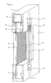
- protection device 1 is externally or internally fixedly mounted on a door 2, so that the door 2 is completely covered by the protection device 1, as well as for separating between two rooms, for. B. be firmly mounted in kitchens or butcheries in the commercial sector.
- the protection device 1 consists of a tissue 8 having a hole size through which insects can not pass.
- the fabric 8 can also be made of a material that prevents the sun's UV light from entering the interior of the room. Consequently, the door 2, for example, on a residential house, caravan, motor home and in business premises, completely covered by the protection device 1.
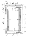
- the protective device 1 consists of a rectangular frame 3, which is the entire surface, mounted on the outside of the door 2.
- the frame 3 can also be mounted on the inside, when the door 2 rises to the outside.
- the frame 3 comprises two vertically extending legs 4 and 5 and two horizontally aligned legs 6 and 7, which are fixedly connected at a right angle to each other by means of plug connection.
- the the FIGS. 1 to 7 Underlying protection device 1 also has two locking rails 9, which are held movable between the two horizontally extending legs 6 and 7 in a respective incorporated in this guide groove 13.
- Each of the closing rails 9 accordingly runs in two guide grooves 13, each of which receives one of the closing rails 9, which are incorporated in the horizontal legs 6 and 7.
- the guide grooves 13 are aligned with each other and are laterally offset from the adjacent guide grooves 13, in which the second locking rail 9 is movable.
- the two locking rails 9 are in the closed state overlapping and close to each other.
- Suitable sensors 19 are light barriers, infrared sensors or distance sensors.
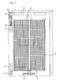
- the motor 14 drives on the drive shaft 30 on which a gear 15 is fixed, a circulating toothed belt 16 at. With the toothed belt 16, a second drive shaft 30 is synchronously set in rotation on the opposite side via a gear 15.
- the drive shafts 30, 31 drive via a plug connection to the shafts 11 and 12, and thus extend in the two vertical legs 4 and 5.
- the drive shafts 30 and 31 are held in bearings 28.
- the shaft 11 is additionally mounted in the corner angle above again by means of a slide rail 23.
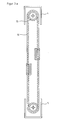
- FIG. 3a the arrangement of the upper toothed belt 16 can be taken from a center-closing protection device.
- the arrangement of the lower toothed belt 17 is identical.
- the section shows the gears 15 and the toothed belt 16.
- On the revolving toothed belt 16 each one of the toothed belts 16 and 17 are mounted on two opposite sides.
- the two closing rails 9 are moved in activating the toothed belt 16 of this in the same direction, namely either to open the protection device 1 in the direction of the shaft 11 or 12 or when the protective device 1 is opened by the shaft 11 and 12 in the closed position.
- FIG. 3b is the arrangement of the upper toothed belt 16, 16.1 an off-center closing protection device are removed.
- the two upper toothed belts 16, 16.1 and the lower toothed belts 17, 17.1 are tensioned with abutment 31.
- the toothed belts 16, 16.1 or 17, 17.1 are synchronously set in rotation via gears 15 and the shafts 11 and 12, respectively.
- Each belt pair 16, 17 and timing belt pair 16.1, 17.1 are each driven by a motor 14.
- FIG. 4 the engine 14 and the sensor 19 are shown.
- this symmetrical structure is a parallel guide the locking rails 9 and thus the optimal winding and unwinding of the fabric 8 on a hollow cylinder 27 which is connected to one of the shafts 11 or 12, guaranteed.
- stiffening profiles can be used in the legs 4 and 5.
- FIG. 5 can the space-saving design of the shaft 11 are removed with the hollow cylinder 27.
- the shaft 11 passes completely through the hollow cylinder 27 so that the synchronous rotation transmission of the shaft 11 between the upper toothed belt 16 and under the toothed belt 17 is ensured.
- the hollow cylinder 27 is connected to the shaft 11, so that the rotation of the shaft 11 is transmitted to the hollow cylinder 27.
- the fabric 8 is thus wound up or unwound onto the outer circumferential surface of the hollow cylinder 27.
- a spiral spring 18 is provided which is non-rotatably connected with a free end with the shaft 11 and the other free end with the inner circumferential surface of the hollow cylinder 27.
- FIG. 6 is the lateral offset of the two closing rails 9 receiving guide grooves 13 to recognize and that the two locking rails 9 in the closed position of the protective device 1 overlapping each other, namely abut against a common bearing surface 26.
- the possibly existing air gap between the abutment surfaces 26 can be closed by an outwardly facing sealing lip 20, so that insects between the contact surfaces 26 of the two locking rails 9 can not pass.
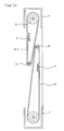
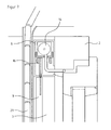
- FIG. 7 It is shown how the frame 3 of the protective device 1 is mounted on the outside of the door 2 and while the door 2 closing shutter 29 is not hindered in its movement.
- the frame 3 is in this case in the available space available between the outside of the door 2 and the shutter 29 is present.
Landscapes
- Engineering & Computer Science (AREA)
- Structural Engineering (AREA)
- Architecture (AREA)
- Civil Engineering (AREA)
- Life Sciences & Earth Sciences (AREA)
- Insects & Arthropods (AREA)
- Pest Control & Pesticides (AREA)
- Operating, Guiding And Securing Of Roll- Type Closing Members (AREA)
- Power-Operated Mechanisms For Wings (AREA)
Applications Claiming Priority (1)
| Application Number | Priority Date | Filing Date | Title |
|---|---|---|---|
| DE200810015020 DE102008015020A1 (de) | 2008-03-19 | 2008-03-19 | Schutzvorrichtung, insbesondere Fliegengitter |
Publications (2)
| Publication Number | Publication Date |
|---|---|
| EP2103773A2 true EP2103773A2 (fr) | 2009-09-23 |
| EP2103773A3 EP2103773A3 (fr) | 2012-03-14 |
Family
ID=40599912
Family Applications (1)
| Application Number | Title | Priority Date | Filing Date |
|---|---|---|---|
| EP09001480A Withdrawn EP2103773A3 (fr) | 2008-03-19 | 2009-02-04 | Dispositif de protection, notamment moustiquaire |
Country Status (2)
| Country | Link |
|---|---|
| EP (1) | EP2103773A3 (fr) |
| DE (1) | DE102008015020A1 (fr) |
Cited By (6)
| Publication number | Priority date | Publication date | Assignee | Title |
|---|---|---|---|---|
| CN103603590A (zh) * | 2013-12-02 | 2014-02-26 | 哈尔滨森鹰窗业股份有限公司 | 可以快速拆卸安装的纱窗 |
| US20180305976A1 (en) * | 2015-11-24 | 2018-10-25 | Metaco, Inc. | Electric screen device |
| CN108756701A (zh) * | 2018-05-04 | 2018-11-06 | 珠海市杰理科技股份有限公司 | 防蚊虫纱窗和防蚊虫方法 |
| JP2020058829A (ja) * | 2019-12-19 | 2020-04-16 | 株式会社メタコ | 電動スクリーン装置 |
| JP2020058830A (ja) * | 2019-12-19 | 2020-04-16 | 株式会社メタコ | 電動スクリーン装置 |
| EP4047172A1 (fr) * | 2021-02-17 | 2022-08-24 | Hendrikus Antonius Maria Bouhuis | Dispositif de commande de porte moustiquaire pour l'ouverture et la fermeture automatiques d'une porte moustiquaire |
Citations (1)
| Publication number | Priority date | Publication date | Assignee | Title |
|---|---|---|---|---|
| DE102004054148A1 (de) | 2004-11-08 | 2006-05-24 | Exte-Extrudertechnik Gmbh | Kombination eines Rolladen mit einem Fliegengitter |
Family Cites Families (9)
| Publication number | Priority date | Publication date | Assignee | Title |
|---|---|---|---|---|
| SE457976B (sv) * | 1986-01-20 | 1989-02-13 | Nomafa Ab | Horisontalloepande rullport |
| DE4227328C1 (de) * | 1992-08-18 | 1993-10-07 | Seuster Adolf Gmbh | Rolltor |
| US5671790A (en) * | 1996-01-24 | 1997-09-30 | V. Kann Rasmussen Industri A/S | Screening device for a wall opening |
| IT1314558B1 (it) * | 2000-12-04 | 2002-12-18 | Flexso S R L | Dispositivo di azionamento del movimento verticale od orizzontale pertende da sole, zanzariere, tapparelle, ecc. |
| DE20210855U1 (de) * | 2002-07-18 | 2003-05-28 | Tussinger, Philipp, 76275 Ettlingen | Rollovorrichtung |
| DE10319893B4 (de) * | 2003-04-28 | 2015-11-19 | Brose Fahrzeugteile Gmbh & Co. Kommanditgesellschaft, Coburg | Steuereinrichtung für Sonnenschutzrollos und verstellbare Fensterscheiben von Kraftfahrzeugen |
| DE102004032769A1 (de) * | 2004-07-06 | 2006-02-09 | Michael Mayr | In Isolierglasscheibe integrierter Rollomechanismus für geneigte Fenster |
| CN101336330B (zh) * | 2005-12-12 | 2012-10-31 | 澳大利亚森特股份有限公司 | 横拉卷式纱网组件 |
| WO2008023973A1 (fr) * | 2006-08-23 | 2008-02-28 | Hendrikus Lambertus Jacobs | Système de store à rouleaux |
-
2008
- 2008-03-19 DE DE200810015020 patent/DE102008015020A1/de not_active Ceased
-
2009
- 2009-02-04 EP EP09001480A patent/EP2103773A3/fr not_active Withdrawn
Patent Citations (1)
| Publication number | Priority date | Publication date | Assignee | Title |
|---|---|---|---|---|
| DE102004054148A1 (de) | 2004-11-08 | 2006-05-24 | Exte-Extrudertechnik Gmbh | Kombination eines Rolladen mit einem Fliegengitter |
Cited By (10)
| Publication number | Priority date | Publication date | Assignee | Title |
|---|---|---|---|---|
| CN103603590A (zh) * | 2013-12-02 | 2014-02-26 | 哈尔滨森鹰窗业股份有限公司 | 可以快速拆卸安装的纱窗 |
| CN103603590B (zh) * | 2013-12-02 | 2016-01-20 | 哈尔滨森鹰窗业股份有限公司 | 可以快速拆卸安装的纱窗 |
| US20180305976A1 (en) * | 2015-11-24 | 2018-10-25 | Metaco, Inc. | Electric screen device |
| EP3382135A4 (fr) * | 2015-11-24 | 2020-03-11 | Metaco Inc. | Dispositif de protection électrique |
| US10822868B2 (en) | 2015-11-24 | 2020-11-03 | Metaco, Inc. | Electric screen device |
| EP3893382A1 (fr) * | 2015-11-24 | 2021-10-13 | Metaco Inc. | Écran de protection électrique |
| CN108756701A (zh) * | 2018-05-04 | 2018-11-06 | 珠海市杰理科技股份有限公司 | 防蚊虫纱窗和防蚊虫方法 |
| JP2020058829A (ja) * | 2019-12-19 | 2020-04-16 | 株式会社メタコ | 電動スクリーン装置 |
| JP2020058830A (ja) * | 2019-12-19 | 2020-04-16 | 株式会社メタコ | 電動スクリーン装置 |
| EP4047172A1 (fr) * | 2021-02-17 | 2022-08-24 | Hendrikus Antonius Maria Bouhuis | Dispositif de commande de porte moustiquaire pour l'ouverture et la fermeture automatiques d'une porte moustiquaire |
Also Published As
| Publication number | Publication date |
|---|---|
| EP2103773A3 (fr) | 2012-03-14 |
| DE102008015020A1 (de) | 2009-10-01 |
Similar Documents
| Publication | Publication Date | Title |
|---|---|---|
| DE69403132T2 (de) | Motorangetriebener Rolladen | |
| DE69637425T2 (de) | Abdichtbare Abdeckung | |
| EP0224581B1 (fr) | Volet roulant | |
| EP2103773A2 (fr) | Dispositif de protection, notamment moustiquaire | |
| DE3936343C2 (fr) | ||
| DE202014101850U1 (de) | System zum rotierenden Antreiben einer Aufrolltrommel und aufrollbarer Verschlussschirm | |
| EP2395195A2 (fr) | Porte additionelle, notamment porte moustiquaire, avec un mécanisme de fermeture automatique | |
| DE69603590T2 (de) | Hubtor mit sicherheitssystem | |
| DE102009004976B4 (de) | Rolltoranlage | |
| DE4034614C2 (fr) | ||
| DE19707607C2 (de) | Einrichtung mit einem verstellbaren Organ zum Schutz gegen Licht und/oder Witterung und/oder Einbruch und/oder zum Umlenken von Licht | |
| EP1223299A2 (fr) | Store enroulable, en particulier moustiquaire | |
| DE4003359A1 (de) | Rolltor mit einem waermegedaemmt und/oder gepanzerten torblatt-behang | |
| EP2896763B1 (fr) | Dispositif de protection pivotant extensible | |
| DE19805272B4 (de) | Einrichtung zum Schützen, Abdecken, Verschließen, Abtrennen o. dgl. Abgrenzen von Bereichen | |
| AT519889B1 (de) | Rollgitter-Toranlage | |
| DE4100609A1 (de) | Antriebsvorrichtung fuer eine rollflaeche | |
| EP1857628B1 (fr) | Porte roulante | |
| DE4438019C1 (de) | Abdeckvorrichtung, insbesondere für Wechselverkehrszeichen | |
| DE69703621T2 (de) | Schliessvorrichtung für rollos, markisen und dergleichen | |
| DE4220434A1 (de) | Schallschutzvorrichtung für Gebäude | |
| DE102007002075B4 (de) | Rollladenkasten mit einer Walze und einem darauf gewickelten Rollladen | |
| DE102005013743B4 (de) | Vorrichtung zum Freigeben eines Fluchtweges | |
| DE102021102866A1 (de) | Rolltoranlage | |
| DE3000112A1 (de) | Einrichtung zur innenausstattung |
Legal Events
| Date | Code | Title | Description |
|---|---|---|---|
| PUAI | Public reference made under article 153(3) epc to a published international application that has entered the european phase |
Free format text: ORIGINAL CODE: 0009012 |
|
| AK | Designated contracting states |
Kind code of ref document: A2 Designated state(s): AT BE BG CH CY CZ DE DK EE ES FI FR GB GR HR HU IE IS IT LI LT LU LV MC MK MT NL NO PL PT RO SE SI SK TR |
|
| AX | Request for extension of the european patent |
Extension state: AL BA RS |
|
| PUAL | Search report despatched |
Free format text: ORIGINAL CODE: 0009013 |
|
| AK | Designated contracting states |
Kind code of ref document: A3 Designated state(s): AT BE BG CH CY CZ DE DK EE ES FI FR GB GR HR HU IE IS IT LI LT LU LV MC MK MT NL NO PL PT RO SE SI SK TR |
|
| AX | Request for extension of the european patent |
Extension state: AL BA RS |
|
| RIC1 | Information provided on ipc code assigned before grant |
Ipc: E06B 9/68 20060101ALI20120208BHEP Ipc: E06B 9/58 20060101ALI20120208BHEP Ipc: E06B 9/54 20060101AFI20120208BHEP |
|
| AKY | No designation fees paid | ||
| REG | Reference to a national code |
Ref country code: DE Ref legal event code: R108 |
|
| REG | Reference to a national code |
Ref country code: DE Ref legal event code: R108 Effective date: 20121121 |
|
| STAA | Information on the status of an ep patent application or granted ep patent |
Free format text: STATUS: THE APPLICATION IS DEEMED TO BE WITHDRAWN |
|
| 18D | Application deemed to be withdrawn |
Effective date: 20120915 |