EP2103779A1 - Verfahren und Vorrichtungen zur Korrektur des Verdrehwinkels einer Gasturbinenschaufel - Google Patents
Verfahren und Vorrichtungen zur Korrektur des Verdrehwinkels einer Gasturbinenschaufel Download PDFInfo
- Publication number
- EP2103779A1 EP2103779A1 EP09250371A EP09250371A EP2103779A1 EP 2103779 A1 EP2103779 A1 EP 2103779A1 EP 09250371 A EP09250371 A EP 09250371A EP 09250371 A EP09250371 A EP 09250371A EP 2103779 A1 EP2103779 A1 EP 2103779A1
- Authority
- EP
- European Patent Office
- Prior art keywords
- blade
- tip
- root
- twist angle
- angular load
- Prior art date
- Legal status (The legal status is an assumption and is not a legal conclusion. Google has not performed a legal analysis and makes no representation as to the accuracy of the status listed.)
- Withdrawn
Links
Images




Classifications
-
- F—MECHANICAL ENGINEERING; LIGHTING; HEATING; WEAPONS; BLASTING
- F01—MACHINES OR ENGINES IN GENERAL; ENGINE PLANTS IN GENERAL; STEAM ENGINES
- F01D—NON-POSITIVE DISPLACEMENT MACHINES OR ENGINES, e.g. STEAM TURBINES
- F01D5/00—Blades; Blade-carrying members; Heating, heat-insulating, cooling or antivibration means on the blades or the members
- F01D5/005—Repairing methods or devices
-
- B—PERFORMING OPERATIONS; TRANSPORTING
- B21—MECHANICAL METAL-WORKING WITHOUT ESSENTIALLY REMOVING MATERIAL; PUNCHING METAL
- B21D—WORKING OR PROCESSING OF SHEET METAL OR METAL TUBES, RODS OR PROFILES WITHOUT ESSENTIALLY REMOVING MATERIAL; PUNCHING METAL
- B21D3/00—Straightening or restoring form of metal rods, metal tubes, metal profiles, or specific articles made therefrom, whether or not in combination with sheet metal parts
- B21D3/14—Recontouring
-
- B—PERFORMING OPERATIONS; TRANSPORTING
- B23—MACHINE TOOLS; METAL-WORKING NOT OTHERWISE PROVIDED FOR
- B23P—METAL-WORKING NOT OTHERWISE PROVIDED FOR; COMBINED OPERATIONS; UNIVERSAL MACHINE TOOLS
- B23P6/00—Restoring or reconditioning objects
- B23P6/002—Repairing turbine components, e.g. moving or stationary blades, rotors
-
- F—MECHANICAL ENGINEERING; LIGHTING; HEATING; WEAPONS; BLASTING
- F05—INDEXING SCHEMES RELATING TO ENGINES OR PUMPS IN VARIOUS SUBCLASSES OF CLASSES F01-F04
- F05D—INDEXING SCHEME FOR ASPECTS RELATING TO NON-POSITIVE-DISPLACEMENT MACHINES OR ENGINES, GAS-TURBINES OR JET-PROPULSION PLANTS
- F05D2230/00—Manufacture
- F05D2230/80—Repairing, retrofitting or upgrading methods
-
- Y—GENERAL TAGGING OF NEW TECHNOLOGICAL DEVELOPMENTS; GENERAL TAGGING OF CROSS-SECTIONAL TECHNOLOGIES SPANNING OVER SEVERAL SECTIONS OF THE IPC; TECHNICAL SUBJECTS COVERED BY FORMER USPC CROSS-REFERENCE ART COLLECTIONS [XRACs] AND DIGESTS
- Y02—TECHNOLOGIES OR APPLICATIONS FOR MITIGATION OR ADAPTATION AGAINST CLIMATE CHANGE
- Y02T—CLIMATE CHANGE MITIGATION TECHNOLOGIES RELATED TO TRANSPORTATION
- Y02T50/00—Aeronautics or air transport
- Y02T50/60—Efficient propulsion technologies, e.g. for aircraft
-
- Y—GENERAL TAGGING OF NEW TECHNOLOGICAL DEVELOPMENTS; GENERAL TAGGING OF CROSS-SECTIONAL TECHNOLOGIES SPANNING OVER SEVERAL SECTIONS OF THE IPC; TECHNICAL SUBJECTS COVERED BY FORMER USPC CROSS-REFERENCE ART COLLECTIONS [XRACs] AND DIGESTS
- Y10—TECHNICAL SUBJECTS COVERED BY FORMER USPC
- Y10T—TECHNICAL SUBJECTS COVERED BY FORMER US CLASSIFICATION
- Y10T29/00—Metal working
- Y10T29/49—Method of mechanical manufacture
- Y10T29/49316—Impeller making
- Y10T29/49318—Repairing or disassembling
-
- Y—GENERAL TAGGING OF NEW TECHNOLOGICAL DEVELOPMENTS; GENERAL TAGGING OF CROSS-SECTIONAL TECHNOLOGIES SPANNING OVER SEVERAL SECTIONS OF THE IPC; TECHNICAL SUBJECTS COVERED BY FORMER USPC CROSS-REFERENCE ART COLLECTIONS [XRACs] AND DIGESTS
- Y10—TECHNICAL SUBJECTS COVERED BY FORMER USPC
- Y10T—TECHNICAL SUBJECTS COVERED BY FORMER US CLASSIFICATION
- Y10T29/00—Metal working
- Y10T29/49—Method of mechanical manufacture
- Y10T29/49718—Repairing
- Y10T29/49748—Repairing by shaping, e.g., bending, extruding, turning, etc.
- Y10T29/4975—Repairing by shaping, e.g., bending, extruding, turning, etc. including heating
Definitions
- the present invention relates to turbine blade repair procedures and tooling.
- the present invention relates to turbine blade twist angle correction.
- a gas turbine engine commonly includes a fan, a compressor, a combustor, a turbine, and an exhaust nozzle.
- working medium gases for example air
- the compressed air is channeled to the combustor where fuel is added to the air and the air/fuel mixture is ignited.
- the products of combustion are discharged to the turbine section, which extracts work from these products to produce useful thrust to power, for example, an aircraft in flight.
- the compressor and turbine commonly include alternating stages of rotor blades and stator vanes.
- Compressor and turbine blades and vanes (hereinafter referred to as “turbine blades” or “blades”) often include complex, contoured airfoil geometries designed to optimally interact with the working medium gas passing through the engine.
- One common feature of airfoil geometries is the blade twist angle.
- the twist angle is the angular displacement of the airfoil about a spanwise axis, such as the stacking line, from the root to the tip of the airfoil.
- the blade twist angle feature which is a critical characteristic of turbine blades, decreases due to thermo-mechanical cycling and aerodynamic loading of the blades. The twist angle must be restored to the original manufactured condition during engine overhaul prior to returning the blade to service.
- Some gas turbine blades include coatings to increase performance and efficiency.
- the operating temperature of the high pressure turbine often exceeds the material limits of the turbine blades. Therefore, the blades may include a thermal barrier coating ("TBC") adapted to increase the temperature range in which the blade may operate without material failure.
- TBC thermal barrier coating
- Prior methods and apparatuses for correcting twist angle commonly utilize a twist wrench, bench vise and a twist gage in a cold working process. Cold working twist correction is commonly carried out on uncoated turbine blades, as cold working of coated blades commonly produces unacceptable micro-cracking in the blade coating. Coated blades therefore commonly have the coating stripped prior to repairing the twist angle.
- turbine blades ordinarily have limits to the number of times they can have their coatings stripped and reapplied before completely scrapping the part.
- the present invention includes a method of repairing a twist angle of a turbine blade, which method includes restraining a root of the blade, induction heating one or more portions of the blade, and applying an angular load to a tip of the blade.
- FIGS. 1A and 1B are top and side views respectively of twisted gas turbine blade 10, which includes root 12, platform 14, airfoil 16, shroud 18, and knife edges 20.
- blade 10 is a gas turbine blade including twisted airfoil 16 which may be corrected using methods and apparatuses according to the present invention.
- Blade 10 may be, for example, a shrouded high pressure turbine blade.
- Blade 10 includes root 12, which may include dovetail or fir tree geometry configured to be received in a slot in the rim of a rotor disc.
- Blade 10 also includes platform 14 integral with and radially outward of root 12. Airfoil 16 of blade 10 extends radially from platform 14 to shroud 18.
- Shroud 18 includes knife edges 20 designed to engage, for example, a stationary honeycomb seal arranged radially outward of turbine blade 10 mounted in the rim of the rotor disc. Twist angle 22 of blade 10 is equal to the angular displacement of airfoil 16 about a spanwise axis, such as stacking axis 24 of airfoil 16, between platform 14 and shroud 18. During normal engine operation, twist angle 22 of blade 10 may decrease due to thermo-mechanical cycling and aerodynamic loading on blade 10. In order to extend the useful life of blade 10, twist angle 22 may be restored to the original manufactured condition during engine overhaul prior to returning blade 10 to service. In addition to being internally cooled and employing complicated geometrical features, gas turbine blades are commonly coated to extend the range of blade operating conditions. For example, blade 10 in FIGS. 1A and 1B may include a coating, such as a thermal barrier coating (“TBC”), which may act to increase the temperature range at which blade 10 may operate.
- TBC thermal barrier coating
- FIG. 2 is a perspective view of system 30 for repairing twist angle 22 of blade 10, which system 30 includes bench 32, induction heating chamber 34, power source 36, and control system 38.
- bench 32 includes platform 32a for positioning blade 10 for repair.
- Induction heating chamber 34 may be adjustably connected to tracks 34a, 34b and may be configured to move up and down for heating blade 10.
- Induction heating chamber 34 is electrically connected to power source 36 and control system 38.
- Power source 36 may be configured to supply alternating electrical current to induction heating chamber 34 during repair of blade 10.
- Control system 38 may be configured to vary the magnitude of current supplied by power source 36, as well as receive feedback about the conditions of induction heating chamber 34 from, for example, non-contact thermometer 38a configured to sense the temperature inside chamber 34.
- Non-contact thermometer 38a may be, for example, an infrared thermometer, which is sometimes referred to as a laser thermometer when a laser is used to aim the thermometer at the body being measured.
- Infrared thermometers .commonly include a lens adapted to focus the infrared energy emitted by the body onto a sensor that converts the energy to an electrical signal that can be displayed in units of temperature.
- Non-contacting thermometers are useful for applications where, for example, the magnetic field created during induction heating compromises the accuracy of thermocouples or other contacting thermometers.
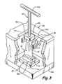
- FIG. 3 is a detail broken view of induction heating chamber 34 positioned for repairing blade 10.
- heating chamber 34 includes window 34c and induction coils 34d surrounding portions of airfoil 16 of blade 10.
- Root 12 of blade 10 is restrained by fixture 40 arranged inside induction heating chamber 34 and a tool, such as wrench 42 may be configured to engage the tip of blade 10 through window 34c.
- Fixture 40 may include root-adaptor 40a configured to receive varying root geometries, such as the dovetail root 12 of blade 10.
- blade 10 may be restrained at root 12 with a fixture configured to clamp root 12, rather than nesting root 12 in an adaptor.
- Wrench 42 may include tip-adaptor 42a and handle 42b.
- Tip-adaptor 42a may be configured to engage the tip of a turbine blade, such as engaging shroud 18 of blade 10 as shown in FIG. 3 .
- tip-adaptor 42a may include a pocket configured to receive the geometry of shroud 18 of blade 10.
- the handle 42b is configured to allow operators to apply an angular load to the tip of blade 10 through adaptor 42a.
- the handle 42b may, instead of the "T" shape shown in FIG. 3 , be connected to and extend laterally from one side of adaptor 42a.
- Induction coils 34d are mounted to induction heating chamber 34 and arranged around portions of blade 10.
- the induction coils 34d may be, for example, arranged around portions of blade 10 subject to the highest stress during blade twist repair operations.
- Induction coils 34d are connected to power source 36 configured to produce an alternating electrical current in coils 34d.
- FIG. 4 is a flow chart illustrating method 50 of repairing a twist angle of a turbine blade, which method 50 includes measuring an existing twist angle of the blade (step 52), restraining a root of the blade (step 54), induction heating one or more portions of the blade (step 56), applying an angular load to a tip of the blade (step 58), and measuring a repaired twist angle of the blade (step 60).
- Gas turbine components may only be repaired or overhauled a certain number of times before it becomes necessary to completely replace the component. In the case of turbine blades, certain dimensional requirements may dictate repair versus replacement of the component. Method 50 may therefore be preceded by checking one or more dimensions of the blade prior to proceeding with any repair procedures. In the case the blade dimensions are not within acceptable tolerance limits, the component may need to be scrapped completely.
- Method 50 includes measuring an existing twist angle of the blade (step 52). Measuring an existing twist angle of the blade (step 52) may include engaging one or more portions of the blade with a twist angle gauge.
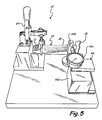
- FIG. 5 is a perspective view of twist angle measuring apparatus 62, which includes toggle clamp 64 and gauge 66. Gauge 66 includes base 66a, probe 66b, and indicator 66c. In FIG. 5 , blade 10 is arranged horizontally and clamped at root 12 by toggle clamp 64. Gauge 66 is positioned adjacent to and configured to engage airfoil 16 of blade 10. Base 66a of gauge 66 may be moved into and out of engagement with airfoil 16 of blade 10. Probe 66b may be spring loaded and connected to indicator 66c.
- the tip of probe 66b may also be contoured to properly engage the contoured geometry of airfoil 16. As base 66a of gauge 66 is moved into position, probe 66b engages airfoil 16 of blade 10 and indicator 66c provides twist angle 22 of blade 10.
- method 50 includes restraining a root of the blade (step 54). Restraining a root of the blade (step 54) may include nesting the root of the blade in a fixture configured to receive the blade root, or, alternatively, clamping the root of the blade in a fixture.
- FIGS. 2 and 3 show system 30 for repairing the twist angle of blade 10 shown in FIGS. 1A and 1B .
- blade 10 is restrained at the root using fixture 42.
- Fixture 42 includes root-adapter 42a configured to receive root 12 of blade 10. Root-adapter 42a may be configured to receive varying root geometries, such as dovetail root 12 of blade 10.
- the root of the blade may be restrained (step 54) using, for example, a vise or toggle clamp to clamp root 12 of blade 10.
- Method 50 also includes induction heating one or more portions of the blade (step 56).
- Induction heating one or more portions of the blade (step 56) may include arranging one or more induction coils about one or more portions of the blade and producing an alternating electrical current in the one or more induction coils.
- induction coils 34d may be arranged around portions of blade 10 inside induction heating chamber 34.
- Induction coils 34d are connected to power source 36 configured to produce an alternating electrical current in coils 34d. The alternating current passing through coils 34d creates an alternating magnetic field.
- Induction coils 34d may be, for example, arranged around portions of blade 10 subject to the highest stress during blade twist repair operations. Induction heating the blade (step 56) may act to substantially reduce the risk of micro-cracking when blade 10 is plastically deformed to restore twist angle 22.
- method 50 includes applying an angular load to a tip of the blade (step 58). Applying an angular load to the tip of the blade (step 58) may be accomplished using a tool.
- a tool In FIG. 3 , for example, an operator may engage shroud 18 of blade 10 with tip-adaptor 42a of wrench 42 and arbitrarily twist blade 10 using wrench 42 one or more times. The operator may apply the angular load(s) to the tip of the blade (step 58) using wrench 42 through window 34c, while blade 10 is arranged inside induction heating chamber 34. Therefore, in some embodiments of the present invention, the angular load may be applied to the tip of the blade (step 58) during induction heating of the blade (step 56).
- applying an angular load to the tip of the blade may include applying a specific, i.e. a first, angular load to the tip of the blade over a period of time.
- the first angular load may be applied to the tip of the blade over a period of time using a motorized twisting apparatus.
- FIG. 6 shows motorized twisting apparatus 70, which includes base 72, fixture 74, and motor 76.
- Fixture 74 and motor 76 are adjustably mounted to base 72 for moving into and out of engagement with blade 10.
- Fixture 74 includes root-adaptor 74a for receiving, for example, root 12 of blade 10.
- Motor 76 includes tip-adaptor 76a for receiving, for example, shroud 18 of blade 10.
- the motor 76 may be electronically controlled to apply the first angular load to shroud 18 of blade 10 over a period of time.
- the motor 76 may be a servo motor capable of producing the first angular load.
- the angular position of the servo motor armature, and therefore the angle through which blade 10 is twisted, and the duration over which the servo motor applies the first angular load may be prescribed by a control circuit integrated with the servo motor.
- Embodiments of the present invention have several advantages over prior blade repair methods and apparatuses. Repairing the twist angle of coated turbine blades with methods and apparatuses according to the present invention without necessitating coating removal increases the number of times the blade may be repaired and returned to service, which in turn increases the longevity and decreases the cost of the engine. Additionally, induction heating the blades prior to applying loads to restore the twist angle of the blade substantially reduces the risk of micro-cracking in the coating or other parts of the blade, thereby increasing the reliability and reducing the risk of failure of the blade after being returned to service.
Landscapes
- Engineering & Computer Science (AREA)
- Mechanical Engineering (AREA)
- General Engineering & Computer Science (AREA)
- Structures Of Non-Positive Displacement Pumps (AREA)
- Turbine Rotor Nozzle Sealing (AREA)
Applications Claiming Priority (1)
| Application Number | Priority Date | Filing Date | Title |
|---|---|---|---|
| SG200802172-7A SG155788A1 (en) | 2008-03-18 | 2008-03-18 | Methods and apparatuses for correcting twist angle in a gas turbine engine blade |
Publications (1)
| Publication Number | Publication Date |
|---|---|
| EP2103779A1 true EP2103779A1 (de) | 2009-09-23 |
Family
ID=40810145
Family Applications (1)
| Application Number | Title | Priority Date | Filing Date |
|---|---|---|---|
| EP09250371A Withdrawn EP2103779A1 (de) | 2008-03-18 | 2009-02-13 | Verfahren und Vorrichtungen zur Korrektur des Verdrehwinkels einer Gasturbinenschaufel |
Country Status (3)
| Country | Link |
|---|---|
| US (1) | US20090313822A1 (de) |
| EP (1) | EP2103779A1 (de) |
| SG (1) | SG155788A1 (de) |
Cited By (3)
| Publication number | Priority date | Publication date | Assignee | Title |
|---|---|---|---|---|
| WO2016139089A1 (de) * | 2015-03-05 | 2016-09-09 | Siemens Aktiengesellschaft | Verfahren zur wiederaufbereitung eines bauteils mittels lokaler thermomechanischer behandlung |
| EP3205451A1 (de) * | 2016-02-12 | 2017-08-16 | Siemens Aktiengesellschaft | Turbinenschaufeltorsionsklemme |
| FR3081733A1 (fr) * | 2018-06-05 | 2019-12-06 | Safran Aircraft Engines | Outillage de vrillage d'une aube de turbomachine |
Families Citing this family (9)
| Publication number | Priority date | Publication date | Assignee | Title |
|---|---|---|---|---|
| US7970555B2 (en) * | 2008-04-15 | 2011-06-28 | United Technologies Corporation | Method for developing a repair process to correct a deformed gas turbine engine component |
| US8887390B2 (en) | 2008-08-15 | 2014-11-18 | Dresser-Rand Company | Method for correcting downstream deflection in gas turbine nozzles |
| DE102009052881A1 (de) * | 2009-11-13 | 2011-05-26 | Mtu Aero Engines Gmbh | Gasturbinenschaufel für eine Strömungsmaschine |
| US9018560B2 (en) * | 2011-02-28 | 2015-04-28 | General Electric Company | Repair alignment method and apparatus for turbine components |
| US9260978B2 (en) | 2012-03-19 | 2016-02-16 | General Electric Company | System and method for heating a stator segment |
| WO2014006467A2 (en) * | 2012-06-13 | 2014-01-09 | Pratt & Whitney Services Pte Ltd | Tip fabrication for rotor blade or stator vane airfoil |
| US9138793B2 (en) * | 2013-03-14 | 2015-09-22 | Chromalloy Gas Turbine Llc | Process and apparatus to restore distorted features on gas turbine vanes |
| US9797253B2 (en) | 2014-09-17 | 2017-10-24 | General Electric Company | System and method for repairing blades |
| US10125611B2 (en) * | 2016-02-17 | 2018-11-13 | General Electric Company | System and method for in situ repair of turbine blades of gas turbine engines |
Citations (4)
| Publication number | Priority date | Publication date | Assignee | Title |
|---|---|---|---|---|
| JPS58205639A (ja) * | 1982-05-26 | 1983-11-30 | Hitachi Ltd | ブレ−ドの成形方法 |
| DE19630703A1 (de) * | 1996-07-30 | 1998-02-05 | Mtu Muenchen Gmbh | Verfahren und Vorrichtung zum Reparaturschweißen von Teilen aus Ni-Basis-Legierungen |
| EP1310632A1 (de) * | 2001-11-09 | 2003-05-14 | GE Aviation Services Operation (Pte) Ltd. | Verfahren und Vorrichtung zur Korrektur der Verwindung einer Schaufel |
| EP1857217A1 (de) * | 2006-05-17 | 2007-11-21 | General Electric Company | Vorrichtung zur Wiederherstellung von Hochdruckturbinenschaufel und Verfahren zur Wärmebehandlung |
Family Cites Families (22)
| Publication number | Priority date | Publication date | Assignee | Title |
|---|---|---|---|---|
| US3653128A (en) * | 1970-04-03 | 1972-04-04 | Chromalloy American Corp | Means for measuring twist in a turbine vane |
| US4146967A (en) * | 1977-08-15 | 1979-04-03 | The Boeing Company | Rotor blade inspection fixture |
| EP0056328B1 (de) * | 1981-01-12 | 1986-12-10 | Refurbished Turbine Components Limited | Wiederherstellung einer Schaufel |
| US4639991A (en) * | 1981-11-16 | 1987-02-03 | United Technologies Corporation | Process for producing a new edge on an airfoil blade particularly the fan blade for a gas turbine engine |
| US4454656A (en) * | 1982-09-22 | 1984-06-19 | United Technologies Corporation | Minimum chord gauge |
| US4908782A (en) * | 1983-05-19 | 1990-03-13 | Compressor Components Textron Inc. | Airfoil inspection method |
| US4856943A (en) * | 1988-04-29 | 1989-08-15 | United Technologies Corporation | Airfoil incidence angle adjustment method |
| US5063662A (en) * | 1990-03-22 | 1991-11-12 | United Technologies Corporation | Method of forming a hollow blade |
| US5162659A (en) * | 1991-03-06 | 1992-11-10 | Northwest Airlines, Inc. | Method and apparatus for noncontact inspection of engine blades |
| DE4141927C2 (de) * | 1991-12-19 | 1995-06-14 | Mtu Maintenance Gmbh | Verfahren und Vorrichtung zum Schweißen von Werkstücken |
| US5625958A (en) * | 1995-09-06 | 1997-05-06 | United Technologies Corporation | Method and a gauge for measuring the service life remaining in a blade |
| US5771726A (en) * | 1996-08-28 | 1998-06-30 | Kenney Manufacturing Company | Apparatus and method for twisting hollow rods |
| DE19831736C2 (de) * | 1998-07-15 | 2000-05-31 | Mtu Muenchen Gmbh | Verfahren zur Reparatur und Herstellung eines integral beschaufelten Rotors für eine Strömungsmaschine |
| US6209216B1 (en) * | 1999-08-16 | 2001-04-03 | General Electric Company | Methods and apparatus for measuring airfoil coordinates |
| DE10102991C2 (de) * | 2000-02-19 | 2003-11-20 | Ald Vacuum Techn Ag | Einrichtung zum Aufheizen eines Werkstücks aus Metall |
| DE10062310C2 (de) * | 2000-12-14 | 2002-11-07 | Geesthacht Gkss Forschung | Verfahren zur Behandlung metallischer Werkstoffe |
| JP4028442B2 (ja) * | 2002-06-26 | 2007-12-26 | 株式会社東芝 | ガスタービン翼の変形修正装置及び方法 |
| US6959572B2 (en) * | 2002-12-20 | 2005-11-01 | Proenterpriz, Inc. | Fixture for holding metals parts for bending or twist correction |
| US7034262B2 (en) * | 2004-03-23 | 2006-04-25 | General Electric Company | Apparatus and methods for repairing tenons on turbine buckets |
| US7536783B2 (en) * | 2005-10-13 | 2009-05-26 | Siemens Energy, Inc. | Turbine vane airfoil reconfiguration method |
| US8122601B2 (en) * | 2008-04-15 | 2012-02-28 | United Technologies Corporation | Methods for correcting twist angle in a gas turbine engine blade |
| US8127581B2 (en) * | 2008-04-15 | 2012-03-06 | United Technologies Corporation | Turbine blade twist angle correction tooling |
-
2008
- 2008-03-18 SG SG200802172-7A patent/SG155788A1/en unknown
- 2008-06-05 US US12/133,490 patent/US20090313822A1/en not_active Abandoned
-
2009
- 2009-02-13 EP EP09250371A patent/EP2103779A1/de not_active Withdrawn
Patent Citations (4)
| Publication number | Priority date | Publication date | Assignee | Title |
|---|---|---|---|---|
| JPS58205639A (ja) * | 1982-05-26 | 1983-11-30 | Hitachi Ltd | ブレ−ドの成形方法 |
| DE19630703A1 (de) * | 1996-07-30 | 1998-02-05 | Mtu Muenchen Gmbh | Verfahren und Vorrichtung zum Reparaturschweißen von Teilen aus Ni-Basis-Legierungen |
| EP1310632A1 (de) * | 2001-11-09 | 2003-05-14 | GE Aviation Services Operation (Pte) Ltd. | Verfahren und Vorrichtung zur Korrektur der Verwindung einer Schaufel |
| EP1857217A1 (de) * | 2006-05-17 | 2007-11-21 | General Electric Company | Vorrichtung zur Wiederherstellung von Hochdruckturbinenschaufel und Verfahren zur Wärmebehandlung |
Cited By (3)
| Publication number | Priority date | Publication date | Assignee | Title |
|---|---|---|---|---|
| WO2016139089A1 (de) * | 2015-03-05 | 2016-09-09 | Siemens Aktiengesellschaft | Verfahren zur wiederaufbereitung eines bauteils mittels lokaler thermomechanischer behandlung |
| EP3205451A1 (de) * | 2016-02-12 | 2017-08-16 | Siemens Aktiengesellschaft | Turbinenschaufeltorsionsklemme |
| FR3081733A1 (fr) * | 2018-06-05 | 2019-12-06 | Safran Aircraft Engines | Outillage de vrillage d'une aube de turbomachine |
Also Published As
| Publication number | Publication date |
|---|---|
| US20090313822A1 (en) | 2009-12-24 |
| SG155788A1 (en) | 2009-10-29 |
Similar Documents
| Publication | Publication Date | Title |
|---|---|---|
| US20090313822A1 (en) | Methods and apparatuses for correcting twist angle in a gas turbine engine blade | |
| US8127581B2 (en) | Turbine blade twist angle correction tooling | |
| US20180216464A1 (en) | Method of repairing a blisk | |
| US8047771B2 (en) | Turbine nozzles and methods of manufacturing the same | |
| EP3115147A1 (de) | Systeme und verfahren zur reparatur von turbinenschaufeln | |
| EP2361999A1 (de) | Reparatur einer Beschichtung auf einem Turbinenbauteil | |
| US9694440B2 (en) | Support collar geometry for linear friction welding | |
| EP3839081B1 (de) | System zum anwenden mehrerer thermischer behandlungen an werkstücken und zugehörige turbomaschinenkomponenten | |
| US20250257659A1 (en) | Airfoil joining apparatus and methods | |
| US8122601B2 (en) | Methods for correcting twist angle in a gas turbine engine blade | |
| US20090255115A1 (en) | Method for developing a repair process to correct a deformed gas turbine engine component | |
| US9566669B2 (en) | Tip fabrication for rotor blade or stator vane airfoil | |
| EP2969281B1 (de) | Verfahren und vorrichtung zur wiederherstellung verzerrter merkmale auf gasturbinenleitschaufeln | |
| KR102295676B1 (ko) | 터보머신 엔진 구성요소의 브레이즈 수리 | |
| US10239151B2 (en) | Linear friction welding method | |
| EP3835551B1 (de) | Turbomaschinenschaufel und verfahren zur wärmebehandlung einer solchen turbomaschinenschaufel durch anwendung mehrerer thermischer behandlungen | |
| EP3135427B1 (de) | Verfahren, vorrichtung und computerprogramm zur reparatur von tragflügeln von gasturbinenmotoren | |
| Barhanko et al. | Development of Blade Tip Repair for SGT-700 Turbine Blade Stage 1, With Oxidation Resistant Weld Alloy | |
| Schwienbacher et al. | Repair of Aircraft Combustors with Industrial Robots | |
| CN117813441A (zh) | 具有轴向偏移刀齿的涡轮叶片尖端护罩和相关表面轮廓以及方法 |
Legal Events
| Date | Code | Title | Description |
|---|---|---|---|
| PUAI | Public reference made under article 153(3) epc to a published international application that has entered the european phase |
Free format text: ORIGINAL CODE: 0009012 |
|
| AK | Designated contracting states |
Kind code of ref document: A1 Designated state(s): AT BE BG CH CY CZ DE DK EE ES FI FR GB GR HR HU IE IS IT LI LT LU LV MC MK MT NL NO PL PT RO SE SI SK TR |
|
| AX | Request for extension of the european patent |
Extension state: AL BA RS |
|
| 17P | Request for examination filed |
Effective date: 20091222 |
|
| 17Q | First examination report despatched |
Effective date: 20100208 |
|
| AKX | Designation fees paid |
Designated state(s): DE GB |
|
| STAA | Information on the status of an ep patent application or granted ep patent |
Free format text: STATUS: THE APPLICATION IS DEEMED TO BE WITHDRAWN |
|
| 18D | Application deemed to be withdrawn |
Effective date: 20100619 |