EP2103783A2 - Stator de compresseur doté d'une bande de toit partielle - Google Patents
Stator de compresseur doté d'une bande de toit partielle Download PDFInfo
- Publication number
- EP2103783A2 EP2103783A2 EP09003391A EP09003391A EP2103783A2 EP 2103783 A2 EP2103783 A2 EP 2103783A2 EP 09003391 A EP09003391 A EP 09003391A EP 09003391 A EP09003391 A EP 09003391A EP 2103783 A2 EP2103783 A2 EP 2103783A2
- Authority
- EP
- European Patent Office
- Prior art keywords
- stator
- rotor
- shroud
- hub
- gasturbinenaxialverdichter
- Prior art date
- Legal status (The legal status is an assumption and is not a legal conclusion. Google has not performed a legal analysis and makes no representation as to the accuracy of the status listed.)
- Withdrawn
Links
Images


Classifications
-
- F—MECHANICAL ENGINEERING; LIGHTING; HEATING; WEAPONS; BLASTING
- F01—MACHINES OR ENGINES IN GENERAL; ENGINE PLANTS IN GENERAL; STEAM ENGINES
- F01D—NON-POSITIVE DISPLACEMENT MACHINES OR ENGINES, e.g. STEAM TURBINES
- F01D9/00—Stators
- F01D9/02—Nozzles; Nozzle boxes; Stator blades; Guide conduits, e.g. individual nozzles
- F01D9/04—Nozzles; Nozzle boxes; Stator blades; Guide conduits, e.g. individual nozzles forming ring or sector
- F01D9/041—Nozzles; Nozzle boxes; Stator blades; Guide conduits, e.g. individual nozzles forming ring or sector using blades
-
- F—MECHANICAL ENGINEERING; LIGHTING; HEATING; WEAPONS; BLASTING
- F01—MACHINES OR ENGINES IN GENERAL; ENGINE PLANTS IN GENERAL; STEAM ENGINES
- F01D—NON-POSITIVE DISPLACEMENT MACHINES OR ENGINES, e.g. STEAM TURBINES
- F01D11/00—Preventing or minimising internal leakage of working-fluid, e.g. between stages
- F01D11/001—Preventing or minimising internal leakage of working-fluid, e.g. between stages for sealing space between stator blade and rotor
-
- F—MECHANICAL ENGINEERING; LIGHTING; HEATING; WEAPONS; BLASTING
- F01—MACHINES OR ENGINES IN GENERAL; ENGINE PLANTS IN GENERAL; STEAM ENGINES
- F01D—NON-POSITIVE DISPLACEMENT MACHINES OR ENGINES, e.g. STEAM TURBINES
- F01D17/00—Regulating or controlling by varying flow
- F01D17/10—Final actuators
- F01D17/12—Final actuators arranged in stator parts
- F01D17/14—Final actuators arranged in stator parts varying effective cross-sectional area of nozzles or guide conduits
- F01D17/16—Final actuators arranged in stator parts varying effective cross-sectional area of nozzles or guide conduits by means of nozzle vanes
- F01D17/162—Final actuators arranged in stator parts varying effective cross-sectional area of nozzles or guide conduits by means of nozzle vanes for axial flow, i.e. the vanes turning around axes which are essentially perpendicular to the rotor centre line
-
- F—MECHANICAL ENGINEERING; LIGHTING; HEATING; WEAPONS; BLASTING
- F04—POSITIVE - DISPLACEMENT MACHINES FOR LIQUIDS; PUMPS FOR LIQUIDS OR ELASTIC FLUIDS
- F04D—NON-POSITIVE-DISPLACEMENT PUMPS
- F04D29/00—Details, component parts, or accessories
- F04D29/08—Sealings
- F04D29/16—Sealings between pressure and suction sides
- F04D29/161—Sealings between pressure and suction sides especially adapted for elastic fluid pumps
- F04D29/164—Sealings between pressure and suction sides especially adapted for elastic fluid pumps of an axial flow wheel
-
- F—MECHANICAL ENGINEERING; LIGHTING; HEATING; WEAPONS; BLASTING
- F04—POSITIVE - DISPLACEMENT MACHINES FOR LIQUIDS; PUMPS FOR LIQUIDS OR ELASTIC FLUIDS
- F04D—NON-POSITIVE-DISPLACEMENT PUMPS
- F04D29/00—Details, component parts, or accessories
- F04D29/40—Casings; Connections of working fluid
- F04D29/52—Casings; Connections of working fluid for axial pumps
- F04D29/54—Fluid-guiding means, e.g. diffusers
- F04D29/541—Specially adapted for elastic fluid pumps
- F04D29/542—Bladed diffusers
-
- F—MECHANICAL ENGINEERING; LIGHTING; HEATING; WEAPONS; BLASTING
- F05—INDEXING SCHEMES RELATING TO ENGINES OR PUMPS IN VARIOUS SUBCLASSES OF CLASSES F01-F04
- F05D—INDEXING SCHEME FOR ASPECTS RELATING TO NON-POSITIVE-DISPLACEMENT MACHINES OR ENGINES, GAS-TURBINES OR JET-PROPULSION PLANTS
- F05D2240/00—Components
- F05D2240/10—Stators
- F05D2240/11—Shroud seal segments
-
- F—MECHANICAL ENGINEERING; LIGHTING; HEATING; WEAPONS; BLASTING
- F05—INDEXING SCHEMES RELATING TO ENGINES OR PUMPS IN VARIOUS SUBCLASSES OF CLASSES F01-F04
- F05D—INDEXING SCHEME FOR ASPECTS RELATING TO NON-POSITIVE-DISPLACEMENT MACHINES OR ENGINES, GAS-TURBINES OR JET-PROPULSION PLANTS
- F05D2240/00—Components
- F05D2240/10—Stators
- F05D2240/12—Fluid guiding means, e.g. vanes
Definitions
- the invention relates to a Gasturbinenaxialver disguiser according to the features of the preamble of claim 1.
- the invention relates to an axial compressor of a gas turbine with a housing and a hub, which form an annular channel, in which at least one stator and a rotor are arranged.
- the stator comprises a row of stator blades
- the rotor as usual, each comprises a row of rotor blades.
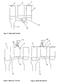
- Axial compressors consist of one or more compressor stages, which consist of a rotor 4 and a stator 2, moreover, before the first stage, the compressor may also have a so-called leading wheel 1 ( Fig. 1 ).
- This shroud 11 extends over the entire axial length of the stator 2 from the leading edge to the trailing edge and even beyond both edges.
- the shroud 11 itself hangs freely over the underlying rotor shaft 6. This arrangement causes between the rotor 4 and stator 5, an axial gap in front of and behind the stator 2 is formed. This gap leads to flow leakage, which is reduced by seals 12 with respect to the rotor shaft 6 ( Fig. 3 ).
- the stators are 2 with rotating spindles 14 in the housing ( Fig. 4 ) or suspended in the housing and in the Nabendeckband ( Fig. 5 ).
- the spindles 14 are connected to plates with the blade. They can either be arranged at the stator front edge - then only behind the spindle 14, a radial gap between the blade end and the housing wall or the Nabendeckband - or they can be arranged so that both before and behind the spindle 14, a radial gap is formed ,
- the invention has for its object to provide a Gasurbinenaxialverêtr of the type mentioned above, which has a simple design and cost manufacturability increased efficiency and avoids the disadvantages of the prior art.
- the stator comprises a shroud at the respective free end of the stator blades.
- this shroud does not extend over the entire axial length of the stator blades, but only over a subarea. It is inventively possible, the shroud in a central region of the stator blades, centrally to this or in the flow direction at the inflow of the stator or at the outflow area to provide.
- the stator according to the invention thus has over a portion of its axial length on a shroud, which is preferably sealed by means of a conventional seal (lip seal or the like) to prevent leakage currents or reduce.
- a conventional seal lip seal or the like
- the invention provides that a further axial portion of the stator is formed adjacent to a rotor hub or rotor platform. This creates a radial hub gap between the rotor hub and the stator blade.
- the rotor hub or rotor platform can preferably be designed in the form of an extension or an attachment of a rotor disk.
- the axial length of the shroud and the axial length of the rotor platform or hub may add up to the total axial length of the stator or stator blade. However, it is also possible to seal and form only subsets of the entire length in the manner described.
- the axial portion of the stator provided with a hub gap may be arranged on one side in the flow direction in front of or behind the area provided with the shroud.
- various modifications and variations are possible according to the invention.
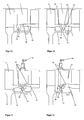
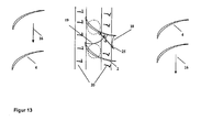
- the invention thus provides that the rotor platform 23 of the downstream and / or the upstream rotor 4 is extended below the stator 2, so that below the stator. 2 a rotating hub body is located.
- the rotating hub body (rotor platform 23) under the stator blade is not as in the stator 2 with full gap continuously to the next rotor 4, but only covers part of the stator 2.
- the stator 2 has a shroud 11.
- the hub gap 10 is located either before and behind or just behind the sub-deck 21, which hangs between the two rotating Rotornabenanalysisn (rotor platform 23).
- the axial gap between the rotating hub body and the sub-cover tape 21 is located under the stator blade.
- adjustable stators ( Fig. 9-12 ) is in the sub-deck 21 of the base, ie accommodated the recording of the spindle axis, as is the case with a full-coverage tape.
Landscapes
- Engineering & Computer Science (AREA)
- Mechanical Engineering (AREA)
- General Engineering & Computer Science (AREA)
- Structures Of Non-Positive Displacement Pumps (AREA)
- Crushing And Pulverization Processes (AREA)
Applications Claiming Priority (1)
| Application Number | Priority Date | Filing Date | Title |
|---|---|---|---|
| DE102008014743A DE102008014743A1 (de) | 2008-03-18 | 2008-03-18 | Verdichterstator mit Teildeckband |
Publications (2)
| Publication Number | Publication Date |
|---|---|
| EP2103783A2 true EP2103783A2 (fr) | 2009-09-23 |
| EP2103783A3 EP2103783A3 (fr) | 2014-05-14 |
Family
ID=40848771
Family Applications (1)
| Application Number | Title | Priority Date | Filing Date |
|---|---|---|---|
| EP09003391.1A Withdrawn EP2103783A3 (fr) | 2008-03-18 | 2009-03-09 | Stator de compresseur doté d'une bande de toit partielle |
Country Status (3)
| Country | Link |
|---|---|
| US (1) | US8235654B2 (fr) |
| EP (1) | EP2103783A3 (fr) |
| DE (1) | DE102008014743A1 (fr) |
Cited By (2)
| Publication number | Priority date | Publication date | Assignee | Title |
|---|---|---|---|---|
| WO2011124214A3 (fr) * | 2010-04-10 | 2011-12-01 | Mtu Aero Engines Gmbh | Aube directrice d'une machine d'écoulement |
| WO2020201642A1 (fr) * | 2019-04-03 | 2020-10-08 | Safran Aircraft Engines | Aube de stator a calage variable pour une turbomachine d'aeronef |
Families Citing this family (8)
| Publication number | Priority date | Publication date | Assignee | Title |
|---|---|---|---|---|
| US8905711B2 (en) * | 2011-05-26 | 2014-12-09 | United Technologies Corporation | Ceramic matrix composite vane structures for a gas turbine engine turbine |
| US9062560B2 (en) * | 2012-03-13 | 2015-06-23 | United Technologies Corporation | Gas turbine engine variable stator vane assembly |
| US20130315716A1 (en) * | 2012-05-22 | 2013-11-28 | General Electric Company | Turbomachine having clearance control capability and system therefor |
| EP2961941B1 (fr) | 2013-02-26 | 2020-02-19 | Rolls-Royce Corporation | Appareils comprenant une aube statorique de turbine pivotable |
| DE102014203605A1 (de) | 2014-02-27 | 2015-08-27 | Rolls-Royce Deutschland Ltd & Co Kg | Schaufelreihengruppe |
| US20180156236A1 (en) * | 2016-12-02 | 2018-06-07 | Pratt & Whitney Canada Corp. | Gas turbine engine bleed configuration |
| KR102351758B1 (ko) * | 2017-03-30 | 2022-01-14 | 미츠비시 파워 가부시키가이샤 | 가변 정익 및 압축기 |
| FR3109959B1 (fr) * | 2020-05-06 | 2022-04-22 | Safran Helicopter Engines | Compresseur de turbomachine comportant une paroi fixe pourvue d’un traitement de forme |
Family Cites Families (14)
| Publication number | Priority date | Publication date | Assignee | Title |
|---|---|---|---|---|
| BE492385A (fr) * | 1948-11-27 | |||
| BE496713A (fr) * | 1949-07-01 | |||
| US2868439A (en) * | 1954-05-07 | 1959-01-13 | Goodyear Aircraft Corp | Plastic axial-flow compressor for gas turbines |
| US3146938A (en) * | 1962-12-28 | 1964-09-01 | Gen Electric | Shrouding for compressor stator vanes |
| US4477089A (en) * | 1982-07-26 | 1984-10-16 | Avco Corporation | Honeycomb seal for turbine engines |
| US4619580A (en) * | 1983-09-08 | 1986-10-28 | The Boeing Company | Variable camber vane and method therefor |
| US4869640A (en) * | 1988-09-16 | 1989-09-26 | United Technologies Corporation | Controlled temperature rotating seal |
| US5157914A (en) * | 1990-12-27 | 1992-10-27 | United Technologies Corporation | Modulated gas turbine cooling air |
| US5639212A (en) * | 1996-03-29 | 1997-06-17 | General Electric Company | Cavity sealed compressor |
| US5752802A (en) * | 1996-12-19 | 1998-05-19 | Solar Turbines Incorporated | Sealing apparatus for airfoils of gas turbine engines |
| US20060029494A1 (en) * | 2003-05-27 | 2006-02-09 | General Electric Company | High temperature ceramic lubricant |
| US7407369B2 (en) * | 2004-12-29 | 2008-08-05 | United Technologies Corporation | Gas turbine engine blade tip clearance apparatus and method |
| US7334983B2 (en) | 2005-10-27 | 2008-02-26 | United Technologies Corporation | Integrated bladed fluid seal |
| JP5228311B2 (ja) * | 2006-11-08 | 2013-07-03 | 株式会社Ihi | 圧縮機静翼 |
-
2008
- 2008-03-18 DE DE102008014743A patent/DE102008014743A1/de not_active Withdrawn
-
2009
- 2009-03-09 EP EP09003391.1A patent/EP2103783A3/fr not_active Withdrawn
- 2009-03-18 US US12/382,573 patent/US8235654B2/en not_active Expired - Fee Related
Cited By (7)
| Publication number | Priority date | Publication date | Assignee | Title |
|---|---|---|---|---|
| WO2011124214A3 (fr) * | 2010-04-10 | 2011-12-01 | Mtu Aero Engines Gmbh | Aube directrice d'une machine d'écoulement |
| US8613592B2 (en) | 2010-04-10 | 2013-12-24 | Mtu Aero Engines Gmbh | Guide blade of a turbomachine |
| WO2020201642A1 (fr) * | 2019-04-03 | 2020-10-08 | Safran Aircraft Engines | Aube de stator a calage variable pour une turbomachine d'aeronef |
| FR3094746A1 (fr) * | 2019-04-03 | 2020-10-09 | Safran Aircraft Engines | Aube de stator a calage variable pour une turbomachine d’aeronef |
| GB2596677A (en) * | 2019-04-03 | 2022-01-05 | Safran Aircraft Engines | Variable-pitch stator blade for an aircraft turbine engine |
| GB2596677B (en) * | 2019-04-03 | 2023-01-18 | Safran Aircraft Engines | Variable-pitch stator blade for an aircraft turbine engine |
| US11891901B2 (en) | 2019-04-03 | 2024-02-06 | Safran Aircraft Engines | Variable-pitch stator vane for an aircraft turbine engine |
Also Published As
| Publication number | Publication date |
|---|---|
| US20090238682A1 (en) | 2009-09-24 |
| US8235654B2 (en) | 2012-08-07 |
| EP2103783A3 (fr) | 2014-05-14 |
| DE102008014743A1 (de) | 2009-09-24 |
Similar Documents
| Publication | Publication Date | Title |
|---|---|---|
| EP2103783A2 (fr) | Stator de compresseur doté d'une bande de toit partielle | |
| EP1659293B1 (fr) | Turbomachine | |
| EP0598174B1 (fr) | Turbosoufflante pour une machine à combustion interne | |
| DE2718693C3 (de) | Bypaßanordnung zur Geräuschverminderung einer Gebläsestufe eines Gasturbinenstrahltriebwerkes | |
| EP2993357B1 (fr) | Étage de compresseur radial | |
| EP2921716B1 (fr) | Groupe de série d'aubes | |
| EP2294286B1 (fr) | Rotor avex aubes mobiles carenées d'une turbomachine | |
| EP0118769B1 (fr) | Turbine à plusieurs étages avec bandages extérieurs | |
| EP2138727A2 (fr) | Bande de recouvrement d'aube dotée d'un passage | |
| EP2993356A1 (fr) | Étage de compresseur radial | |
| EP2626513B1 (fr) | Ensemble d'aubes en tandem | |
| EP1998049A2 (fr) | Aube de machine de travail d'écoulement doté d'une conception à plusieurs profiles | |
| EP1637697B1 (fr) | Passage d'une machine à écoulement avec intervalle axial ayant une concentration inférieure à 1 | |
| EP3431708A1 (fr) | Dispositif d'écoulement autour, turbomachine et application associées | |
| EP2522833B1 (fr) | Turbine à gaz avec dispositif de prélèvement d'air de tirage | |
| DE102018206601A1 (de) | Schaufel, Schaufelsegment und Baugruppe für eine Turbomaschine und Turbomaschine | |
| DE443163C (de) | Schaufelung fuer Turbomaschinen u. dgl. | |
| EP2650520B1 (fr) | Turbine à gaz d'aéronef avec canal de décharge dans un pied d'aube de guidage d'un canal de flux secondaire | |
| DE10352789B4 (de) | Gasturbine | |
| EP2787180A1 (fr) | Agencement d'aubes directrices pour une turbomachine | |
| DE1050123B (de) | Brennkraftturbinenanlage mit Axialdruckverdichter | |
| EP2177770A2 (fr) | Compresseur pour une turbine à gaz | |
| EP2298643B1 (fr) | Rotor d'entraînement doté d'un canal d'aération | |
| WO2007045547A1 (fr) | Plaquettes d'etancheite pour la reduction d'un courant de fuite | |
| DE8605507U1 (de) | Einrichtung zur Belüftung von Rotorbauteilen für Verdichter von Gasturbinentriebwerken |
Legal Events
| Date | Code | Title | Description |
|---|---|---|---|
| PUAI | Public reference made under article 153(3) epc to a published international application that has entered the european phase |
Free format text: ORIGINAL CODE: 0009012 |
|
| AK | Designated contracting states |
Kind code of ref document: A2 Designated state(s): AT BE BG CH CY CZ DE DK EE ES FI FR GB GR HR HU IE IS IT LI LT LU LV MC MK MT NL NO PL PT RO SE SI SK TR |
|
| AX | Request for extension of the european patent |
Extension state: AL BA RS |
|
| PUAL | Search report despatched |
Free format text: ORIGINAL CODE: 0009013 |
|
| AK | Designated contracting states |
Kind code of ref document: A3 Designated state(s): AT BE BG CH CY CZ DE DK EE ES FI FR GB GR HR HU IE IS IT LI LT LU LV MC MK MT NL NO PL PT RO SE SI SK TR |
|
| AX | Request for extension of the european patent |
Extension state: AL BA RS |
|
| RIC1 | Information provided on ipc code assigned before grant |
Ipc: F01D 9/04 20060101AFI20140404BHEP Ipc: F01D 17/16 20060101ALI20140404BHEP Ipc: F01D 11/00 20060101ALI20140404BHEP |
|
| AKY | No designation fees paid | ||
| AXX | Extension fees paid |
Extension state: BA Extension state: RS Extension state: AL |
|
| REG | Reference to a national code |
Ref country code: DE Ref legal event code: R108 |
|
| REG | Reference to a national code |
Ref country code: DE Ref legal event code: R108 Effective date: 20150121 |
|
| STAA | Information on the status of an ep patent application or granted ep patent |
Free format text: STATUS: THE APPLICATION IS DEEMED TO BE WITHDRAWN |
|
| 18D | Application deemed to be withdrawn |
Effective date: 20141115 |