EP2138727A2 - Bande de recouvrement d'aube dotée d'un passage - Google Patents
Bande de recouvrement d'aube dotée d'un passage Download PDFInfo
- Publication number
- EP2138727A2 EP2138727A2 EP20090005839 EP09005839A EP2138727A2 EP 2138727 A2 EP2138727 A2 EP 2138727A2 EP 20090005839 EP20090005839 EP 20090005839 EP 09005839 A EP09005839 A EP 09005839A EP 2138727 A2 EP2138727 A2 EP 2138727A2
- Authority
- EP
- European Patent Office
- Prior art keywords
- shroud
- blade
- flow path
- main flow
- point
- Prior art date
- Legal status (The legal status is an assumption and is not a legal conclusion. Google has not performed a legal analysis and makes no representation as to the accuracy of the status listed.)
- Granted
Links
- 239000012530 fluid Substances 0.000 claims description 57
- 230000033001 locomotion Effects 0.000 claims description 22
- 238000011144 upstream manufacturing Methods 0.000 claims description 20
- 238000007789 sealing Methods 0.000 claims description 13
- 230000000149 penetrating effect Effects 0.000 claims description 8
- 230000000694 effects Effects 0.000 claims description 3
- 239000000565 sealant Substances 0.000 description 4
- 230000002349 favourable effect Effects 0.000 description 2
- 238000000926 separation method Methods 0.000 description 2
- 239000007787 solid Substances 0.000 description 2
- 230000002411 adverse Effects 0.000 description 1
- 230000001419 dependent effect Effects 0.000 description 1
- 230000009931 harmful effect Effects 0.000 description 1
- 239000007788 liquid Substances 0.000 description 1
- 230000003068 static effect Effects 0.000 description 1
- 230000008719 thickening Effects 0.000 description 1
Images



Classifications
-
- F—MECHANICAL ENGINEERING; LIGHTING; HEATING; WEAPONS; BLASTING
- F02—COMBUSTION ENGINES; HOT-GAS OR COMBUSTION-PRODUCT ENGINE PLANTS
- F02C—GAS-TURBINE PLANTS; AIR INTAKES FOR JET-PROPULSION PLANTS; CONTROLLING FUEL SUPPLY IN AIR-BREATHING JET-PROPULSION PLANTS
- F02C6/00—Plural gas-turbine plants; Combinations of gas-turbine plants with other apparatus; Adaptations of gas-turbine plants for special use
- F02C6/04—Gas-turbine plants providing heated or pressurised working fluid for other apparatus, e.g. without mechanical power output
- F02C6/06—Gas-turbine plants providing heated or pressurised working fluid for other apparatus, e.g. without mechanical power output providing compressed gas
- F02C6/08—Gas-turbine plants providing heated or pressurised working fluid for other apparatus, e.g. without mechanical power output providing compressed gas the gas being bled from the gas-turbine compressor
-
- F—MECHANICAL ENGINEERING; LIGHTING; HEATING; WEAPONS; BLASTING
- F01—MACHINES OR ENGINES IN GENERAL; ENGINE PLANTS IN GENERAL; STEAM ENGINES
- F01D—NON-POSITIVE DISPLACEMENT MACHINES OR ENGINES, e.g. STEAM TURBINES
- F01D11/00—Preventing or minimising internal leakage of working-fluid, e.g. between stages
- F01D11/001—Preventing or minimising internal leakage of working-fluid, e.g. between stages for sealing space between stator blade and rotor
-
- F—MECHANICAL ENGINEERING; LIGHTING; HEATING; WEAPONS; BLASTING
- F01—MACHINES OR ENGINES IN GENERAL; ENGINE PLANTS IN GENERAL; STEAM ENGINES
- F01D—NON-POSITIVE DISPLACEMENT MACHINES OR ENGINES, e.g. STEAM TURBINES
- F01D5/00—Blades; Blade-carrying members; Heating, heat-insulating, cooling or antivibration means on the blades or the members
- F01D5/12—Blades
- F01D5/22—Blade-to-blade connections, e.g. for damping vibrations
- F01D5/225—Blade-to-blade connections, e.g. for damping vibrations by shrouding
-
- F—MECHANICAL ENGINEERING; LIGHTING; HEATING; WEAPONS; BLASTING
- F04—POSITIVE - DISPLACEMENT MACHINES FOR LIQUIDS; PUMPS FOR LIQUIDS OR ELASTIC FLUIDS
- F04D—NON-POSITIVE-DISPLACEMENT PUMPS
- F04D27/00—Control, e.g. regulation, of pumps, pumping installations or pumping systems specially adapted for elastic fluids
- F04D27/02—Surge control
- F04D27/0207—Surge control by bleeding, bypassing or recycling fluids
- F04D27/0238—Details or means for fluid reinjection
-
- F—MECHANICAL ENGINEERING; LIGHTING; HEATING; WEAPONS; BLASTING
- F04—POSITIVE - DISPLACEMENT MACHINES FOR LIQUIDS; PUMPS FOR LIQUIDS OR ELASTIC FLUIDS
- F04D—NON-POSITIVE-DISPLACEMENT PUMPS
- F04D29/00—Details, component parts, or accessories
- F04D29/40—Casings; Connections of working fluid
- F04D29/52—Casings; Connections of working fluid for axial pumps
- F04D29/54—Fluid-guiding means, e.g. diffusers
- F04D29/541—Specially adapted for elastic fluid pumps
- F04D29/542—Bladed diffusers
-
- F—MECHANICAL ENGINEERING; LIGHTING; HEATING; WEAPONS; BLASTING
- F04—POSITIVE - DISPLACEMENT MACHINES FOR LIQUIDS; PUMPS FOR LIQUIDS OR ELASTIC FLUIDS
- F04D—NON-POSITIVE-DISPLACEMENT PUMPS
- F04D29/00—Details, component parts, or accessories
- F04D29/66—Combating cavitation, whirls, noise, vibration or the like; Balancing
- F04D29/68—Combating cavitation, whirls, noise, vibration or the like; Balancing by influencing boundary layers
- F04D29/681—Combating cavitation, whirls, noise, vibration or the like; Balancing by influencing boundary layers especially adapted for elastic fluid pumps
- F04D29/684—Combating cavitation, whirls, noise, vibration or the like; Balancing by influencing boundary layers especially adapted for elastic fluid pumps by fluid injection
-
- Y—GENERAL TAGGING OF NEW TECHNOLOGICAL DEVELOPMENTS; GENERAL TAGGING OF CROSS-SECTIONAL TECHNOLOGIES SPANNING OVER SEVERAL SECTIONS OF THE IPC; TECHNICAL SUBJECTS COVERED BY FORMER USPC CROSS-REFERENCE ART COLLECTIONS [XRACs] AND DIGESTS
- Y02—TECHNOLOGIES OR APPLICATIONS FOR MITIGATION OR ADAPTATION AGAINST CLIMATE CHANGE
- Y02T—CLIMATE CHANGE MITIGATION TECHNOLOGIES RELATED TO TRANSPORTATION
- Y02T50/00—Aeronautics or air transport
- Y02T50/60—Efficient propulsion technologies, e.g. for aircraft
-
- Y—GENERAL TAGGING OF NEW TECHNOLOGICAL DEVELOPMENTS; GENERAL TAGGING OF CROSS-SECTIONAL TECHNOLOGIES SPANNING OVER SEVERAL SECTIONS OF THE IPC; TECHNICAL SUBJECTS COVERED BY FORMER USPC CROSS-REFERENCE ART COLLECTIONS [XRACs] AND DIGESTS
- Y10—TECHNICAL SUBJECTS COVERED BY FORMER USPC
- Y10S—TECHNICAL SUBJECTS COVERED BY FORMER USPC CROSS-REFERENCE ART COLLECTIONS [XRACs] AND DIGESTS
- Y10S415/00—Rotary kinetic fluid motors or pumps
- Y10S415/914—Device to control boundary layer
Definitions
- the invention relates to a fluid flow machine according to the features of the preamble of claim 1.
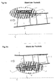
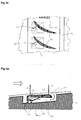
- the 1a schematically shows the section of a fluid flow machine, consisting of a rotor blade row 3 and a stator blade 4. Particularly emphasized is the shroud arrangement at the outer blade end of the rotor 3. According to the prior art, this shroud arrangement consists of a large cavity 10 which is provided in the housing 1 and in which the shroud 2 is completely embedded to provide the smoothest possible outer boundary of the main flow path.
- the 1b shows Also shown is the portion of a fluid flow machine, here consisting of a fixed stator blade row 4 and a rotor blade row 3. Particularly emphasized is the shroud assembly at the inner blade end of the fixed stator 4.
- this shroud assembly consists of a large cavity 10 formed in the hub 8 is provided and in which the shroud 2 is completely embedded to provide the smoothest possible inner boundary of the main flow path.
- FIG. 1C again schematically shows the section of a turbomachine, now consisting of a rotor blade row 3 and a fixed Statorschaufelsch 4 with radial clearance at the hub 8.
- a shroud arrangement at the outer blade end of the stator 4.
- such a shroud arrangement consists of a in the vicinity of the blade leading edge 5 in the housing 1 fixed Statorschaufelfuß 9 and surrounding the downstream part of the blade root 9 large cavity 10, which is provided in the housing 1 and downstream of the blade trailing edge 6 is in communication with the main flow path.
- the housing 1 takes the shroud 2 completely in itself.
- the Fig.1d schematically shows the section of a fluid flow machine, consisting of a series of variable variable stators 4 and a rotor blade row 3. Particularly emphasized is the shroud arrangement on the inner blade end of the Verstellstators 4. According to the prior art, the shroud arrangement consists of a large cavity 10, which in the hub 8 is provided and in which the shroud 2 is completely embedded to provide the smoothest possible inner main flow path boundary.
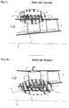
- the 1E shows, representative of shrouds 2 of adjustable or fixed rotors 3 and stators 4, an assembly of components at the edge of the main flow path of a fluid flow machine, consisting of a row of blades with shroud 2 and another structural structure 11 which surrounds said blade shroud 2 and relative to Shroud 2 performs a movement in the circumferential direction of the fluid flow machine. For this reason, located between the shroud 2 and the shroud 2 surrounding the structural structure 11, a cavity 10 in which are provided to reduce the leakage flow sealant 12, which are usually arranged on the side facing away from the main flow path side of the shroud.
- the thick arrow shows the left to right through the blade row 3, 4 running Main flow on
- the thin long arrow indicates the flow path at the edge of the main flow path.
- the arrangement shown here can be both a region on the housing 1 and a region on the hub 8 of a fluid flow machine.
- the shroud 2 may be solid or (not shown here) hollow and consists of one or more components.
- the leakage flow occurring between the shroud 2 and the surrounding structural structure 11 (small arrows), which runs counter to the main flow direction (thick arrow), is reduced in the arrangement shown here by a number of sealing tips 12.
- the sealing tips 12 may be arranged on the surrounding component or even (as not shown here) on the shroud itself.
- the Fig.1f shows, representative of shrouds of adjustable or fixed rotors 3 and stators 4, an arrangement of components at the edge of the main flow path of a fluid flow machine, consisting of a row of blades 3, 4 with shroud 2 and a structural structure 11 which surrounds the said bucket cover 2 and with the blade shroud 2 is locally connected.
- This arrangement is chosen in particular if, downstream of the relevant row of blades 3, 4, fluid is to be removed from the main flow path through a chamber 13 (eg blow-off of air in compressors).
- the bucket cover strip 2 simultaneously forms the blade root 9. In this way, a cavity 10 results, which surrounds the shroud 2 only partially.
- the thick arrow indicates the main flow running from left to right through the blade row 3, 4, the thin long arrow indicates the flow path at the edge of the main flow path.
- the arrangement shown here can be both a region on the housing 1 and a region on the hub 8 of a fluid flow machine.
- the shroud 2 may be solid or (not shown here) hollow and consists of one or several components.
- the cavity 10 is flowed through.
- the leading edge (VK) 5 and trailing edge (HK) 6 of the considered blade row are indicated.
- the cavity 10 surrounding the shroud 2 is connected to the main flow path only directly downstream of the shovel cover strip 2 through an annular gap 14.
- the invention has for its object to provide a flow machine of the type mentioned, which has a high efficiency and is characterized by optimized flow conditions with a simple structure and simple, cost-effective manufacturability.
- the present invention thus relates to blade rows of fluid flow machines such as fans, compressors, pumps and fans of axial, semi-axial or even radial design with gaseous or liquid working medium.
- the turbomachine may include one or more stages, each having a rotor and a stator, in some cases the stage is merely formed by a rotor.
- the rotor consists of a number of blades, which are connected to the rotating shaft of the machine and deliver energy to the working fluid.
- the rotor can be designed with or without shroud on the outer blade end.
- the stator consists of a number fixed blades, which can be designed on the hub side as the housing side with a fixed or free blade end.
- the rotor drum and the blading are usually surrounded by a housing.
- the machine can also have a stator in front of the first rotor, a so-called leading wheel. At least one stator or Vorleitrad - may be rotatably mounted - deviating from the immovable fixation - to change the angle of attack. An adjustment is made for example by a spindle accessible from outside the annular channel.
- said multi-stage turbomachine may have two counterrotating shafts so that the rotor blade rows change direction of rotation from stage to stage. There are no stators between successive rotors.
- the fluid flow machine can alternatively have a bypass configuration such that the single-flow annular channel divides behind a certain row of blades into two concentric annular channels, which in turn accommodate at least one additional row of blades.
- Fig. 2 shows by way of example four possible configurations of the fluid flow machine.
- the present invention comprises designing a shroud of the blade row of a fluid power machine such that a secondary flow path is provided in the blade shroud at at least one location on the circumference which completely penetrates the shroud and thus provides additional connection to the main flow path such that Fluid passes from a zone in the region of the shroud cavity through the shroud to a location on the blade and / or main flow side shroud surface.
- a blade shroud arrangement for use in a turbomachine which additionally influences the course of the flow in the main flow path with the aid of a special passage and in this way increases the power values of the relevant blade row.
- the shroud of a blade row in the present invention is basically characterized in that , when viewed in the meridional flow direction of the turbomachine , at least in the trailing edge region of the meridional Extension of the blade along the main flow path edge on the entire circumference does not make contact with a component surrounding the shroud.
- the thereby formed safeguardsskavtician to the shroud has at least at the downstream boundary of the shroud an annular gap-like connection to the main flow path.
- the cavity surrounding the bucket shroud communicates with the main flowpath at exactly two locations, one behind the other in the meridional flow direction one ring gap directly upstream of the shroud and directly downstream of the shroud, see 1E ,
- the cavity surrounding the bucket shroud communicates with the main flowpath at exactly one location through an annular gap directly downstream of the shroud, see Fig.1f ,
- the purpose of the solution according to the invention is to use the annular cavity around the shroud as a supply source for an additional local fluid supply to the edge and / or blade surfaces of the relevant blade row.
- Inventive shroud configurations are in Fig.3a to Fig.6b shown.
- Decisive for the present invention is the conceptual arrangement of the shroud with a beginning of the Deckbandkavmaschine Sekundärströmungsweg, which penetrates the shroud completely in its further course.
- the exact shape of the shroud cross-sectional shape and the exact geometric design of the boundaries of the shroud cavity can be adapted according to the present circumstances.
- the mentioned features not relevant to the invention are here for the sake of clarity only as far as outlined in a simplified form, as is necessary for the representation and understanding of relevant contexts of the invention.
- the 3a to Fig.3e show by way of example some shroud configurations 2 according to the invention with passage 16.
- the illustration is restricted to the area in the vicinity of the boundary of the main flow path.
- the arrangement comprises a row of blades 3, 4 whose outer end extends to the main flow path edge which is formed at this point by the shroud 2, which is connected to the blades 3, 4 of the blade row.
- the shroud 2 is surrounded by a structural structure 11 in such a way that, at least in part of its extent, a cavity 10, which is in communication with the main flow path, is formed around the shroud 2. Upstream and / or downstream of the row of blades 3, 4 with shroud 2, further rows of blades may be located, but they are not shown here for the sake of simplicity.
- the shroud 2 begins near and upstream of the blade leading edge 5 and terminates near and downstream of the blade trailing edge 6.
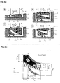
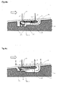
- the Fig. 3a shows the inventive arrangement of a row of blades with shroud 2 in the plane defined by the axial direction x and the radial direction r meridian plane.
- the shroud 2 is given here as a flat, non-stepped, substantially provided with a rectangular cross-section annular body, to which the surrounding structural structure 11 performs a rotating relative movement.
- outgoing sealing tip 12 is provided, which leaves a minimum running gap to the shroud 2 or during operation of the Strömungsarbeitsmaschine also temporarily contact the main flow path side facing away from the shroud 2 optionally with a Anstreifbelag not shown here.
- a secondary flow path 16 is provided in the shroud 2, which penetrates the shroud 2 and seen in the main flow direction (thick arrow from left to right) downstream of the sealant 12 is arranged.
- fluid enters the shroud cavity 10 downstream of the shroud 2 and outflows through the secondary flow path 16, which is here formed as a nozzle-like curved passage 16, to the main flow path-facing side of the shroud 2 (Outflow opening 17) to energize the edge flow there.
- the drawn view ZZ points into the Figures 3c and 3d further features of the invention.
- Fig. 3b shows further variants according to the invention of bucket cover configurations with passage 16 in the meridian view.
- the image part A shows a variant with a fixed connection between blade row 3, 4 and shroud 2, in which the secondary flow path 16 is provided in a flat shroud 2 and forms a nozzle-like curved short passage 16.
- the passage 16 starts on the side of the shroud 2 facing away from the main flow path and ends on the side of the shroud 2 facing the main flow path with an opening 17 projecting into the main flow.
- the image part B shows a variant with a fixed connection between blade row 3, 4 and shroud 2, in which the secondary flow path 16 is provided in a deep shroud 2 and forms a nozzle-like curved long passage 16.
- the passage 16 begins on the downstream side of the shroud 2 and ends on the main flow path-facing side of the shroud 2 with a contour-aligned opening 17th
- the image part C shows a variant with adjusting blades 3, 4 which can be rotated within the shroud 2, in which the secondary flow path 16 is provided in a deep shroud 2 and forms a nozzle-like, curved, long passage 16.
- the passage 16 begins on the side of the shroud 2 facing away from the main flow path and ends on the side of the shroud 2 facing the main flow path with a contour-aligned opening 17.
- the image part D shows a variant with a fixed connection between the blade row 3, 4 and shroud 2, in which the secondary flow path 16 is provided in a deep and waisted shroud 2 and forms a nozzle-like curved long passage 16.
- the passage 16 begins on the downstream side of the shroud 2 and ends on the main flow path-facing side of the shroud 2 with a contour-aligned opening 17th
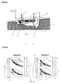
- the Fig. 3c shows the area of a blade end in the view ZZ, ie, the blade passage in the plane spanned by the circumferential direction u and the meridional direction m. Shown are two fluid supply zones, in which, according to the invention, leakage from the secondary flow path 16 to the main flow path-facing side of the shroud 2 is provided. Both zones are substantially supported on the profile suction side: a comprehensive feed zone IA1 in which a feed is advantageous and a further restricted feed zone IA2 located within IA1 in which feed is particularly favorable.
- the 3 d shows the in 3a drawn view ZZ. Shown is a blade row 3, 4, which is represented here by two adjacent blade profiles. The view here falls from the interior of the main flow approximately perpendicular to the meridional direction m and to the circumferential direction u on the shroud 2. Upstream and downstream of the shroud 2, the annular gaps 14 can be seen, which establish a connection between the main flow path and the shroud cavity. In addition, a feed opening 17 is provided in each passage between two blades 3, 4, through which fluid flows out of the shroud 2. An inventively possible form of the passage 16 is shown dotted. According to the invention, a plurality of passages or supply openings per vane passage or passages or supply openings provided in only selected vane passages are also possible.
- the left part of the picture shows an example of an arrangement with short obliquely to Meridianraum m arranged supply openings 17, the right part of the image shows an arrangement with long perpendicular to the meridian m arranged supply openings 17th
- the 3E shows the inventive arrangement of a row of blades 3, 4 with shroud 2 in the plane defined by the axial direction x and the radial direction r meridian plane.
- the shroud 2 is here given as a flat, non-stepped, substantially provided with a rectangular cross-section annular body, which is connected to the surrounding structural structure 11.
- shroud 2 The connection between shroud 2 and surrounding structural structure 11, as shown here, by two adjacent components, for. B. with the help of a blade like footing, be given.
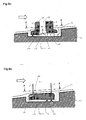
- a secondary flow path 16 is provided in the shroud 2, which penetrates the shroud 2 and seen in the main flow direction (thick arrow from left to right) downstream of the connection with the surrounding structural structure.
- fluid can enter downstream of the shroud 2 in the Deckbandkavtician 10 and flow through the Sekundärströmungsweg, which is here formed as a nozzle-like curved passage 16, on the main flow path side facing the shroud 2 to energize the edge flow there.
- inventive solution shown here of a shroud 2 may be provided with passage 16, if downstream of the relevant blade row 3, 4 additionally an outlet channel for the removal of fluid away from the main flow path of the fluid flow machine exists (dotted lines in the picture). Also plotted is the view ZZ, which in Fig.3f in known manner, an inventive arrangement of supply openings and passages shows.
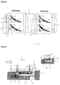
- the Fig. 4a shows a further arrangement according to the invention of a blade row 3, 4 with shroud 2 in the meridian plane.
- the shroud 2 here does not have the usually selected rectangular-like cross-section, but a According to the invention, a particularly advantageous cross-section, graduated in the main flow direction, which allows fluid to be supplied to the passage 16 in the shroud 2 from the shroud downstream side. In this way it is achieved that the inflow to the passage 16 takes place in an enlarged cavity cross section and correspondingly lower loss.
- the passage 16 is shorter and streamlined even in this solution according to the invention, namely as a short close to the supply point arranged curved channel.
- the shroud 2 and the surrounding structural structure 11 perform a rotating relative movement to each other.
- a double sealing tip 12 is provided here.
- the arrangement visible in the drawn view ZZ is similar to the representation in FIG 3 d ,
- the Fig. 4b shows an according to the invention added to other elements arrangement of a blade row 3, 4 with shroud 2 in the meridian plane.
- the shroud 2 also has here according to the invention graduated in the main flow direction cross section with passage inlet 14 at the Abdeckbandabströmseite.
- the shroud 2 and the surrounding structural structure 11 perform a rotating relative movement to each other and to the surrounding structural structure, a deflection means 18 is provided which performs a deflection of the fluid 16 flowing towards the passage.
- the deflection means 18 has the function of an impeller 18 which supplies fluid to the passage 16.
- the deflection means 18 can also be provided on the shroud 2 in order to correct the inflow of the passage 16 with respect to its direction.
- the passage 16 itself may have struts, flow dividers or deflection aids.
- the Fig. 4c shows one of 4b modified form of a solution according to the invention of a shroud 2 with passage 16 and deflection 18.
- the shroud 2 also has here a graduated in the main flow direction cross section with passage inlet 14 at the Abdeckbandabströmseite.
- the shroud 2 and the surrounding structural structure 11 perform a rotating relative movement to each other.
- the contour of the surrounding structural structure 11 in the region of the deflection means 18 and the deflection means 18 themselves are here according to the invention designed that the flow channel formed has a slope / curvature towards the shroud 2 viewed in the direction of the flow in the shroud cavity.
- the inflow of the passage 16 is replaced by a direction component to the shroud 2.
- the shroud 2 projects clearly into the main flow path in order to reduce the amount of leakage flow entering the main flow path by a congestion effect on the upstream side of the shroud 2.
- the Fig. 4d shows one of 4c modified form of a solution according to the invention of a shroud 2 with passage 16 and deflection 18.
- the deflection 18 is provided as a separate and connected to the surrounding structural structure 11 ring member.
- FIG.4E shows the in the FIGS. 4c and 4d drawn view ZZ. Visible are the profiles of the blade row 3, 4 in the main flow path as well as the shroud passages 17, which end at feed openings on the main flow path.
- the deflecting means 18 is formed by a series of curved or non-curved flow profiles or simple webs.
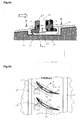
- the Fig. 5a shows a further inventive arrangement of a bucket cover strip 2 with passage 16 in the meridian plane.
- the shroud 2 has a step on the side away from the main flow path, on which two different passages 16 according to the invention begin.
- the shroud 2 is penetrated by a secondary flow path 16, which, as already described above, ends on the mainstream facing side of the shroud 2 (passage type 1), and on the other hand, another secondary flow path 16 leads through the shroud 2 into the interior, at least one connected to the shroud 2 blades 3, 4 (Type 2).
- the blades 3, 4, which receive fluid through the shroud passage 16 of type 2, have one or a plurality of cavities 19, from which the fluid finally exits through one or more openings 20 onto the blade surface wetted by the main flow and is thus supplied to the main flow.
- Details of the fluid routing after passing the passage are known in the art.
- shroud arrangements which alone provide one or more passages of the type 2, according to the invention.
- a passage of the type 2 if this struts, flow dividers or deflection aids.
- the picture shows the view ZZ, which is in 5 b in a known manner, the inventive arrangement of feed openings and passages shows.
- the 5c also shows a shroud arrangement with a combination of Type 1 and 2 Mulasstyp.
- a deflection means 18 is provided, which performs a deflection of the inflowing fluids to the passages.
- the deflection means 18 has the function of an impeller which supplies fluid to the passages.
- the deflecting means 18 may also be provided on the shroud 2 in order to correct the inflow of the passage with respect to its direction.
- the passage itself can have struts, flow dividers or deflection aids.
- the Fig. 6a shows a further inventive concept for the arrangement of a bucket cover strip 2 with passage 16 in the meridian plane.
- the passage 16 starts at the upstream side of the shroud 2 and ends at the main flow-facing side.
- This is a passage of the type 1.
- Particularly favorable for this inventive cover band 2 with passage it is when, as shown here, the shroud 2 protrudes by a significant amount in the main flow path.
- the picture shows the view ZZ, which is in Figure 6b in a known manner, the inventive arrangement of feed openings and passages shows.
Landscapes
- Engineering & Computer Science (AREA)
- Mechanical Engineering (AREA)
- General Engineering & Computer Science (AREA)
- Life Sciences & Earth Sciences (AREA)
- Sustainable Development (AREA)
- Chemical & Material Sciences (AREA)
- Combustion & Propulsion (AREA)
- Structures Of Non-Positive Displacement Pumps (AREA)
Applications Claiming Priority (1)
| Application Number | Priority Date | Filing Date | Title |
|---|---|---|---|
| DE200810029605 DE102008029605A1 (de) | 2008-06-23 | 2008-06-23 | Schaufeldeckband mit Durchlass |
Publications (3)
| Publication Number | Publication Date |
|---|---|
| EP2138727A2 true EP2138727A2 (fr) | 2009-12-30 |
| EP2138727A3 EP2138727A3 (fr) | 2015-11-11 |
| EP2138727B1 EP2138727B1 (fr) | 2019-01-02 |
Family
ID=40651825
Family Applications (1)
| Application Number | Title | Priority Date | Filing Date |
|---|---|---|---|
| EP09005839.7A Not-in-force EP2138727B1 (fr) | 2008-06-23 | 2009-04-27 | Bande de recouvrement d'aube dotée d'un passage |
Country Status (3)
| Country | Link |
|---|---|
| US (1) | US8202039B2 (fr) |
| EP (1) | EP2138727B1 (fr) |
| DE (1) | DE102008029605A1 (fr) |
Cited By (8)
| Publication number | Priority date | Publication date | Assignee | Title |
|---|---|---|---|---|
| EP2581555A1 (fr) * | 2011-10-11 | 2013-04-17 | General Electric Company | Composant de turbomachine présentant une caractéristique de contour d'écoulement |
| US8967959B2 (en) | 2011-10-28 | 2015-03-03 | General Electric Company | Turbine of a turbomachine |
| US8992179B2 (en) | 2011-10-28 | 2015-03-31 | General Electric Company | Turbine of a turbomachine |
| US9051843B2 (en) | 2011-10-28 | 2015-06-09 | General Electric Company | Turbomachine blade including a squeeler pocket |
| EP3599345A1 (fr) * | 2018-07-24 | 2020-01-29 | Safran Aircraft Engines | Ailettes entrefer pour compresseur de turbomachine |
| WO2022069845A1 (fr) * | 2020-10-01 | 2022-04-07 | Safran Aircraft Engines | Aube de turbine pour turbomachine d'aéronef, comprenant une plateforme pourvue d'un canal de réjection de flux primaire vers une cavité de purge |
| FR3114839A1 (fr) * | 2020-10-01 | 2022-04-08 | Safran Aircraft Engines | Aube de turbine pour turbomachine d’aéronef, comprenant une plateforme pourvue d’un canal de réjection de flux primaire en aval de la plateforme |
| FR3120089A1 (fr) * | 2021-02-23 | 2022-08-26 | Safran Aircraft Engines | Distributeur de turbomachine comprenant un conduit de reintroduction de gaz avec une composante tangentielle |
Families Citing this family (24)
| Publication number | Priority date | Publication date | Assignee | Title |
|---|---|---|---|---|
| DE102008011746A1 (de) * | 2008-02-28 | 2009-09-03 | Mtu Aero Engines Gmbh | Vorrichtung und Verfahren zur Umleitung eines Leckagestroms |
| DE102008060424A1 (de) * | 2008-12-04 | 2010-06-10 | Rolls-Royce Deutschland Ltd & Co Kg | Strömungsmaschine mit Seitenwand-Grenzschicht-Barriere |
| FR2960604B1 (fr) * | 2010-05-26 | 2013-09-20 | Snecma | Ensemble a aubes de compresseur de turbomachine |
| GB201013004D0 (en) | 2010-08-03 | 2010-09-15 | Rolls Royce Plc | A seal assembly |
| GB201013003D0 (en) * | 2010-08-03 | 2010-09-15 | Rolls Royce Plc | A seal assembly |
| US8714908B2 (en) * | 2010-11-05 | 2014-05-06 | General Electric Company | Shroud leakage cover |
| US9567942B1 (en) * | 2010-12-02 | 2017-02-14 | Concepts Nrec, Llc | Centrifugal turbomachines having extended performance ranges |
| US9115594B2 (en) * | 2010-12-28 | 2015-08-25 | Rolls-Royce Corporation | Compressor casing treatment for gas turbine engine |
| DE102011107523B4 (de) * | 2011-07-15 | 2016-08-11 | MTU Aero Engines AG | System zum Einblasen eines Fluids, Verdichter sowie Turbomaschine |
| US9255480B2 (en) | 2011-10-28 | 2016-02-09 | General Electric Company | Turbine of a turbomachine |
| US9169849B2 (en) * | 2012-05-08 | 2015-10-27 | United Technologies Corporation | Gas turbine engine compressor stator seal |
| EP2713009B1 (fr) * | 2012-09-26 | 2015-03-11 | Alstom Technology Ltd | Procédé et système de refroidissement pour refroidir des aubes d'au moins une rangée d'aubes dans une turbomachine rotative |
| US9593691B2 (en) * | 2013-07-19 | 2017-03-14 | General Electric Company | Systems and methods for directing a flow within a shroud cavity of a compressor |
| US20150285259A1 (en) * | 2014-04-05 | 2015-10-08 | Arthur John Wennerstrom | Filament-Wound Tip-Shrouded Axial Compressor or Fan Rotor System |
| US9938840B2 (en) | 2015-02-10 | 2018-04-10 | United Technologies Corporation | Stator vane with platform having sloped face |
| US10161250B2 (en) * | 2015-02-10 | 2018-12-25 | United Technologies Corporation | Rotor with axial arm having protruding ramp |
| FR3082558B1 (fr) * | 2018-06-15 | 2021-09-17 | Safran Aircraft Engines | Distributeur de turbine pour turbomachine, comprenant un systeme passif de reintroduction de gaz de fuite dans une veine d'ecoulement des gaz |
| US11499475B2 (en) * | 2018-11-23 | 2022-11-15 | Pratt & Whitney Canada Corp. | Fan assembly having flow recirculation circuit with rotating airfoils |
| JP7356285B2 (ja) | 2019-07-31 | 2023-10-04 | 三菱重工業株式会社 | 軸流タービン |
| CN112211853B (zh) * | 2020-12-07 | 2021-02-12 | 中国航发上海商用航空发动机制造有限责任公司 | 压气机静子缘板前缘构型方法和相应的静子缘板 |
| FR3117532B1 (fr) * | 2020-12-10 | 2024-05-24 | Safran Aircraft Engines | Aube de turbine pour turbomachine d’aéronef, pourvue d’un canal d’éjection de flux primaire vers une cavité inter-léchettes |
| FR3133063B1 (fr) * | 2022-02-25 | 2024-08-02 | Safran Aircraft Engines | Aubage de turbomachine, comprenant une pale et une plateforme qui présente un canal interne d’aspiration et d’éjection de flux |
| US12134974B2 (en) * | 2022-08-04 | 2024-11-05 | General Electric Company | Core air leakage redirection structures for aircraft engines |
| FR3145585B1 (fr) * | 2023-02-06 | 2025-01-10 | Safran Aircraft Engines | Aubage redresseur pour compresseur de turbomachine, compresseur et turbomachine associes |
Family Cites Families (14)
| Publication number | Priority date | Publication date | Assignee | Title |
|---|---|---|---|---|
| GB504214A (en) * | 1937-02-24 | 1939-04-21 | Rheinmetall Borsig Ag Werk Bor | Improvements in and relating to turbo compressors |
| US2291828A (en) * | 1940-05-04 | 1942-08-04 | Westinghouse Electric & Mfg Co | Turbine blading |
| FR2248732A5 (fr) * | 1973-10-23 | 1975-05-16 | Onera (Off Nat Aerospatiale) | |
| US4534701A (en) * | 1982-06-29 | 1985-08-13 | Gerhard Wisser | Rotor or guide wheel of a turbine engine with shroud ring |
| US4642023A (en) * | 1985-07-29 | 1987-02-10 | Rockwell International Corporation | Vented shrouded inducer |
| FR2666846B1 (fr) * | 1990-09-13 | 1992-10-16 | Alsthom Gec | Grille d'aubes pour turbomachine munie de fentes d'aspiration dans le plafond et/ou dans le plancher et turbomachine comportant ces grilles. |
| JPH04132899A (ja) * | 1990-09-25 | 1992-05-07 | Mitsubishi Heavy Ind Ltd | 軸流送風機 |
| US5632598A (en) * | 1995-01-17 | 1997-05-27 | Dresser-Rand | Shrouded axial flow turbo machine utilizing multiple labrinth seals |
| US6632069B1 (en) * | 2001-10-02 | 2003-10-14 | Oleg Naljotov | Step of pressure of the steam and gas turbine with universal belt |
| DE10233032A1 (de) * | 2002-07-20 | 2004-01-29 | Rolls-Royce Deutschland Ltd & Co Kg | Strömungsarbeitsmaschine mit integriertem Fluidzirkulationssystem |
| CA2496543C (fr) * | 2002-08-23 | 2010-08-10 | Mtu Aero Engines Gmbh | Structure de recirculation d'un turbocompresseur |
| DE10355240A1 (de) * | 2003-11-26 | 2005-07-07 | Rolls-Royce Deutschland Ltd & Co Kg | Strömungsarbeitsmaschine mit Fluidentnahme |
| DE102007037855A1 (de) * | 2007-08-10 | 2009-02-12 | Rolls-Royce Deutschland Ltd & Co Kg | Schaufeldeckband mit Sperrstrahlerzeugung |
| DE102008019603A1 (de) * | 2008-04-18 | 2009-10-22 | Rolls-Royce Deutschland Ltd & Co Kg | Strömungsmaschine mit schaufelreiheninterner Fluid-Rückführung |
-
2008
- 2008-06-23 DE DE200810029605 patent/DE102008029605A1/de not_active Withdrawn
-
2009
- 2009-04-27 EP EP09005839.7A patent/EP2138727B1/fr not_active Not-in-force
- 2009-06-23 US US12/489,598 patent/US8202039B2/en not_active Expired - Fee Related
Cited By (16)
| Publication number | Priority date | Publication date | Assignee | Title |
|---|---|---|---|---|
| EP2581555A1 (fr) * | 2011-10-11 | 2013-04-17 | General Electric Company | Composant de turbomachine présentant une caractéristique de contour d'écoulement |
| US8967959B2 (en) | 2011-10-28 | 2015-03-03 | General Electric Company | Turbine of a turbomachine |
| US8992179B2 (en) | 2011-10-28 | 2015-03-31 | General Electric Company | Turbine of a turbomachine |
| US9051843B2 (en) | 2011-10-28 | 2015-06-09 | General Electric Company | Turbomachine blade including a squeeler pocket |
| EP3599345A1 (fr) * | 2018-07-24 | 2020-01-29 | Safran Aircraft Engines | Ailettes entrefer pour compresseur de turbomachine |
| WO2020021200A1 (fr) * | 2018-07-24 | 2020-01-30 | Safran Aircraft Engines | Ailettes entrefer pour compresseur de turbomachine |
| FR3084395A1 (fr) * | 2018-07-24 | 2020-01-31 | Safran Aircraft Engines | Ailettes entrefer pour compresseur de turbomachine |
| US11078801B2 (en) | 2018-07-24 | 2021-08-03 | Safran Aircraft Engines | Air-gap fins for a turbine engine compressor |
| WO2022069845A1 (fr) * | 2020-10-01 | 2022-04-07 | Safran Aircraft Engines | Aube de turbine pour turbomachine d'aéronef, comprenant une plateforme pourvue d'un canal de réjection de flux primaire vers une cavité de purge |
| FR3114838A1 (fr) * | 2020-10-01 | 2022-04-08 | Safran Aircraft Engines | Aube de turbine pour turbomachine d’aéronef, comprenant une plateforme pourvue d’un canal de réjection de flux primaire vers une cavité de purge |
| FR3114839A1 (fr) * | 2020-10-01 | 2022-04-08 | Safran Aircraft Engines | Aube de turbine pour turbomachine d’aéronef, comprenant une plateforme pourvue d’un canal de réjection de flux primaire en aval de la plateforme |
| US12018582B2 (en) | 2020-10-01 | 2024-06-25 | Safran Aircraft Engines | Turbine blade for an aircraft turbine engine, comprising a platform provided with a channel for primary flow rejection towards a purge cavity |
| FR3120089A1 (fr) * | 2021-02-23 | 2022-08-26 | Safran Aircraft Engines | Distributeur de turbomachine comprenant un conduit de reintroduction de gaz avec une composante tangentielle |
| WO2022180322A1 (fr) * | 2021-02-23 | 2022-09-01 | Safran Aircraft Engines | Distributeur de turbomachine comprenant un conduit de reintroduction de gaz avec une composante tangentielle |
| CN116917598A (zh) * | 2021-02-23 | 2023-10-20 | 赛峰飞机发动机公司 | 包括具有切向分量的气体再引入管道的涡轮机分配器 |
| US12281576B2 (en) | 2021-02-23 | 2025-04-22 | Safran Aircraft Engines | Turbomachine distributor comprising a gas reintroduction duct with a tangential component |
Also Published As
| Publication number | Publication date |
|---|---|
| DE102008029605A1 (de) | 2009-12-24 |
| US20090317232A1 (en) | 2009-12-24 |
| EP2138727A3 (fr) | 2015-11-11 |
| EP2138727B1 (fr) | 2019-01-02 |
| US8202039B2 (en) | 2012-06-19 |
Similar Documents
| Publication | Publication Date | Title |
|---|---|---|
| EP2138727B1 (fr) | Bande de recouvrement d'aube dotée d'un passage | |
| EP2110559B1 (fr) | Turbomachine avec réinjection de fluide pour influencer la couche limite | |
| EP2003292B1 (fr) | Machine de travail fluidique avec virole d'aube dotée d'un rebord | |
| EP1382855B1 (fr) | Turbomachine avec système de recirculation de fluide intégré | |
| EP1659293B1 (fr) | Turbomachine | |
| EP2108784B1 (fr) | Turbomachine dotée d'un composant d'injecteur de fluide | |
| EP2096316B1 (fr) | Structuration de boîtier pour compresseur axial dans la zone du moyeu | |
| EP1609999B1 (fr) | Turbo machine | |
| DE60320537T2 (de) | Kompressor mit schaufelspitzeneinrichtung | |
| EP2249044B1 (fr) | Compresseur ou pompe avec extraction de fluide | |
| EP2226510B1 (fr) | Turbo compresseur ou pompe avec injection de fluide pour influencer la couche limite | |
| EP1632662B1 (fr) | Turbomachine avec soutirage | |
| EP2180193B1 (fr) | Turbomachine dotée d'un moyen pour énergiser des bords proches du côté aspirant | |
| DE102007037924A1 (de) | Strömungsarbeitsmaschine mit Ringkanalwandausnehmung | |
| EP2180195A2 (fr) | Turbomachine avec contrôle du jeu des aubes | |
| EP1998049A2 (fr) | Aube de machine de travail d'écoulement doté d'une conception à plusieurs profiles | |
| EP2993356A1 (fr) | Étage de compresseur radial | |
| EP3078804A1 (fr) | Agencement virole pour une rangée d'aubes de rotor ou stator et turbine associée | |
| WO2011124214A2 (fr) | Aube directrice d'une machine d'écoulement | |
| EP3561228B1 (fr) | Aube, segment d'aube et module pour une turbomachine et turbomachine | |
| EP1335136B1 (fr) | Turbine à gaz ayant un compresseur muni d'un système de guidage du flux traversant le canal d'écoulement du compresseur le long des parois de ce canal | |
| WO2016110373A1 (fr) | Soufflante à canal latéral pour un moteur à combustion interne | |
| EP3369892B1 (fr) | Contournage d'une plate-forme de grille d'aube | |
| DE102019220028B4 (de) | Axialturbine | |
| EP0982475A1 (fr) | Turbomachine à écoulement axial avec aubage caréné |
Legal Events
| Date | Code | Title | Description |
|---|---|---|---|
| PUAI | Public reference made under article 153(3) epc to a published international application that has entered the european phase |
Free format text: ORIGINAL CODE: 0009012 |
|
| AK | Designated contracting states |
Kind code of ref document: A2 Designated state(s): AT BE BG CH CY CZ DE DK EE ES FI FR GB GR HR HU IE IS IT LI LT LU LV MC MK MT NL NO PL PT RO SE SI SK TR |
|
| PUAL | Search report despatched |
Free format text: ORIGINAL CODE: 0009013 |
|
| AK | Designated contracting states |
Kind code of ref document: A3 Designated state(s): AT BE BG CH CY CZ DE DK EE ES FI FR GB GR HR HU IE IS IT LI LT LU LV MC MK MT NL NO PL PT RO SE SI SK TR |
|
| AX | Request for extension of the european patent |
Extension state: AL BA RS |
|
| RIC1 | Information provided on ipc code assigned before grant |
Ipc: F01D 5/22 20060101AFI20151002BHEP Ipc: F04D 29/68 20060101ALI20151002BHEP Ipc: F01D 11/00 20060101ALI20151002BHEP Ipc: F04D 27/02 20060101ALI20151002BHEP Ipc: F04D 29/54 20060101ALI20151002BHEP Ipc: F02C 6/08 20060101ALI20151002BHEP |
|
| 17P | Request for examination filed |
Effective date: 20160225 |
|
| RBV | Designated contracting states (corrected) |
Designated state(s): AT BE BG CH CY CZ DE DK EE ES FI FR GB GR HR HU IE IS IT LI LT LU LV MC MK MT NL NO PL PT RO SE SI SK TR |
|
| STAA | Information on the status of an ep patent application or granted ep patent |
Free format text: STATUS: EXAMINATION IS IN PROGRESS |
|
| 17Q | First examination report despatched |
Effective date: 20180215 |
|
| GRAP | Despatch of communication of intention to grant a patent |
Free format text: ORIGINAL CODE: EPIDOSNIGR1 |
|
| STAA | Information on the status of an ep patent application or granted ep patent |
Free format text: STATUS: GRANT OF PATENT IS INTENDED |
|
| INTG | Intention to grant announced |
Effective date: 20180808 |
|
| GRAS | Grant fee paid |
Free format text: ORIGINAL CODE: EPIDOSNIGR3 |
|
| GRAA | (expected) grant |
Free format text: ORIGINAL CODE: 0009210 |
|
| STAA | Information on the status of an ep patent application or granted ep patent |
Free format text: STATUS: THE PATENT HAS BEEN GRANTED |
|
| AK | Designated contracting states |
Kind code of ref document: B1 Designated state(s): AT BE BG CH CY CZ DE DK EE ES FI FR GB GR HR HU IE IS IT LI LT LU LV MC MK MT NL NO PL PT RO SE SI SK TR |
|
| RAP1 | Party data changed (applicant data changed or rights of an application transferred) |
Owner name: ROLLS-ROYCE DEUTSCHLAND LTD & CO KG |
|
| REG | Reference to a national code |
Ref country code: GB Ref legal event code: FG4D Free format text: NOT ENGLISH |
|
| REG | Reference to a national code |
Ref country code: CH Ref legal event code: EP Ref country code: AT Ref legal event code: REF Ref document number: 1084626 Country of ref document: AT Kind code of ref document: T Effective date: 20190115 |
|
| REG | Reference to a national code |
Ref country code: IE Ref legal event code: FG4D Free format text: LANGUAGE OF EP DOCUMENT: GERMAN |
|
| REG | Reference to a national code |
Ref country code: DE Ref legal event code: R096 Ref document number: 502009015538 Country of ref document: DE |
|
| REG | Reference to a national code |
Ref country code: NL Ref legal event code: MP Effective date: 20190102 |
|
| REG | Reference to a national code |
Ref country code: LT Ref legal event code: MG4D |
|
| PG25 | Lapsed in a contracting state [announced via postgrant information from national office to epo] |
Ref country code: NL Free format text: LAPSE BECAUSE OF FAILURE TO SUBMIT A TRANSLATION OF THE DESCRIPTION OR TO PAY THE FEE WITHIN THE PRESCRIBED TIME-LIMIT Effective date: 20190102 |
|
| PG25 | Lapsed in a contracting state [announced via postgrant information from national office to epo] |
Ref country code: FI Free format text: LAPSE BECAUSE OF FAILURE TO SUBMIT A TRANSLATION OF THE DESCRIPTION OR TO PAY THE FEE WITHIN THE PRESCRIBED TIME-LIMIT Effective date: 20190102 Ref country code: NO Free format text: LAPSE BECAUSE OF FAILURE TO SUBMIT A TRANSLATION OF THE DESCRIPTION OR TO PAY THE FEE WITHIN THE PRESCRIBED TIME-LIMIT Effective date: 20190402 Ref country code: PL Free format text: LAPSE BECAUSE OF FAILURE TO SUBMIT A TRANSLATION OF THE DESCRIPTION OR TO PAY THE FEE WITHIN THE PRESCRIBED TIME-LIMIT Effective date: 20190102 Ref country code: LT Free format text: LAPSE BECAUSE OF FAILURE TO SUBMIT A TRANSLATION OF THE DESCRIPTION OR TO PAY THE FEE WITHIN THE PRESCRIBED TIME-LIMIT Effective date: 20190102 Ref country code: PT Free format text: LAPSE BECAUSE OF FAILURE TO SUBMIT A TRANSLATION OF THE DESCRIPTION OR TO PAY THE FEE WITHIN THE PRESCRIBED TIME-LIMIT Effective date: 20190502 Ref country code: ES Free format text: LAPSE BECAUSE OF FAILURE TO SUBMIT A TRANSLATION OF THE DESCRIPTION OR TO PAY THE FEE WITHIN THE PRESCRIBED TIME-LIMIT Effective date: 20190102 Ref country code: SE Free format text: LAPSE BECAUSE OF FAILURE TO SUBMIT A TRANSLATION OF THE DESCRIPTION OR TO PAY THE FEE WITHIN THE PRESCRIBED TIME-LIMIT Effective date: 20190102 |
|
| PG25 | Lapsed in a contracting state [announced via postgrant information from national office to epo] |
Ref country code: LV Free format text: LAPSE BECAUSE OF FAILURE TO SUBMIT A TRANSLATION OF THE DESCRIPTION OR TO PAY THE FEE WITHIN THE PRESCRIBED TIME-LIMIT Effective date: 20190102 Ref country code: HR Free format text: LAPSE BECAUSE OF FAILURE TO SUBMIT A TRANSLATION OF THE DESCRIPTION OR TO PAY THE FEE WITHIN THE PRESCRIBED TIME-LIMIT Effective date: 20190102 Ref country code: BG Free format text: LAPSE BECAUSE OF FAILURE TO SUBMIT A TRANSLATION OF THE DESCRIPTION OR TO PAY THE FEE WITHIN THE PRESCRIBED TIME-LIMIT Effective date: 20190402 Ref country code: IS Free format text: LAPSE BECAUSE OF FAILURE TO SUBMIT A TRANSLATION OF THE DESCRIPTION OR TO PAY THE FEE WITHIN THE PRESCRIBED TIME-LIMIT Effective date: 20190502 Ref country code: GR Free format text: LAPSE BECAUSE OF FAILURE TO SUBMIT A TRANSLATION OF THE DESCRIPTION OR TO PAY THE FEE WITHIN THE PRESCRIBED TIME-LIMIT Effective date: 20190403 |
|
| REG | Reference to a national code |
Ref country code: DE Ref legal event code: R097 Ref document number: 502009015538 Country of ref document: DE |
|
| PG25 | Lapsed in a contracting state [announced via postgrant information from national office to epo] |
Ref country code: DK Free format text: LAPSE BECAUSE OF FAILURE TO SUBMIT A TRANSLATION OF THE DESCRIPTION OR TO PAY THE FEE WITHIN THE PRESCRIBED TIME-LIMIT Effective date: 20190102 Ref country code: CZ Free format text: LAPSE BECAUSE OF FAILURE TO SUBMIT A TRANSLATION OF THE DESCRIPTION OR TO PAY THE FEE WITHIN THE PRESCRIBED TIME-LIMIT Effective date: 20190102 Ref country code: SK Free format text: LAPSE BECAUSE OF FAILURE TO SUBMIT A TRANSLATION OF THE DESCRIPTION OR TO PAY THE FEE WITHIN THE PRESCRIBED TIME-LIMIT Effective date: 20190102 Ref country code: RO Free format text: LAPSE BECAUSE OF FAILURE TO SUBMIT A TRANSLATION OF THE DESCRIPTION OR TO PAY THE FEE WITHIN THE PRESCRIBED TIME-LIMIT Effective date: 20190102 Ref country code: EE Free format text: LAPSE BECAUSE OF FAILURE TO SUBMIT A TRANSLATION OF THE DESCRIPTION OR TO PAY THE FEE WITHIN THE PRESCRIBED TIME-LIMIT Effective date: 20190102 Ref country code: IT Free format text: LAPSE BECAUSE OF FAILURE TO SUBMIT A TRANSLATION OF THE DESCRIPTION OR TO PAY THE FEE WITHIN THE PRESCRIBED TIME-LIMIT Effective date: 20190102 |
|
| PLBE | No opposition filed within time limit |
Free format text: ORIGINAL CODE: 0009261 |
|
| STAA | Information on the status of an ep patent application or granted ep patent |
Free format text: STATUS: NO OPPOSITION FILED WITHIN TIME LIMIT |
|
| REG | Reference to a national code |
Ref country code: CH Ref legal event code: PL |
|
| 26N | No opposition filed |
Effective date: 20191003 |
|
| REG | Reference to a national code |
Ref country code: BE Ref legal event code: MM Effective date: 20190430 |
|
| PG25 | Lapsed in a contracting state [announced via postgrant information from national office to epo] |
Ref country code: MC Free format text: LAPSE BECAUSE OF FAILURE TO SUBMIT A TRANSLATION OF THE DESCRIPTION OR TO PAY THE FEE WITHIN THE PRESCRIBED TIME-LIMIT Effective date: 20190102 Ref country code: LU Free format text: LAPSE BECAUSE OF NON-PAYMENT OF DUE FEES Effective date: 20190427 |
|
| PG25 | Lapsed in a contracting state [announced via postgrant information from national office to epo] |
Ref country code: CH Free format text: LAPSE BECAUSE OF NON-PAYMENT OF DUE FEES Effective date: 20190430 Ref country code: LI Free format text: LAPSE BECAUSE OF NON-PAYMENT OF DUE FEES Effective date: 20190430 |
|
| PG25 | Lapsed in a contracting state [announced via postgrant information from national office to epo] |
Ref country code: BE Free format text: LAPSE BECAUSE OF NON-PAYMENT OF DUE FEES Effective date: 20190430 Ref country code: SI Free format text: LAPSE BECAUSE OF FAILURE TO SUBMIT A TRANSLATION OF THE DESCRIPTION OR TO PAY THE FEE WITHIN THE PRESCRIBED TIME-LIMIT Effective date: 20190102 |
|
| PG25 | Lapsed in a contracting state [announced via postgrant information from national office to epo] |
Ref country code: TR Free format text: LAPSE BECAUSE OF FAILURE TO SUBMIT A TRANSLATION OF THE DESCRIPTION OR TO PAY THE FEE WITHIN THE PRESCRIBED TIME-LIMIT Effective date: 20190102 |
|
| PG25 | Lapsed in a contracting state [announced via postgrant information from national office to epo] |
Ref country code: IE Free format text: LAPSE BECAUSE OF NON-PAYMENT OF DUE FEES Effective date: 20190427 |
|
| REG | Reference to a national code |
Ref country code: AT Ref legal event code: MM01 Ref document number: 1084626 Country of ref document: AT Kind code of ref document: T Effective date: 20190427 |
|
| PGFP | Annual fee paid to national office [announced via postgrant information from national office to epo] |
Ref country code: GB Payment date: 20200429 Year of fee payment: 12 |
|
| PG25 | Lapsed in a contracting state [announced via postgrant information from national office to epo] |
Ref country code: AT Free format text: LAPSE BECAUSE OF NON-PAYMENT OF DUE FEES Effective date: 20190427 |
|
| PG25 | Lapsed in a contracting state [announced via postgrant information from national office to epo] |
Ref country code: CY Free format text: LAPSE BECAUSE OF FAILURE TO SUBMIT A TRANSLATION OF THE DESCRIPTION OR TO PAY THE FEE WITHIN THE PRESCRIBED TIME-LIMIT Effective date: 20190102 |
|
| PG25 | Lapsed in a contracting state [announced via postgrant information from national office to epo] |
Ref country code: HU Free format text: LAPSE BECAUSE OF FAILURE TO SUBMIT A TRANSLATION OF THE DESCRIPTION OR TO PAY THE FEE WITHIN THE PRESCRIBED TIME-LIMIT; INVALID AB INITIO Effective date: 20090427 Ref country code: MT Free format text: LAPSE BECAUSE OF FAILURE TO SUBMIT A TRANSLATION OF THE DESCRIPTION OR TO PAY THE FEE WITHIN THE PRESCRIBED TIME-LIMIT Effective date: 20190102 |
|
| GBPC | Gb: european patent ceased through non-payment of renewal fee |
Effective date: 20210427 |
|
| PG25 | Lapsed in a contracting state [announced via postgrant information from national office to epo] |
Ref country code: GB Free format text: LAPSE BECAUSE OF NON-PAYMENT OF DUE FEES Effective date: 20210427 |
|
| PG25 | Lapsed in a contracting state [announced via postgrant information from national office to epo] |
Ref country code: MK Free format text: LAPSE BECAUSE OF FAILURE TO SUBMIT A TRANSLATION OF THE DESCRIPTION OR TO PAY THE FEE WITHIN THE PRESCRIBED TIME-LIMIT Effective date: 20190102 |
|
| PGFP | Annual fee paid to national office [announced via postgrant information from national office to epo] |
Ref country code: FR Payment date: 20220427 Year of fee payment: 14 Ref country code: DE Payment date: 20220428 Year of fee payment: 14 |
|
| P01 | Opt-out of the competence of the unified patent court (upc) registered |
Effective date: 20230528 |
|
| REG | Reference to a national code |
Ref country code: DE Ref legal event code: R082 Ref document number: 502009015538 Country of ref document: DE |
|
| REG | Reference to a national code |
Ref country code: DE Ref legal event code: R119 Ref document number: 502009015538 Country of ref document: DE |
|
| PG25 | Lapsed in a contracting state [announced via postgrant information from national office to epo] |
Ref country code: FR Free format text: LAPSE BECAUSE OF NON-PAYMENT OF DUE FEES Effective date: 20230430 Ref country code: DE Free format text: LAPSE BECAUSE OF NON-PAYMENT OF DUE FEES Effective date: 20231103 |