EP2103799A2 - Tuyère de fusée et procédé de contrôle du flux de gaz d'échappement dans un moteur à fusée - Google Patents
Tuyère de fusée et procédé de contrôle du flux de gaz d'échappement dans un moteur à fusée Download PDFInfo
- Publication number
- EP2103799A2 EP2103799A2 EP08162393A EP08162393A EP2103799A2 EP 2103799 A2 EP2103799 A2 EP 2103799A2 EP 08162393 A EP08162393 A EP 08162393A EP 08162393 A EP08162393 A EP 08162393A EP 2103799 A2 EP2103799 A2 EP 2103799A2
- Authority
- EP
- European Patent Office
- Prior art keywords
- gas
- nozzle
- rocket
- altitude
- bell
- Prior art date
- Legal status (The legal status is an assumption and is not a legal conclusion. Google has not performed a legal analysis and makes no representation as to the accuracy of the status listed.)
- Granted
Links
- 238000000034 method Methods 0.000 title claims description 15
- 238000002485 combustion reaction Methods 0.000 title description 6
- 239000007789 gas Substances 0.000 claims abstract description 171
- 239000000567 combustion gas Substances 0.000 claims abstract description 49
- 238000011144 upstream manufacturing Methods 0.000 claims abstract description 11
- 239000007800 oxidant agent Substances 0.000 description 35
- 239000000446 fuel Substances 0.000 description 23
- 230000007704 transition Effects 0.000 description 19
- 238000001816 cooling Methods 0.000 description 13
- 230000008859 change Effects 0.000 description 6
- 238000010586 diagram Methods 0.000 description 4
- 239000002828 fuel tank Substances 0.000 description 4
- 230000007246 mechanism Effects 0.000 description 4
- 238000001514 detection method Methods 0.000 description 3
- 230000000694 effects Effects 0.000 description 3
- 230000009467 reduction Effects 0.000 description 2
- 238000004088 simulation Methods 0.000 description 2
- MYMOFIZGZYHOMD-UHFFFAOYSA-N Dioxygen Chemical compound O=O MYMOFIZGZYHOMD-UHFFFAOYSA-N 0.000 description 1
- UFHFLCQGNIYNRP-UHFFFAOYSA-N Hydrogen Chemical compound [H][H] UFHFLCQGNIYNRP-UHFFFAOYSA-N 0.000 description 1
- 230000003111 delayed effect Effects 0.000 description 1
- 239000001257 hydrogen Substances 0.000 description 1
- 229910052739 hydrogen Inorganic materials 0.000 description 1
- 239000007788 liquid Substances 0.000 description 1
- 239000004449 solid propellant Substances 0.000 description 1
Images




Classifications
-
- F—MECHANICAL ENGINEERING; LIGHTING; HEATING; WEAPONS; BLASTING
- F02—COMBUSTION ENGINES; HOT-GAS OR COMBUSTION-PRODUCT ENGINE PLANTS
- F02K—JET-PROPULSION PLANTS
- F02K9/00—Rocket-engine plants, i.e. plants carrying both fuel and oxidant therefor; Control thereof
- F02K9/97—Rocket nozzles
-
- F—MECHANICAL ENGINEERING; LIGHTING; HEATING; WEAPONS; BLASTING
- F02—COMBUSTION ENGINES; HOT-GAS OR COMBUSTION-PRODUCT ENGINE PLANTS
- F02K—JET-PROPULSION PLANTS
- F02K1/00—Plants characterised by the form or arrangement of the jet pipe or nozzle; Jet pipes or nozzles peculiar thereto
- F02K1/38—Introducing air inside the jet
-
- F—MECHANICAL ENGINEERING; LIGHTING; HEATING; WEAPONS; BLASTING
- F02—COMBUSTION ENGINES; HOT-GAS OR COMBUSTION-PRODUCT ENGINE PLANTS
- F02K—JET-PROPULSION PLANTS
- F02K9/00—Rocket-engine plants, i.e. plants carrying both fuel and oxidant therefor; Control thereof
- F02K9/42—Rocket-engine plants, i.e. plants carrying both fuel and oxidant therefor; Control thereof using liquid or gaseous propellants
- F02K9/44—Feeding propellants
- F02K9/46—Feeding propellants using pumps
- F02K9/48—Feeding propellants using pumps driven by a gas turbine fed by propellant combustion gases or fed by vaporized propellants or other gases
-
- F—MECHANICAL ENGINEERING; LIGHTING; HEATING; WEAPONS; BLASTING
- F02—COMBUSTION ENGINES; HOT-GAS OR COMBUSTION-PRODUCT ENGINE PLANTS
- F02K—JET-PROPULSION PLANTS
- F02K9/00—Rocket-engine plants, i.e. plants carrying both fuel and oxidant therefor; Control thereof
- F02K9/42—Rocket-engine plants, i.e. plants carrying both fuel and oxidant therefor; Control thereof using liquid or gaseous propellants
- F02K9/44—Feeding propellants
- F02K9/56—Control
-
- F—MECHANICAL ENGINEERING; LIGHTING; HEATING; WEAPONS; BLASTING
- F02—COMBUSTION ENGINES; HOT-GAS OR COMBUSTION-PRODUCT ENGINE PLANTS
- F02K—JET-PROPULSION PLANTS
- F02K9/00—Rocket-engine plants, i.e. plants carrying both fuel and oxidant therefor; Control thereof
- F02K9/42—Rocket-engine plants, i.e. plants carrying both fuel and oxidant therefor; Control thereof using liquid or gaseous propellants
- F02K9/44—Feeding propellants
- F02K9/56—Control
- F02K9/58—Propellant feed valves
-
- F—MECHANICAL ENGINEERING; LIGHTING; HEATING; WEAPONS; BLASTING
- F02—COMBUSTION ENGINES; HOT-GAS OR COMBUSTION-PRODUCT ENGINE PLANTS
- F02K—JET-PROPULSION PLANTS
- F02K9/00—Rocket-engine plants, i.e. plants carrying both fuel and oxidant therefor; Control thereof
- F02K9/80—Rocket-engine plants, i.e. plants carrying both fuel and oxidant therefor; Control thereof characterised by thrust or thrust vector control
- F02K9/82—Rocket-engine plants, i.e. plants carrying both fuel and oxidant therefor; Control thereof characterised by thrust or thrust vector control by injection of a secondary fluid into the rocket exhaust gases
-
- F—MECHANICAL ENGINEERING; LIGHTING; HEATING; WEAPONS; BLASTING
- F02—COMBUSTION ENGINES; HOT-GAS OR COMBUSTION-PRODUCT ENGINE PLANTS
- F02K—JET-PROPULSION PLANTS
- F02K9/00—Rocket-engine plants, i.e. plants carrying both fuel and oxidant therefor; Control thereof
- F02K9/97—Rocket nozzles
- F02K9/972—Fluid cooling arrangements for nozzles
-
- F—MECHANICAL ENGINEERING; LIGHTING; HEATING; WEAPONS; BLASTING
- F05—INDEXING SCHEMES RELATING TO ENGINES OR PUMPS IN VARIOUS SUBCLASSES OF CLASSES F01-F04
- F05D—INDEXING SCHEME FOR ASPECTS RELATING TO NON-POSITIVE-DISPLACEMENT MACHINES OR ENGINES, GAS-TURBINES OR JET-PROPULSION PLANTS
- F05D2250/00—Geometry
- F05D2250/70—Shape
- F05D2250/71—Shape curved
- F05D2250/713—Shape curved inflexed
Definitions
- the present invention relates to a rocket nozzle and a control method for combustion gas flow in a rocket engine.
- Fig. 1 shows a bell-shaped nozzle 100A as a rocket nozzle.
- a flow path cross-sectional area at a throat 101A is At and a flow path cross-sectional area at a nozzle exit 102A is A1
- an expansion ratio eA of the bell-shaped nozzle 100A is represented by a ratio (A1/At) between A1 and At.
- Fig. 2 shows a bell-shaped nozzle 100B as a rocket nozzle.
- an expansion ratio eB of the bell-shaped nozzle 100B is represented by a ratio (A2/At).
- A2 is greater than A1, and thus eB is greater than eA.
- a specific impulse representing a performance of a rocket nozzle is known.
- the specific impulse varies depending on the expansion ratio and the ambient pressure around the rocket nozzle. Accordingly, the specific impulse changes during the ascent of a rocket.
- Fig. 3 is a graph showing changes of specific impulses with respect to altitude.
- a vertical axis of the graph represents specific impulse and a horizontal axis represents altitude.
- a performance curve 121 shows the change of a specific impulse of the bell-shaped nozzle 100A with respect to altitude.
- a performance curve 122 shows the change of a specific impulse of the bell-shaped nozzle 100B with respect to altitude.
- the performance curve 121 and the performance curve 122 intersect each other at a certain altitude.
- the specific impulse of the bell-shaped nozzle 100A is greater than the specific impulse of the bell-shaped nozzle 100B at an altitude lower than the altitude of intersection, and the specific impulse of the bell-shaped nozzle 100B is greater than the specific impulse of the bell-shaped nozzle 100A at an altitude higher than the altitude of intersection.
- Fig. 4 shows a dual-bell nozzle 110 as a rocket nozzle.
- the dual-bell nozzle 110 includes a first stage nozzle 115 as a portion from a throat 111 to an inflection point 112 and a second stage nozzle 116 as a portion from the inflection point 112 to a nozzle exit 113.
- Each of the first stage nozzle 115 and the second stage nozzle 116 is bell-shaped.
- a flow path cross-sectional area at the throat 111 is represented by At
- a flow path cross-sectional area at the inflection point 112 is represented by A1
- a flow path cross-sectional area at the nozzle exit 113 is represented by A2.
- a flow of combustion gas separates from an inner wall surface of the dual-bell nozzle 110 at the inflection point 112.
- a low expansion flow An expansion ratio of the dual-bell nozzle 110 under the state of the low expansion flow is approximately equal to the expansion ratio of the bell-shaped nozzle 100A.
- the combustion gas flow in the dual-bell nozzle 110 transits from the low expansion flow state to the high expansion flow state at the altitude corresponding to the intersection of the performance curve 121 and the performance curve 122.
- the intersection of the performance curve 121 and the performance curve 122 is referred to as an optimum transition point 120.
- the combustion gas flow in the dual-bell nozzle 110 transits from the low expansion flow state to the high expansion flow state at an altitude much lower than the altitude corresponding to the optimum transition point 120. For that reason, the change of the specific impulse of the dual-bell nozzle 110 with respect to altitude is represented by a performance curve 123.
- the specific impulse of the dual-bell nozzle 110 is reduced at the transition.
- vibration would be strong because the combustion gas flow tends to separate from an inner wall surface of the second stage nozzle 116 at an upstreamposition from the nozzle exit 113 when the altitude is low immediately after the transition.
- An object of the present invention is to provide a rocket nozzle and a control method for combustion gas flow in a rocket engine in which a state of combustion gas flow appropriately transits.
- a rocket nozzle in a first aspect of the present invention, includes a dual-bell nozzle, and a gas introducing section configured to introduce gas into space surrounded by the dual-bell nozzle. Combustion gas flows in the space.
- the dual-bell nozzle includes a first stage nozzle bell-shaped and surrounding an upstreamportion of the space, and a second stage nozzle bell-shaped and surrounding a downstream portion of the space.
- the dual-bell nozzle has an inflection point between the first stage nozzle and the second stage nozzle.
- the gas introducing section includes a first gas inlet provided to a first inner wall surface of the first stage nozzle. The gas is introduced into the space from the first gas inlet.
- a control method for combustion gas flow in a rocket engine includes introducing gas into space surrounded by a dual-bell nozzle. Combustion gas flows in the space.
- the dual-bell nozzle includes a first stage nozzle bell-shaped and surrounding an upstream portion of the space, and a second stage nozzle bell-shaped and surrounding a downstream portion of the space.
- the dual-bell nozzle has an inflection point between the first stage nozzle and the second stage nozzle.
- the gas is introduced into the space from a first gas inlet provided to a first inner wall surface of the first stage nozzle.
- a rocket nozzle and a control method for combustion gas flow in a rocket engine in which a state of combustion gas flow appropriately transits are provided.
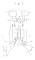
- Fig. 7 shows a rocket engine 1 according to a first embodiment of the present invention.
- the rocket engine 1 includes a fuel tank 2, an oxidizer tank 3, a fuel turbo pump 4, an oxidizer turbo pump 5, and a rocket nozzle 8.
- the fuel turbo pump 4 includes a pump 4a and a turbine 4b which rotates together with the pump 4a.
- the oxidizer turbo pump 5 includes a pump 5a and a turbine 5b which rotates together with the pump 5a.
- the rocket nozzle 8 includes an injector 6, a combustion chamber 7, a dual-bell nozzle 10, and a gas introducing section 40A.
- the combustion chamber 7 is provided with a coolingpath 7a for cooling a wall surface of the combustion chamber 7.
- the dual-bell nozzle 10 includes a first stage nozzle 20 as a portion from a throat 11 to an inflection point 12 and a second stage nozzle 30 as a portion from the inflection point 12 to a nozzle exit 13.
- the inflection point 12 is arranged between the first stage nozzle 20 and the second stage nozzle 30.
- Each of the first stage nozzle 20 and the second stage nozzle 30 is bell-shaped.
- the dual-bell nozzle 10 surrounds space 80.
- the first stage nozzle 20 surrounds an upstream portion 81 of the space 80.
- the second stage nozzle 30 surrounds a downstream portion 82 of the space 80.
- the first stage nozzle 20 may be referred to as a base nozzle.
- the second stage nozzle 30 may be referred
- Manifolds 21 to 23 are provided along a circumference of the first stage nozzle 20. Each of the manifolds 21 to 23 is doughnut-shaped.
- a cooling path 20a for cooling a wall surface of the first stage nozzle 20 is provided to a portion of the first stage nozzle 20 between the manifold 21 and the throat 11.
- the manifold 22 is arranged at a side of the inflection point 12 of the manifold 21 such that the manifold 22 is adjacent to the manifold 21.
- the manifold 23 is arranged between the manifold 22 and the inflection point 12.
- a cooling path 20b for cooling the wall surface of the first stage nozzle 20 is provided to a portion of the first stage nozzle 20 between the manifold 22 and the manifold 23.
- the gas introducing section 40A includes a piping 41 and a manifold 42 provided along the circumference of the first stage nozzle 20.
- the manifold 42 is doughnut-shaped.
- the manifold 42 is arranged at a side of the inflection point 12 of the manifold 23 such that the manifold 42 is adjacent to the manifold 23.
- the piping 41 connects the oxidizer turbo pump 5 and the manifold 42.
- the fuel tank 2 stores fuel such as liquid hydrogen.
- the oxidizer tank 3 stores oxidizer such as liquid oxygen.
- the fuel turbo pump 4 supplies the fuel from the fuel tank 2 to the injector 6.
- the oxidizer turbo pump 5 supplies the oxidizer from the oxidizer tank 3 to the injector 6.
- the injector 6 mixes the fuel and the oxidizer and injects them into the combustion chamber 7.
- the injected fuel and oxidizer are ignited to produce combustion gas.
- the combustion gas flows into the space 80 through the throat 11 from the combustion chamber 7.
- the combustion gas passes the upstream portion 81 and the downstream portion 82 in this order and outflows from the nozzle exit 13.
- the fuel turbo pump 4 supplies the fuel also to the manifold 21 from the fuel tank 2.
- the fuel enters the manifold 22 from the manifold 21 after passing the cooling path 20a and the cooling path 7a in this order.
- the fuel enters the manifold 23 through the cooling path 20b from the manifold 22 and is fed to the fuel turbo pump 4 from the manifold 23.
- the fuel drives the fuel turbo pump 4 and the oxidizer turbo pump 5.
- Turbine exhaust gas as the fuel after driving the fuel turbo pump 4 and the oxidizer turbo pump 5 flows into the manifold 42 through the piping 41.
- the gas introducing section 40A introduces the turbine exhaust gas into the space 80 to control the combustion gas flow.
- the gas introducing section 40A includes an inlet 45 provided to an inner wall surface of the first stage nozzle 20 and an introduction path 43 connecting the manifold 42 and the inlet 45.
- the inlet 45 is arranged at the upstream side of the inflection point 12.
- the introduction path 43 includes a tapered portion 44 of which a flow path cross-sectional area reduces toward the inlet 45.
- the turbine exhaust gas having flowed into the manifold 42 is injected into the space 80 from the inlet 45 through the introduction path 43.
- the turbine exhaust gas is accelerated when passing the tapered portion 44.
- the inlet 45 injects the turbine exhaust gas as a film-like flow along the inner wall surface of the first stage nozzle 20 toward the inflection point 12.
- the turbine exhaust gas being ejected from the inlet 45 as a film-like flow prevents the combustion gas flowing in the space 80 from transiting to the high expansion flow state at an earlier timing (lower altitude) than the optimum point.
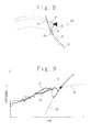
- Fig. 9 is a graph showing a change with time of a performance (the specific impulse) after a liftoff.
- a vertical axis of the graph represents the performance (specific impulse) and a horizontal axis represents time from the liftoff.
- a performance curve 131 shows the change with time of the performance (specific impulse) of the rocket nozzle 8 in case of the low expansion flow state in which the combustion gas flow separates at the inflection point 12.
- a performance curve 132 shows the change with time of the performance (specific impulse) of the rocket nozzle 8 in case of the high expansion flow state in which the combustion gas flow separates at the nozzle exit 13.
- a performance curve 133 shows a simulation result of the performance of the rocket nozzle 8 in case that the turbine exhaust gas is not introduced into the space 80 from the inlet 45.
- a performance curves 134 shows a simulation result of the performance of the rocket nozzle 8 in case that the turbine exhaust gas is introduced into the space 80 from the inlet 45.
- the timing of the transition from the low expansion flow state to the high expansion flow state is delayed and is controlled to be near the optimum transition point 130.
- the timing of the transition is controlled to be near the optimum transition point 130, the magnitude of the reduction of the specific impulse at the transition is small and vibration immediately after the transition is suppressed.
- a rocket engine 1 according to a second embodiment of the present invention is configured as same as the rocket engine 1 according to the first embodiment except that the gas introducing section 40A is replaced by a gas introducing section 40B.
- the gas introducing section 40B includes, in addition to the piping 41, the manifold 42, the introduction path 43 and the inlet 45 which are described above, an exhaust pipe 46 branched from the piping 41 and a valve 47 provided to the exhaust pipe 46.
- the valve 47 opens and closes based on a control signal 71.
- a part of the turbine exhaust gas from the oxidizer turbo pump 5 is introduced into the space 80 from the inlet 45 and the remaining is exhausted to the atmosphere through the exhaust pipe 46.
- the valve 47 is close, the whole of the turbine exhaust gas from the oxidizer turbo pump 5 is introduced into the space 80 from the inlet 45.
- An altitude H of the rocket including the rocket engine 1 is monitored.
- the rocket lifts off in a state in which the valve 47 is open. After that, the valve 47 is kept open until it is detected that the altitude H exceeds a predetermined altitude H1.
- the altitude H1 is determined based on an altitude at which the performance curve 133 diverges from the performance curve 131. Since the ambient pressure around the rocket is sufficiently high at the liftoff and immediately after the liftoff, the combustion gas flow is kept in the low expansion flow state even when the flow rate of the turbine exhaust gas introduced into the space 80 from the inlet 45 is small.
- the valve 47 closes when it is detected that the altitude H exceeds the altitude H1. After that, the valve 47 is kept close until it is detected that the altitude H exceeds a predetermined altitude H2.
- the altitude H2 is determined based on the optimum transition point 130 described above.
- the altitude H2 is higher than the altitude H1.
- the flow rate of the turbine exhaust gas introduced into the space 80 from the inlet 45 is controlled to be large. Accordingly, the flow of the turbine exhaust gas is kept in the low expansion flow state.
- the valve 47 opens when it is detected that the altitude H exceeds the altitude H2. After that, the valve 47 is kept open. The transition of the combustion gas from the low expansion flow state to the high expansion flow state is promoted by opening the valve 47 to reduce the flow rate of the turbine exhaust gas introduced into the space 80 from the inlet 45.
- the valve 47 can be close during a period from the liftoff to the detection of the altitude H exceeding the altitude H1, however, it is expected that the combustion gas flow immediately after the ignition is stabilized by opening the valve 47 to reduce the flow rate of the turbine exhaust gas introduced into the space 80 from the inlet 45.
- a rocket engine 1 according to a third embodiment of the present invention is configured as same as the rocket engine 1 according to the first embodiment except that the gas introducing section 40A is replaced by a gas introducing section 40C.
- the gas introducing section 40C includes, in addition to the piping 41, the manifold 42, the introduction path 43 and the inlet 45 which are described above, a three-way valve 51 provided to the piping 41 and a manifold 52 arranged at a side of the inflection point 12 of the manifold 42 such that the manifold 52 is adjacent to the manifold 42.
- the three-way valve 51 connects one of them to the oxidizer turbo pump 5.
- the turbine exhaust gas from the oxidizer turbo pump 5 flows into the manifold 42 or the manifold 52 depending on a state of the switching of the three-way valve 51.
- the manifold 52 is provided along the circumference of the first stage nozzle 20 (or the inflection point 12).
- the manifold 52 is doughnut-shaped.
- the gas introducing section 40C includes an inlet 55 provided to the inner wall surface of the second stage nozzle 30 and an introduction path 53 connecting the manifold 52 and the inlet 55.
- the introduction path 53 includes a tapered portion 54 of which a flow path cross-sectional area reduces toward the inlet 55.
- the turbine exhaust gas having flowed into the manifold 52 is injected into the space 80 from the inlet 55 through the introduction path 53.
- the turbine exhaust gas is accelerated when passing the tapered portion 54.
- the inlet 55 injects the turbine exhaust gas as a film-like flow along the inner wall surface of the second stage nozzle 30 toward the nozzle exit 13.
- the altitude H of the rocket is monitored.
- the rocket lifts off in a state in which the three-way valve 51 connects the manifold 52 and the oxidizer turbo pump 5.
- the manifold 52 is connected to the oxidizer turbo pump 5
- the inlet 55 is connected to the oxidizer turbo pump 5.
- the three-way valve 51 keeps connecting the manifold 52 and the oxidizer turbo pump 5 until it is detected that the altitude H exceeds the altitude H1 described above. Since the ambient pressure around the rocket is sufficiently high at the liftoff and immediately after the liftoff, the combustion gas flow is kept in the low expansion flow state even when the turbine exhaust gas is not introduced into the space 80 from the inlet 45 at the upstream side of the inflection point 12.
- the three-way valve 51 switches from the state of connecting the manifold 52 and the oxidizer turbo pump 5 to the state of connecting the manifold 42 and the oxidizer turbo pump 5. After that, the three-way valve 51 keeps the state of connecting the manifold 42 and the oxidizer turbo pump 5 until it is detected that the altitude H exceeds the predetermined altitude H2.
- the manifold 42 is connected to the oxidizer turbo pump 5
- the inlet 45 is connected to the oxidizer turbo pump 5.
- the turbine exhaust gas flows from the oxidizer turbo pump 5 to the inlet 45 through the manifold 42 and is introduced into the space 80. Accordingly, the flow of the turbine exhaust gas is kept in the low expansion flow state.
- the three-way valve 51 switches from the state of connecting the manifold 42 and the oxidizer turbo pump 5 to the state of connecting the manifold 52 and the oxidizer turbo pump 5. After that, the three-way valve 51 keeps the state of connecting the manifold 52 and the oxidizer turbo pump 5.
- the transition of the turbine exhaust gas from the low expansion flow state to the high expansion flow state of the combustion gas is promoted by stopping the introduction into the space 80 from the inlet 45 with the three-way valve 51.
- the turbine exhaust gas flows from the oxidizer turbo pump 5 to the inlet 55 through the manifold 52 and is introduced into the space 80. Accordingly, the inner wall surface of the second stage nozzle 30 is film-cooled.
- the three-way valve 51 can be kept in the state of connecting the manifold 42 and the oxidizer turbo pump 5 during a period from the liftoff to the detection of the altitude H exceeding the altitude H1, however, it is expected that the combustion gas flow immediately after the ignition is stabilized by keeping the state of connecting the manifold 52 and the oxidizer turbo pump 5.
- a rocket engine 1 according to a fourth embodiment of the present invention is configured as same as the rocket engine 1 according to the first embodiment except that the gas introducing section 40A is replaced by a gas introducing section 40D and that the wall surface of the second stage nozzle 30 is cooled by the fuel before driving the fuel turbo pump 4 and the oxidizer turbo pump 5.
- a manifold 24 is provided along the circumference of the first stage nozzle 20.
- the manifold 24 is arranged between the manifold 23 and the inflection point 12.
- the manifold 23 and the manifold 24 are connected each other by a piping 48 provided outside of the dual-bell nozzle 10.
- a manifold 31 is provided along the nozzle exit 13.
- Each of the manifolds 24 and 31 is doughnut-shaped.
- the second stage nozzle 30 is provided with a cooling path 30a for cooling the wall surface of the second stage nozzle 30.
- the fuel having entered the manifold 23 through the cooling path 20b enters the manifold 24 through the piping 48.
- the fuel enters the manifold 31 through the cooling path 30a and is fed from the manifold 31 to the turbine 4b of the fuel turbo pump 4.
- the fuel is exhausted after driving the fuel turbo pump 4 and the oxidizer turbo pump 5.
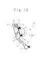
- the gas introducing section 40D includes an air intake 62 provided to an outer wall surface of the first stage nozzle 20, an inlet 63 provided to the inner wall surface of the first stage nozzle 20, an air path 61 connecting the air intake 62 and the inlet 63, a slider 64, and a drive mechanism 65.
- the slider 64 is driven by the drive mechanism 65 to open and close the air intake 62.
- the inlet 63 is arranged at the upstream side of the inflection point 12.
- the altitude H of the rocket is monitored.
- the rocket lifts off in a state in which the slider 64 is arranged at a position to close the air intake 62. After that, the slider 64 is kept at the position to close the air intake 62 until it is detected that the altitude H exceeds the altitude H1 described above. Since the ambient pressure around the rocket is sufficiently high at the liftoff and immediately after the liftoff, the combustion gas flow is kept in the low expansion flow state even when air is not introduced into the space 80 from the inlet 63.
- the drive mechanism 65 slides the slider 64 to a position not to close the air intake 62. After that, the slider 64 is kept at the position not to close the air intake 62 until it is detected that the altitude H exceeds the altitude H2 described above.
- the rocket ascends from the altitude H1 to the altitude H2, air is introduced into the space 80 from the inlet 63. Accordingly, the flow of the turbine exhaust gas is kept in the low expansion flow state.
- the drive mechanism 65 slides the slider 64 to the position to close the air intake 62.
- the transition of the combustion gas from the low expansion flow state to the high expansion flow state is promoted, by stopping the introduction of air into the space 80 from the inlet 63.
- the slider 64 is kept at the position to close the air intake 62.
- the combustion gas is prevented from leaking to the outside through the air path 61.
- the slider 64 can be kept at the position not to close the air intake 62 during a period from the liftoff to the detection of the altitude H exceeding the altitude H1, however, it is expected that the combustion gas flow immediately after the ignition is stabilized by closing the air intake 62.
- the gas introducing section 40D can be applied to a solid-fuel rocket.
- the wall surface of the second stage nozzle 30 can be film-cooled.
- gas introducing sections 40A to 40D are effective in reentry of the rocket into the atmosphere.
- the transition timing can be controlled more precisely by controlling, based on the altitude H of the rocket, the flow rate of the gas introduced into the space 80 from the inlet 45 or 63 provided to the inner wall surface of the first stage nozzle 20.
- a rocket nozzle includes a dual-bell nozzle (10) and a gas introducing section (40A, 40B, 40C, 40D) configured to introduce gas into space (80) surrounded by the dual-bell nozzle. Combustion gas flows in the space.
- the dual-bell nozzle includes a first stage nozzle (20) bell-shaped and surrounding an upstream portion (81) of the space, and a second stage nozzle (30) bell-shaped and surrounding a downstream portion (82) of the space.
- the dual-bell nozzle has an inflection point (12) between the first stage nozzle and the second stage nozzle.
- the gas introducing section includes a first gas inlet (45, 63) provided to a first inner wall surface of the first stage nozzle. The gas is introduced into the space from the first gas inlet.
- turbine exhaust gas after driving a turbo pump (4, 5) is used as the gas.
- the first gas inlet injects the gas as a film-like flow along the first inner wall surface.
- the gas introducing section includes a first manifold (42) provided along a circumference of the first stage nozzle, and a first path (43) connecting the first manifold and the first inlet.
- the first path includes a portion (44) of which a flow path cross-sectional area reduces toward the first inlet.
- the turbine exhaust gas flows into the manifold from the turbo pump and flows to the first inlet through the first path.
- the gas introducing section includes a piping (41) connecting the turbo pump and the first manifold, an exhaust pipe (46) branched from the piping, and a valve (47) provided to the exhaust pipe.
- valve operates based on an altitude of a rocket including the rocket nozzle.
- the gas introducing section includes a second gas inlet (55) provided to a second inner wall surface of the second stage nozzle, and a three-way valve (51).
- a second gas inlet (55) provided to a second inner wall surface of the second stage nozzle, and a three-way valve (51).
- Each of the first gas inlet, the second gas inlet and the turbo pump is connected to the three-way valve.
- the second gas inlet injects the turbine exhaust gas as a film-like flow along the second inner wall surface.
- the three-way valve switches between the first gas inlet and the second gas inlet to connect one of the first gas inlet and the second gas inlet to the turbo pump.
- the gas introducing section includes an air intake (62) provided to an outer wall surface of the first stage nozzle, an air path (61) connecting the air intake and the first gas inlet, and a slider (64) configured to open and close the air intake.
- a control method for combustion gas flow in a rocket engine includes introducing gas into space (80) surrounded by a dual-bell nozzle (10). Combustion gas flows in the space.
- the dual-bell nozzle includes a first stage nozzle (20) bell-shaped and surrounding an upstream portion (81) of the space, and a second stage nozzle (30) bell-shaped and surrounding a downstream portion (82) of the space.
- the dual-bell nozzle has an inflection point (12) between the first stage nozzle and the second stage nozzle.
- the gas is introduced into the space from a first gas inlet (45, 63) provided to a first inner wall surface of the first stage nozzle.
- flow rate of the gas is controlled based on an altitude of a rocket including the dual-bell nozzle.
- turbine exhaust gas after driving a turbo pump (4, 5) is used as the gas.
- An exhaust pipe (46) is branched from a piping (41) for introducing the turbine exhaust gas from the turbo pump to the first gas inlet.
- a valve (47) is provided to the exhaust pipe. In the introducing the gas, it is preferable that the valve having been close opens when it is detected that the altitude of the rocket exceeds a first altitude.
- the rocket lifts off in a state that the valve is open.
- the valve having been open closes when it is detected that the altitude of the rocket exceeds a second altitude lower than the first altitude.
- turbine exhaust gas after driving a turbo pump (4, 5) is used as the gas.
- a second gas inlet (55) is provided to a second inner wall surface of the second stage nozzle. The second gas inlet injects the turbine exhaust gas as a film-like flow along the second inner wall surface.
- Each of the first gas inlet and the second gas inlet is connected to the turbo pump through a three-way valve (51).
- the three-way valve switches from a first state to allow the exhaust gas to flow to the first gas inlet to a second state to allow the exhaust gas to flow to the second gas inlet when it is detected that the altitude of the rocket exceeds a first altitude.
- the rocket lifts off with the three-way valve being in the second state.
- the three-way valve switches from the second state to the first state when it is detected that the altitude of the rocket exceeds a second altitude lower than the first altitude.
- the first gas inlet is connected through an air path (61) to an air intake (62) provided to an outer wall surface of the first stage nozzle.
- a slider (64) slides from a first position not to close the air intake to a second position to close the air intake when it is detected that the altitude of the rocket exceeds a first altitude.
- the rocket lifts off in a state that the slider is arranged at the second position.
- the slider slides from the second position to the first position when it is detected that the altitude of the rocket exceeds a second altitude lower than the first altitude.
Landscapes
- Engineering & Computer Science (AREA)
- Chemical & Material Sciences (AREA)
- Combustion & Propulsion (AREA)
- Mechanical Engineering (AREA)
- General Engineering & Computer Science (AREA)
- Testing Of Engines (AREA)
Applications Claiming Priority (1)
| Application Number | Priority Date | Filing Date | Title |
|---|---|---|---|
| JP2008069502A JP4672747B2 (ja) | 2008-03-18 | 2008-03-18 | ロケットノズル及びロケットエンジン燃焼ガス流れの制御方法 |
Publications (3)
| Publication Number | Publication Date |
|---|---|
| EP2103799A2 true EP2103799A2 (fr) | 2009-09-23 |
| EP2103799A3 EP2103799A3 (fr) | 2013-06-26 |
| EP2103799B1 EP2103799B1 (fr) | 2018-05-23 |
Family
ID=39768636
Family Applications (1)
| Application Number | Title | Priority Date | Filing Date |
|---|---|---|---|
| EP08162393.6A Not-in-force EP2103799B1 (fr) | 2008-03-18 | 2008-08-14 | Tuyère de fusée et procédé de contrôle du flux de gaz d'échappement dans un moteur à fusée |
Country Status (6)
| Country | Link |
|---|---|
| US (1) | US8220249B2 (fr) |
| EP (1) | EP2103799B1 (fr) |
| JP (1) | JP4672747B2 (fr) |
| KR (1) | KR101131267B1 (fr) |
| CN (1) | CN101539074B (fr) |
| RU (1) | RU2383769C1 (fr) |
Cited By (8)
| Publication number | Priority date | Publication date | Assignee | Title |
|---|---|---|---|---|
| RU2476706C1 (ru) * | 2011-09-21 | 2013-02-27 | Николай Борисович Болотин | Жидкостный ракетный двигатель |
| RU2476709C1 (ru) * | 2011-11-25 | 2013-02-27 | Николай Борисович Болотин | Жидкостный ракетный двигатель |
| RU2476708C1 (ru) * | 2011-11-25 | 2013-02-27 | Николай Борисович Болотин | Жидкостный ракетный двигатель |
| FR2981127A1 (fr) * | 2011-10-11 | 2013-04-12 | Snecma | Dispositif de propulsion a reaction et procede d'alimentation |
| FR2991391A1 (fr) * | 2012-05-30 | 2013-12-06 | Snecma | Dispositif et procede d'alimentation d'une chambre propulsive de moteur-fusee |
| FR2992364A1 (fr) * | 2012-06-25 | 2013-12-27 | Snecma | Turbopompe |
| US9849533B2 (en) | 2013-05-30 | 2017-12-26 | General Electric Company | Hybrid diffusion-brazing process and hybrid diffusion-brazed article |
| WO2019202269A1 (fr) | 2018-04-18 | 2019-10-24 | Centre National De La Recherche Scientifique | Contrôle de transition de régime et de vectorisation de poussée dans une tuyère à galbe multiple par injection secondaire |
Families Citing this family (26)
| Publication number | Priority date | Publication date | Assignee | Title |
|---|---|---|---|---|
| CN102980775B (zh) * | 2012-11-30 | 2015-02-25 | 中国航天空气动力技术研究院 | 一种用于高空模拟试车台的喷水冷却装置 |
| JP6045389B2 (ja) | 2013-02-18 | 2016-12-14 | 三菱重工業株式会社 | タービンノズル及びその製造方法 |
| FR3009029B1 (fr) * | 2013-07-26 | 2018-03-23 | Astrium Sas | Tuyere d'ejection de gaz de combustion d'un moteur fusee pourvue d'un dispositif d'etancheite entre une partie fixe et une partie mobile de la tuyere |
| CN104615807B (zh) * | 2014-12-26 | 2018-07-06 | 中国航天科技集团公司第六研究院第十一研究所 | 一种多机并联液体火箭发动机结构低频的仿真方法 |
| JP6615569B2 (ja) * | 2015-10-26 | 2019-12-04 | 三菱重工業株式会社 | ロケットノズル及びこれを備えたロケットエンジン |
| US11181076B2 (en) | 2016-03-03 | 2021-11-23 | Kevin Michael Weldon | Rocket engine bipropellant supply system including an electrolyzer |
| CN109630317B (zh) * | 2018-12-06 | 2021-05-04 | 上海空间推进研究所 | 基于电动泵的轨姿控一体化空间推进系统 |
| CN109654539B (zh) * | 2018-12-07 | 2020-09-18 | 中国航发沈阳发动机研究所 | 一种干低排放燃气涡轮发动机燃烧室 |
| RU2719802C1 (ru) * | 2019-02-14 | 2020-04-23 | Российская Федерация, от имени которой выступает ФОНД ПЕРСПЕКТИВНЫХ ИССЛЕДОВАНИЙ | Способ управления пулей и управляемая пуля |
| RU2719801C1 (ru) * | 2019-02-14 | 2020-04-23 | Российская Федерация, от имени которой выступает ФОНД ПЕРСПЕКТИВНЫХ ИССЛЕДОВАНИЙ | Управляемая пуля |
| US20200263636A1 (en) * | 2019-02-19 | 2020-08-20 | M&J Engineering P.C. | Thrust Augmentation for Liquid Rocket Engines |
| CN110450941B (zh) * | 2019-07-02 | 2020-11-24 | 杭州电子科技大学 | 一种基于气囊的快速驱动装置及其驱动方法 |
| CN110514260B (zh) * | 2019-07-26 | 2021-02-09 | 上海空间推进研究所 | 适用于火箭发动机喷注器边区流量的测量设备及方法 |
| CN111042950A (zh) * | 2019-12-31 | 2020-04-21 | 西北工业大学 | 电机泵辅助调速式涡轮泵供应系统 |
| CN111794878A (zh) * | 2020-08-06 | 2020-10-20 | 北京环境特性研究所 | 一种火箭发动机冷却与隐身设计装置 |
| KR102469946B1 (ko) * | 2020-12-31 | 2022-11-23 | 한국항공우주연구원 | 연소기 헤드-터보펌프 일체형 로켓엔진 |
| CN113266492B (zh) * | 2021-04-16 | 2022-03-15 | 北京星际荣耀空间科技股份有限公司 | 发动机推力室、火箭发动机、液体火箭 |
| CN114455105B (zh) * | 2022-04-13 | 2022-09-13 | 国科大杭州高等研究院 | 一种微牛级宝石基双气容变推力闭环冷气推力器及其运行方法 |
| KR102793784B1 (ko) * | 2022-08-04 | 2025-04-11 | 한국항공우주연구원 | 로켓추진기관 |
| US12209558B2 (en) * | 2022-10-14 | 2025-01-28 | Innovative Rocket Technologies, Inc. | Rocket engine with dual contour nozzle |
| US12025079B2 (en) * | 2022-10-14 | 2024-07-02 | Innovative Rocket Technologies Inc. | Rocket engine with dual contour nozzle |
| CN115949532A (zh) * | 2022-11-21 | 2023-04-11 | 北京航天动力研究所 | 一种分级预冷却单壁喷管延伸段 |
| AU2024319354A1 (en) * | 2023-08-10 | 2025-10-30 | Stoke Space Technologies, Inc. | Heat shield with recessed dual-expansion nozzle, and vehicle including the same |
| US12180914B1 (en) | 2023-08-28 | 2024-12-31 | Pivotal Space, Inc. | Boost injection turbine exhaust cycle (BITEC) |
| US11976613B1 (en) | 2023-08-28 | 2024-05-07 | Pivotal Space, Inc. | Dual mode rocket engine with bipropellant injection in the nozzle |
| US11976614B1 (en) * | 2023-08-28 | 2024-05-07 | Pivotal Space, Inc. | Afterburning turbine exhaust cycle (ABTEC) |
Family Cites Families (18)
| Publication number | Priority date | Publication date | Assignee | Title |
|---|---|---|---|---|
| FR1139802A (fr) * | 1955-11-29 | 1957-07-05 | Perfectionnement aux tuyauteries ou aux canaux parcourus par des fluides | |
| US3212259A (en) * | 1962-11-19 | 1965-10-19 | Kepler Charles Edward | Tertiary flow injection thrust vectoring system |
| FR1367366A (fr) * | 1963-08-28 | 1964-07-17 | Thiokol Chemical Corp | Dispositif de commande des fusées |
| US3394549A (en) * | 1965-07-06 | 1968-07-30 | North American Rockwell | Step nozzle |
| FR1489062A (fr) * | 1966-04-15 | 1967-07-21 | Snecma | Propulseur combiné à statoréacteur et fusée |
| US3469787A (en) * | 1966-09-07 | 1969-09-30 | Thiokol Chemical Corp | Rocket motor thrust nozzle with means to direct atmospheric air into the interior of the nozzle |
| US3698642A (en) * | 1966-11-04 | 1972-10-17 | Thiokol Chemical Corp | Thrust vector control system |
| DE1626082B1 (de) * | 1967-07-26 | 1970-06-25 | Erno Raumfahrttechnik Gmbh | Raketentriebwerk fuer fluessige treibstoffe |
| US3925982A (en) * | 1973-09-11 | 1975-12-16 | Martin Marietta Corp | Fluid-dynamic shock ring for controlled flow separation in a rocket engine exhaust nozzle |
| DE2949522C2 (de) | 1979-12-08 | 1982-01-28 | Messerschmitt-Bölkow-Blohm GmbH, 8000 München | Gekühlte Schubdüse für ein Raketentriebwerk |
| US4815279A (en) * | 1985-09-27 | 1989-03-28 | The United States Of America As Represented By The National Aeronautics And Space Administration | Hybrid plume plasma rocket |
| FR2618488B1 (fr) * | 1987-07-20 | 1989-12-15 | Europ Propulsion | Divergent a rupture de galbe pour tuyere de moteur-fusee |
| FR2628790A1 (fr) * | 1988-03-16 | 1989-09-22 | Snecma | Propulseur combine turbofusee aerobie |
| FR2639404B1 (fr) * | 1988-11-21 | 1994-04-15 | Propulsion Ste Europeenne | Divergent de moteur-fusee a tuyere annulaire complementaire |
| RU2095609C1 (ru) * | 1989-08-03 | 1997-11-10 | Конструкторское бюро "Химавтоматики" | Сопло камеры жидкостного ракетного двигателя |
| WO1998012429A1 (fr) | 1996-09-23 | 1998-03-26 | Volvo Aero Corporation | Tuyere de fusee a temperature regulee |
| JPH1182173A (ja) | 1997-09-02 | 1999-03-26 | Fuji Heavy Ind Ltd | エゼクタロケット |
| US6983587B2 (en) * | 2002-10-28 | 2006-01-10 | James Shumate | Method and apparatus for thrust augmentation for rocket nozzles |
-
2008
- 2008-03-18 JP JP2008069502A patent/JP4672747B2/ja not_active Expired - Fee Related
- 2008-08-14 EP EP08162393.6A patent/EP2103799B1/fr not_active Not-in-force
- 2008-08-28 US US12/200,265 patent/US8220249B2/en not_active Expired - Fee Related
- 2008-08-28 KR KR1020080084195A patent/KR101131267B1/ko not_active Expired - Fee Related
- 2008-08-28 RU RU2008135216/06A patent/RU2383769C1/ru not_active IP Right Cessation
- 2008-08-29 CN CN2008102149301A patent/CN101539074B/zh not_active Expired - Fee Related
Cited By (14)
| Publication number | Priority date | Publication date | Assignee | Title |
|---|---|---|---|---|
| RU2476706C1 (ru) * | 2011-09-21 | 2013-02-27 | Николай Борисович Болотин | Жидкостный ракетный двигатель |
| US9771897B2 (en) | 2011-10-11 | 2017-09-26 | Snecma | Jet propulsion device and fuel supply method |
| FR2981127A1 (fr) * | 2011-10-11 | 2013-04-12 | Snecma | Dispositif de propulsion a reaction et procede d'alimentation |
| WO2013054027A1 (fr) * | 2011-10-11 | 2013-04-18 | Snecma | Dispositif de propulsion à réaction et procédé d'alimentation en ergols |
| RU2603303C2 (ru) * | 2011-10-11 | 2016-11-27 | Снекма | Реактивная двигательная установка и способ подачи топлива |
| RU2476708C1 (ru) * | 2011-11-25 | 2013-02-27 | Николай Борисович Болотин | Жидкостный ракетный двигатель |
| RU2476709C1 (ru) * | 2011-11-25 | 2013-02-27 | Николай Борисович Болотин | Жидкостный ракетный двигатель |
| FR2991391A1 (fr) * | 2012-05-30 | 2013-12-06 | Snecma | Dispositif et procede d'alimentation d'une chambre propulsive de moteur-fusee |
| FR2992364A1 (fr) * | 2012-06-25 | 2013-12-27 | Snecma | Turbopompe |
| WO2014001686A1 (fr) * | 2012-06-25 | 2014-01-03 | Snecma | Turbopompe |
| US9849533B2 (en) | 2013-05-30 | 2017-12-26 | General Electric Company | Hybrid diffusion-brazing process and hybrid diffusion-brazed article |
| WO2019202269A1 (fr) | 2018-04-18 | 2019-10-24 | Centre National De La Recherche Scientifique | Contrôle de transition de régime et de vectorisation de poussée dans une tuyère à galbe multiple par injection secondaire |
| FR3080407A1 (fr) * | 2018-04-18 | 2019-10-25 | Centre National De La Recherche Scientifique | Controle de transition de regime et de vectorisation de poussee dans une tuyere a galbe multiple par injection secondaire |
| US11661910B2 (en) | 2018-04-18 | 2023-05-30 | Centre National De La Recherche Scientifique | System for controlling speed transition and thrust vectorisation in a multiple-shaped nozzle by secondary injection |
Also Published As
| Publication number | Publication date |
|---|---|
| JP4672747B2 (ja) | 2011-04-20 |
| EP2103799B1 (fr) | 2018-05-23 |
| KR20090100202A (ko) | 2009-09-23 |
| CN101539074A (zh) | 2009-09-23 |
| US8220249B2 (en) | 2012-07-17 |
| KR101131267B1 (ko) | 2012-03-30 |
| US20090235639A1 (en) | 2009-09-24 |
| RU2383769C1 (ru) | 2010-03-10 |
| EP2103799A3 (fr) | 2013-06-26 |
| CN101539074B (zh) | 2011-06-22 |
| JP2009222010A (ja) | 2009-10-01 |
Similar Documents
| Publication | Publication Date | Title |
|---|---|---|
| EP2103799B1 (fr) | Tuyère de fusée et procédé de contrôle du flux de gaz d'échappement dans un moteur à fusée | |
| US5435127A (en) | Method and apparatus for boosting ram airflow to an ejection nozzle | |
| US7950218B2 (en) | Bypass turbomachine with artificial variation of its throat section | |
| US7837436B2 (en) | Method and apparatus for regulating fluid flow through a turbine engine | |
| US8813907B2 (en) | Noise reduction system with chamber | |
| US20060242942A1 (en) | Thrust vectoring missile turbojet | |
| CN112160846A (zh) | 一种带s弯流道的自引气气动矢量喷管 | |
| JP4885301B2 (ja) | ロケットノズル及びロケットエンジン燃焼ガス流れの制御方法 | |
| US10781756B2 (en) | Active tip clearance control system for gas turbine engine | |
| US8096104B2 (en) | Fluidic vectoring for exhaust nozzle | |
| JPH0315651A (ja) | オーグメンタ付きガスタービンエンジンの差圧荷重を軽減させる方法 | |
| EP2495423B1 (fr) | Dispositif de réduction de bruit | |
| EP4556700A3 (fr) | Aube directrice d'entrée de compresseur fluidique | |
| US20090100823A1 (en) | Gas turbine engine reheat fuel system | |
| US12421920B1 (en) | Multi-mode rocket-based combined cycle | |
| US12221925B1 (en) | Passive bypass for mitigation of inlet buzz in supersonic or hypersonic air-breathing engines | |
| KR20160021331A (ko) | 가스 유량 조절기 | |
| US8065868B2 (en) | System, method, and apparatus for control input prediction and state verification of fluidic vectoring exhaust in high performance aircraft | |
| US20090165864A1 (en) | Supersonic inlet | |
| RU2189482C1 (ru) | Турбореактивный двигатель с управляемой степенью двухконтурности | |
| JPH0893505A (ja) | ジェットエンジンのフュエルインジェクタ装置 | |
| JPH07224722A (ja) | ラム燃焼装置 |
Legal Events
| Date | Code | Title | Description |
|---|---|---|---|
| PUAI | Public reference made under article 153(3) epc to a published international application that has entered the european phase |
Free format text: ORIGINAL CODE: 0009012 |
|
| AK | Designated contracting states |
Kind code of ref document: A2 Designated state(s): AT BE BG CH CY CZ DE DK EE ES FI FR GB GR HR HU IE IS IT LI LT LU LV MC MT NL NO PL PT RO SE SI SK TR |
|
| AX | Request for extension of the european patent |
Extension state: AL BA MK RS |
|
| PUAL | Search report despatched |
Free format text: ORIGINAL CODE: 0009013 |
|
| AK | Designated contracting states |
Kind code of ref document: A3 Designated state(s): AT BE BG CH CY CZ DE DK EE ES FI FR GB GR HR HU IE IS IT LI LT LU LV MC MT NL NO PL PT RO SE SI SK TR |
|
| AX | Request for extension of the european patent |
Extension state: AL BA MK RS |
|
| RIC1 | Information provided on ipc code assigned before grant |
Ipc: F02K 9/82 20060101ALI20130517BHEP Ipc: F02K 9/48 20060101ALI20130517BHEP Ipc: F02K 9/40 20060101ALI20130517BHEP Ipc: F02K 9/97 20060101AFI20130517BHEP Ipc: F02K 1/38 20060101ALI20130517BHEP |
|
| 17P | Request for examination filed |
Effective date: 20131227 |
|
| AKX | Designation fees paid |
Designated state(s): DE FR GB IT |
|
| 17Q | First examination report despatched |
Effective date: 20170202 |
|
| GRAP | Despatch of communication of intention to grant a patent |
Free format text: ORIGINAL CODE: EPIDOSNIGR1 |
|
| INTG | Intention to grant announced |
Effective date: 20171215 |
|
| GRAS | Grant fee paid |
Free format text: ORIGINAL CODE: EPIDOSNIGR3 |
|
| GRAA | (expected) grant |
Free format text: ORIGINAL CODE: 0009210 |
|
| AK | Designated contracting states |
Kind code of ref document: B1 Designated state(s): DE FR GB IT |
|
| REG | Reference to a national code |
Ref country code: GB Ref legal event code: FG4D |
|
| REG | Reference to a national code |
Ref country code: DE Ref legal event code: R096 Ref document number: 602008055330 Country of ref document: DE |
|
| REG | Reference to a national code |
Ref country code: FR Ref legal event code: PLFP Year of fee payment: 11 |
|
| REG | Reference to a national code |
Ref country code: DE Ref legal event code: R097 Ref document number: 602008055330 Country of ref document: DE |
|
| PLBE | No opposition filed within time limit |
Free format text: ORIGINAL CODE: 0009261 |
|
| STAA | Information on the status of an ep patent application or granted ep patent |
Free format text: STATUS: NO OPPOSITION FILED WITHIN TIME LIMIT |
|
| 26N | No opposition filed |
Effective date: 20190226 |
|
| PGFP | Annual fee paid to national office [announced via postgrant information from national office to epo] |
Ref country code: FR Payment date: 20190827 Year of fee payment: 12 Ref country code: DE Payment date: 20190830 Year of fee payment: 12 Ref country code: IT Payment date: 20190802 Year of fee payment: 12 |
|
| PGFP | Annual fee paid to national office [announced via postgrant information from national office to epo] |
Ref country code: GB Payment date: 20190829 Year of fee payment: 12 |
|
| REG | Reference to a national code |
Ref country code: DE Ref legal event code: R119 Ref document number: 602008055330 Country of ref document: DE |
|
| GBPC | Gb: european patent ceased through non-payment of renewal fee |
Effective date: 20200814 |
|
| PG25 | Lapsed in a contracting state [announced via postgrant information from national office to epo] |
Ref country code: FR Free format text: LAPSE BECAUSE OF NON-PAYMENT OF DUE FEES Effective date: 20200831 Ref country code: IT Free format text: LAPSE BECAUSE OF NON-PAYMENT OF DUE FEES Effective date: 20200814 Ref country code: DE Free format text: LAPSE BECAUSE OF NON-PAYMENT OF DUE FEES Effective date: 20210302 |
|
| PG25 | Lapsed in a contracting state [announced via postgrant information from national office to epo] |
Ref country code: GB Free format text: LAPSE BECAUSE OF NON-PAYMENT OF DUE FEES Effective date: 20200814 |