EP2103811A2 - Buse d'injection de fluide - Google Patents
Buse d'injection de fluide Download PDFInfo
- Publication number
- EP2103811A2 EP2103811A2 EP09003020A EP09003020A EP2103811A2 EP 2103811 A2 EP2103811 A2 EP 2103811A2 EP 09003020 A EP09003020 A EP 09003020A EP 09003020 A EP09003020 A EP 09003020A EP 2103811 A2 EP2103811 A2 EP 2103811A2
- Authority
- EP
- European Patent Office
- Prior art keywords
- nozzle
- injector nozzle
- main flow
- fluid
- flow path
- Prior art date
- Legal status (The legal status is an assumption and is not a legal conclusion. Google has not performed a legal analysis and makes no representation as to the accuracy of the status listed.)
- Granted
Links
- 239000012530 fluid Substances 0.000 title claims abstract description 55
- 238000002347 injection Methods 0.000 title description 3
- 239000007924 injection Substances 0.000 title description 3
- 238000011144 upstream manufacturing Methods 0.000 claims description 6
- 230000007704 transition Effects 0.000 description 16
- 239000000243 solution Substances 0.000 description 3
- 230000007423 decrease Effects 0.000 description 2
- 230000002349 favourable effect Effects 0.000 description 2
- 230000002411 adverse Effects 0.000 description 1
- 238000010276 construction Methods 0.000 description 1
- 238000001816 cooling Methods 0.000 description 1
- 230000003247 decreasing effect Effects 0.000 description 1
- 239000007788 liquid Substances 0.000 description 1
- 238000000034 method Methods 0.000 description 1
- 230000003071 parasitic effect Effects 0.000 description 1
- 238000000926 separation method Methods 0.000 description 1
- 210000002023 somite Anatomy 0.000 description 1
Images


Classifications
-
- F—MECHANICAL ENGINEERING; LIGHTING; HEATING; WEAPONS; BLASTING
- F01—MACHINES OR ENGINES IN GENERAL; ENGINE PLANTS IN GENERAL; STEAM ENGINES
- F01D—NON-POSITIVE DISPLACEMENT MACHINES OR ENGINES, e.g. STEAM TURBINES
- F01D5/00—Blades; Blade-carrying members; Heating, heat-insulating, cooling or antivibration means on the blades or the members
- F01D5/12—Blades
- F01D5/14—Form or construction
- F01D5/141—Shape, i.e. outer, aerodynamic form
- F01D5/145—Means for influencing boundary layers or secondary circulations
-
- F—MECHANICAL ENGINEERING; LIGHTING; HEATING; WEAPONS; BLASTING
- F04—POSITIVE - DISPLACEMENT MACHINES FOR LIQUIDS; PUMPS FOR LIQUIDS OR ELASTIC FLUIDS
- F04D—NON-POSITIVE-DISPLACEMENT PUMPS
- F04D29/00—Details, component parts, or accessories
- F04D29/08—Sealings
- F04D29/16—Sealings between pressure and suction sides
- F04D29/161—Sealings between pressure and suction sides especially adapted for elastic fluid pumps
- F04D29/164—Sealings between pressure and suction sides especially adapted for elastic fluid pumps of an axial flow wheel
-
- F—MECHANICAL ENGINEERING; LIGHTING; HEATING; WEAPONS; BLASTING
- F04—POSITIVE - DISPLACEMENT MACHINES FOR LIQUIDS; PUMPS FOR LIQUIDS OR ELASTIC FLUIDS
- F04D—NON-POSITIVE-DISPLACEMENT PUMPS
- F04D29/00—Details, component parts, or accessories
- F04D29/66—Combating cavitation, whirls, noise, vibration or the like; Balancing
- F04D29/68—Combating cavitation, whirls, noise, vibration or the like; Balancing by influencing boundary layers
- F04D29/681—Combating cavitation, whirls, noise, vibration or the like; Balancing by influencing boundary layers especially adapted for elastic fluid pumps
- F04D29/684—Combating cavitation, whirls, noise, vibration or the like; Balancing by influencing boundary layers especially adapted for elastic fluid pumps by fluid injection
-
- F—MECHANICAL ENGINEERING; LIGHTING; HEATING; WEAPONS; BLASTING
- F04—POSITIVE - DISPLACEMENT MACHINES FOR LIQUIDS; PUMPS FOR LIQUIDS OR ELASTIC FLUIDS
- F04D—NON-POSITIVE-DISPLACEMENT PUMPS
- F04D27/00—Control, e.g. regulation, of pumps, pumping installations or pumping systems specially adapted for elastic fluids
- F04D27/02—Surge control
- F04D27/0207—Surge control by bleeding, bypassing or recycling fluids
- F04D27/0238—Details or means for fluid reinjection
-
- Y—GENERAL TAGGING OF NEW TECHNOLOGICAL DEVELOPMENTS; GENERAL TAGGING OF CROSS-SECTIONAL TECHNOLOGIES SPANNING OVER SEVERAL SECTIONS OF THE IPC; TECHNICAL SUBJECTS COVERED BY FORMER USPC CROSS-REFERENCE ART COLLECTIONS [XRACs] AND DIGESTS
- Y02—TECHNOLOGIES OR APPLICATIONS FOR MITIGATION OR ADAPTATION AGAINST CLIMATE CHANGE
- Y02T—CLIMATE CHANGE MITIGATION TECHNOLOGIES RELATED TO TRANSPORTATION
- Y02T50/00—Aeronautics or air transport
- Y02T50/60—Efficient propulsion technologies, e.g. for aircraft
Definitions
- the invention relates to an injector nozzle of a fluid flow machine, in particular an aircraft gas turbine according to the preamble of claim 1.
- the present invention relates to fluid flow machines, such as fans, compressors, pumps and turbines, in both axial, semi-axial and radial designs.
- the working medium or fluid may be gaseous or liquid.
- the turbomachine may include one or more stages each having a rotor and a stator.
- the rotor consists of a number of blades, which are connected to the rotating shaft of the turbomachine.
- the rotor is designed with a free blade end or with shroud on the housing.
- the stator consists of a number of fixed blades, which are designed on the housing side with a fixed blade end.
- the turbomachine may have a special shape of a stator, a so-called leading wheel, in front of the first rotor.
- It can be rotatably mounted at least one stator or Vorleitrad deviating from the immovable fixation to change the angle of attack.
- An adjustment is made for example by a spindle accessible from outside the annular channel.
- the turbomachine may have at least one row of adjustable rotors.
- turbomachines such as blowers, compressors, pumps, fans and turbines
- the aerodynamic load capacity and the efficiency of turbomachines is limited in particular by the growth and separation of boundary layers in the rotor tip region near the housing wall.
- the state of the art has only limited solutions to this problem.
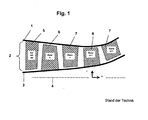
- the Fig.1 shows a schematic representation of a turbomachine as an example of a compressor consisting of an annular channel 1, the inside by a hub contour (rotor drum / hub 3) and the outside by a housing contour (Housing 1) is limited, and is equipped with a number of rotor blade rows and Statorschaufelschschsch within the annular channel 2 (rotor blades 6 and stator blades 7). There are blur-free spaces between the rows of blades.
- the turbomachine is flown from the left.
- the introduction of fluid by means of one or more suitable injectors is advantageous.
- special injection nozzles on the stator in particular special non-protruding injector nozzles, see Fig.2 , proposed.
- Injector nozzles according to the prior art and in particular include non-projecting nozzles, give rise to a noticeable disturbance of the approaching flow during operation and generate noticeable pressure losses already in the fluid jet generation. With the usual construction associated with the prior art, large parasitic leakage currents occur, which also adversely affect the flow in the turbomachine.
- the present invention has for its object to provide a fluid injector nozzle of the type mentioned, which achieves a very effective Grenz fürbeeinlung while avoiding the disadvantages of the prior art.
- the invention thus shows a fluid injector nozzle for use in turbomachines, wherein the nozzle channel of the injector is particularly streamlined and low-noise form.
- a fluid injector nozzle with a special arrangement has thus been created for use in turbomachines, which achieves a highly effective edge jet generation at the delimiting walls of the main flow path.
- the Fig. 2 shows an injector nozzle 8 according to the prior art.
- the upper small part of the figure shows a part of the flow path surface of a turbomachine.
- the section Z-Z is shown enlarged in the lower part of the picture. It shows the nature and arrangement of the injector nozzle 8.
- the injector nozzle 8 is designed so that it does not protrude into the flow path at any point. This causes significant flow field disturbances as soon as it is in operation and fluid flows from the injector nozzle 8 into the gas path of the turbomachine.
- a thick arrow indicates a main flow 9 in the turbomachine, the thin arrows indicate local flow processes.
- the strong curvatures of the nozzle contours also cause a poor guidance of the fluid on the way into the flow path of the turbomachine, even if the narrow section of the injector nozzle 8 is provided close to its outlet.
- the Fig. 3a shows four different embodiments or configurations of the fluid injector nozzle according to the invention 8.
- the parts a, b, c and d of Fig. 2 show a part of the flow path surface of a turbomachine.
- an injector nozzle 8 is provided, which according to the invention can extend over the entirety or a portion of the circumference of the flow path of the turbomachine.
- a thick arrow indicates the main flow 9 in the turbomachine, the thin arrows show the outflow of fluid from the injector nozzle 8.
- the injector nozzle 8 is designed such that it protrudes into the main flow path 9 of the turbomachine and in this way allows favorable guidance of the fluid before it enters the main flow path 9 and thus reduces disturbances in the injector fluid and main flow 9 Flow field occur.
- the injector nozzle 8 according to the invention can be provided directly in the main flow path wall or in a separate component which is inserted into the main flow path wall.
- the section ZZ according to Fig. 4 and 5 is shown enlarged. If the main flow path wall rolls as a flat surface in the plane of the drawing, the exit slot of the injector nozzle according to the invention is rectilinear or curved, possibly circular arc.
- the Fig. 3b shows a perspective view of two of the present invention possible shapes of the contour in the region of the nozzle exit.
- the projecting injector nozzle 8 has two side flanks oriented approximately with the main flow direction. In this case, no edges are provided downstream of the nozzle outlet opening.
- the figure part b. Shows an embodiment of the injector 8 with smooth outflowing in Hauptzuströmiques contours, ie, without directed into the main flow edges.
- a shoulder surface is provided only in the plane of the nozzle exit opening.
- the figure part c. Shows an embodiment of the injector nozzle 8 with smoothly outgoing contours in all directions, i.e., without edges directed into the main flow.
- two side edges are provided in the downstream and laterally of the nozzle outlet opening, which guide the exiting jet for a short distance.
- the Fig. 4 shows an inventive arrangement of the fluid injector in section ZZ in the meridian plane of the turbomachine, spanned by the axial coordinate x and the radial coordinate r.
- the injector fluid is supplied to the side of the main flow path 9, such that as far as possible tangentially directed along the main flow along the wall jet.
- the main flow 9 of the turbomachine is indicated by a large arrow. Given first is the contour of the main flow path GS, which is usually rotationally symmetrical to the axis (machine axis) of the turbomachine. In the region in which the injector nozzle 8 projects into the main flow path, this is shown as a dotted line.
- the injector nozzle 8 is supplied with fluid from a flow supply chamber 11 provided within the wall structure, see the thin arrow.
- the injector nozzle 8 is limited by the contours SG1 and SG2.
- a flow cross-sectional area which decreases continuously through the injector nozzle 8 and a round and edge-free shape of the inlet of the nozzle channel 10 are advantageous.
- the surfaces of the injector element and the main flow path wall wetted by the main flow adjoin one another.
- the contour of the injector is congruent with the contour of the main flow path wall at other circumferential positions.
- the last point in the flow direction of the nozzle contour SG1 is the nozzle end point C. If a vertical LS is established on the opposite nozzle contour SG2 and allowed to pass through the nozzle end point C, the base point D.sub.2 is SG2.
- the nozzle end point C and the foot point D define the outlet cross-section of the injector nozzle 8. According to the invention, the nozzle end point C is in the region of the main flow, that is, at a projecting beyond the main flow path contour GS part of the injector.
- the injector nozzle 8 projects particularly far when the base D assumes the position of the transition point E. If the injector nozzle 8 is provided in a separate component and a boundary point F exists, the transition point E may coincide with the boundary point F.
- the distance between the points E and F is at least three times the height of the nozzle end cross-section, namely the distance between the points C and D.
- Fig. 5 shows in much the same way as Fig. 4 an inventive arrangement of the fluid injector nozzle in section ZZ.
- the injector fluid is guided laterally to the main flow path, such that a jet directed as far as possible tangentially along the main flow wall arises.
- the injector nozzle 8 is supplied with fluid from a flow supply chamber SC provided within the bowl structure, see the thin arrow.
- the injector nozzle 8 is limited by the contours SG1 and SG2, and it may be advantageous, as shown in this example, to provide the narrowest point of the injector nozzle 8 not at the end cross-section, but at a position inside the injector nozzle 8, if the Flow rates in the injector 8 are high. In this case, with a perpendicular LS erected on the nozzle contour CG2, the points T and D which mark the narrowest cross section are obtained.
- the Fig. 6 shows an inventive arrangement of the fluid injector nozzle 8 in a curved section YY through the injector 8.
- this section it is inventively particularly advantageous to provide by the injector 8 a decreasing width of the nozzle channel and a round and edge-free shape of the inlet of the nozzle channel.
Landscapes
- Engineering & Computer Science (AREA)
- Mechanical Engineering (AREA)
- General Engineering & Computer Science (AREA)
- Physics & Mathematics (AREA)
- Fluid Mechanics (AREA)
- Jet Pumps And Other Pumps (AREA)
- Structures Of Non-Positive Displacement Pumps (AREA)
- Hydraulic Turbines (AREA)
- Nozzles (AREA)
Applications Claiming Priority (1)
| Application Number | Priority Date | Filing Date | Title |
|---|---|---|---|
| DE102008015207A DE102008015207A1 (de) | 2008-03-20 | 2008-03-20 | Fluid-Injektor-Düse |
Publications (3)
| Publication Number | Publication Date |
|---|---|
| EP2103811A2 true EP2103811A2 (fr) | 2009-09-23 |
| EP2103811A3 EP2103811A3 (fr) | 2012-07-11 |
| EP2103811B1 EP2103811B1 (fr) | 2013-11-06 |
Family
ID=40428189
Family Applications (1)
| Application Number | Title | Priority Date | Filing Date |
|---|---|---|---|
| EP09003020.6A Ceased EP2103811B1 (fr) | 2008-03-20 | 2009-03-03 | Buse d'injection de fluide |
Country Status (3)
| Country | Link |
|---|---|
| US (1) | US8152444B2 (fr) |
| EP (1) | EP2103811B1 (fr) |
| DE (1) | DE102008015207A1 (fr) |
Cited By (5)
| Publication number | Priority date | Publication date | Assignee | Title |
|---|---|---|---|---|
| EP2781692A1 (fr) * | 2013-03-20 | 2014-09-24 | Siemens Aktiengesellschaft | Diffuseur et turbomachine dotée du diffuseur |
| DE102015110250A1 (de) * | 2015-06-25 | 2016-12-29 | Rolls-Royce Deutschland Ltd & Co Kg | Statorvorrichtung für eine Strömungsmaschine mit einer Gehäuseeinrichtung und mehreren Leitschaufeln |
| DE102015110252A1 (de) * | 2015-06-25 | 2016-12-29 | Rolls-Royce Deutschland Ltd & Co Kg | Statorvorrichtung für eine Strömungsmaschine mit einer Gehäuseeinrichtung und mehreren Leitschaufeln |
| US10344616B2 (en) | 2015-06-25 | 2019-07-09 | Rolls-Royce Deutschland Ltd & Co Kg | Stator device for a continuous-flow machine with a housing appliance and multiple guide vanes |
| CN114688095A (zh) * | 2020-12-25 | 2022-07-01 | 上海连成(集团)有限公司 | 一种立式管道多级离心泵的径向转轴向末级导叶 |
Families Citing this family (12)
| Publication number | Priority date | Publication date | Assignee | Title |
|---|---|---|---|---|
| US9567942B1 (en) * | 2010-12-02 | 2017-02-14 | Concepts Nrec, Llc | Centrifugal turbomachines having extended performance ranges |
| DE102011107523B4 (de) * | 2011-07-15 | 2016-08-11 | MTU Aero Engines AG | System zum Einblasen eines Fluids, Verdichter sowie Turbomaschine |
| US11946379B2 (en) | 2021-12-22 | 2024-04-02 | Rolls-Royce North American Technologies Inc. | Turbine engine fan case with manifolded tip injection air recirculation passages |
| US11732612B2 (en) | 2021-12-22 | 2023-08-22 | Rolls-Royce North American Technologies Inc. | Turbine engine fan track liner with tip injection air recirculation passage |
| US11702945B2 (en) | 2021-12-22 | 2023-07-18 | Rolls-Royce North American Technologies Inc. | Turbine engine fan case with tip injection air recirculation passage |
| US12146413B1 (en) | 2023-12-12 | 2024-11-19 | Rolls-Royce North American Technologies Inc. | Circumferentially variable flow control in fan outlet guide vane assemblies for distortion management and stall margin in gas turbine engines |
| US12258870B1 (en) | 2024-03-08 | 2025-03-25 | Rolls-Royce North American Technologies Inc. | Adjustable fan track liner with slotted array active fan tip treatment for distortion tolerance |
| US12286936B1 (en) | 2024-05-09 | 2025-04-29 | Rolls-Royce North American Technologies Inc. | Adjustable fan track liner with groove array active fan tip treatment for distortion tolerance |
| US12215712B1 (en) | 2024-05-09 | 2025-02-04 | Rolls-Royce North American Technologies Inc. | Adjustable fan track liner with dual grooved array active fan tip treatment for distortion tolerance |
| US12209541B1 (en) | 2024-05-09 | 2025-01-28 | Rolls-Royce North American Technologies Inc. | Adjustable fan track liner with dual slotted array active fan tip treatment for distortion tolerance |
| US12168983B1 (en) | 2024-06-28 | 2024-12-17 | Rolls-Royce North American Technologies Inc. | Active fan tip treatment using rotating drum array in fan track liner with axial and circumferential channels for distortion tolerance |
| US12209502B1 (en) | 2024-06-28 | 2025-01-28 | Rolls-Royce North American Technologies Inc. | Active fan tip treatment using rotating drum array with axial channels in fan track liner for distortion tolerance |
Citations (2)
| Publication number | Priority date | Publication date | Assignee | Title |
|---|---|---|---|---|
| US5217348A (en) | 1992-09-24 | 1993-06-08 | United Technologies Corporation | Turbine vane assembly with integrally cast cooling fluid nozzle |
| DE102004030597A1 (de) | 2004-06-24 | 2006-01-26 | Rolls-Royce Deutschland Ltd & Co Kg | Strömungsarbeitsmaschine mit Aussenradstrahlerzeugung am Stator |
Family Cites Families (27)
| Publication number | Priority date | Publication date | Assignee | Title |
|---|---|---|---|---|
| NL95825C (fr) * | 1950-11-17 | |||
| US3238718A (en) * | 1964-01-30 | 1966-03-08 | Boeing Co | Gas turbine engine |
| US3685741A (en) * | 1970-07-16 | 1972-08-22 | Parker Hannifin Corp | Fuel injection nozzle |
| GB1386281A (en) * | 1972-03-06 | 1975-03-05 | Luft U Kaeltetechnik Veb K | Boundary layer control for turbo machines |
| DE2352236A1 (de) * | 1973-10-18 | 1975-04-30 | Graefer Albrecht Dipl Berging | Axialventilator |
| JPS5254809A (en) * | 1975-10-31 | 1977-05-04 | Hitachi Ltd | Axial-flow fluid machine construction |
| GB1550932A (en) * | 1976-04-15 | 1979-08-22 | Forster T O | Nozzle insert for a turbine |
| US4373325A (en) * | 1980-03-07 | 1983-02-15 | International Harvester Company | Combustors |
| FR2616889B1 (fr) * | 1987-06-18 | 1992-07-31 | Snecma | Carter de chambre de combustion de turboreacteur comportant des orifices de prelevement d'air |
| US5001895A (en) * | 1987-12-14 | 1991-03-26 | Sundstrand Corporation | Fuel injector for turbine engines |
| US4891936A (en) * | 1987-12-28 | 1990-01-09 | Sundstrand Corporation | Turbine combustor with tangential fuel injection and bender jets |
| US4989404A (en) * | 1988-12-12 | 1991-02-05 | Sundstrand Corporation | Turbine engine with high efficiency fuel atomization |
| US5205117A (en) * | 1989-12-21 | 1993-04-27 | Sundstrand Corporation | High altitude starting two-stage fuel injection |
| US5214911A (en) * | 1989-12-21 | 1993-06-01 | Sundstrand Corporation | Method and apparatus for high altitude starting of gas turbine engine |
| US5317864A (en) * | 1992-09-30 | 1994-06-07 | Sundstrand Corporation | Tangentially directed air assisted fuel injection and small annular combustors for turbines |
| EP0700498B1 (fr) | 1993-06-01 | 1998-10-21 | Pratt & Whitney Canada, Inc. | Injecteur radial de carburant, a entrainement d'air |
| SE9304194L (sv) | 1993-12-17 | 1995-06-18 | Abb Stal Ab | Bränslespridare |
| DE59710924D1 (de) * | 1997-09-15 | 2003-12-04 | Alstom Switzerland Ltd | Kühlvorrichtung für Gasturbinenkomponenten |
| US6071076A (en) * | 1997-12-16 | 2000-06-06 | General Electric Company | Actuation system for a gas turbine rotor blade |
| US6435816B1 (en) | 2000-11-03 | 2002-08-20 | General Electric Co. | Gas injector system and its fabrication |
| US7052231B2 (en) * | 2003-04-28 | 2006-05-30 | General Electric Company | Methods and apparatus for injecting fluids in gas turbine engines |
| DE10355241A1 (de) * | 2003-11-26 | 2005-06-30 | Rolls-Royce Deutschland Ltd & Co Kg | Strömungsarbeitsmaschine mit Fluidzufuhr |
| US7097414B2 (en) * | 2003-12-16 | 2006-08-29 | Pratt & Whitney Rocketdyne, Inc. | Inducer tip vortex suppressor |
| US7654088B2 (en) * | 2004-02-27 | 2010-02-02 | Pratt & Whitney Canada Corp. | Dual conduit fuel manifold for gas turbine engine |
| GB2413158B (en) * | 2004-04-13 | 2006-08-16 | Rolls Royce Plc | Flow control arrangement |
| DE102005015152A1 (de) | 2005-03-31 | 2006-10-05 | Alstom Technology Ltd. | Vormischbrenner für eine Gasturbinenbrennkammer |
| EP1710442A1 (fr) * | 2005-04-04 | 2006-10-11 | ABB Turbo Systems AG | Système de stabilisation de courant pour compresseur radial |
-
2008
- 2008-03-20 DE DE102008015207A patent/DE102008015207A1/de not_active Withdrawn
-
2009
- 2009-03-03 EP EP09003020.6A patent/EP2103811B1/fr not_active Ceased
- 2009-03-20 US US12/382,692 patent/US8152444B2/en active Active
Patent Citations (2)
| Publication number | Priority date | Publication date | Assignee | Title |
|---|---|---|---|---|
| US5217348A (en) | 1992-09-24 | 1993-06-08 | United Technologies Corporation | Turbine vane assembly with integrally cast cooling fluid nozzle |
| DE102004030597A1 (de) | 2004-06-24 | 2006-01-26 | Rolls-Royce Deutschland Ltd & Co Kg | Strömungsarbeitsmaschine mit Aussenradstrahlerzeugung am Stator |
Cited By (7)
| Publication number | Priority date | Publication date | Assignee | Title |
|---|---|---|---|---|
| EP2781692A1 (fr) * | 2013-03-20 | 2014-09-24 | Siemens Aktiengesellschaft | Diffuseur et turbomachine dotée du diffuseur |
| WO2014146858A1 (fr) * | 2013-03-20 | 2014-09-25 | Siemens Aktiengesellschaft | Diffuseur et turbomachine comportant le diffuseur |
| DE102015110250A1 (de) * | 2015-06-25 | 2016-12-29 | Rolls-Royce Deutschland Ltd & Co Kg | Statorvorrichtung für eine Strömungsmaschine mit einer Gehäuseeinrichtung und mehreren Leitschaufeln |
| DE102015110252A1 (de) * | 2015-06-25 | 2016-12-29 | Rolls-Royce Deutschland Ltd & Co Kg | Statorvorrichtung für eine Strömungsmaschine mit einer Gehäuseeinrichtung und mehreren Leitschaufeln |
| US10344616B2 (en) | 2015-06-25 | 2019-07-09 | Rolls-Royce Deutschland Ltd & Co Kg | Stator device for a continuous-flow machine with a housing appliance and multiple guide vanes |
| CN114688095A (zh) * | 2020-12-25 | 2022-07-01 | 上海连成(集团)有限公司 | 一种立式管道多级离心泵的径向转轴向末级导叶 |
| CN114688095B (zh) * | 2020-12-25 | 2024-05-14 | 上海连成(集团)有限公司 | 一种立式管道多级离心泵的径向转轴向末级导叶 |
Also Published As
| Publication number | Publication date |
|---|---|
| US20090238688A1 (en) | 2009-09-24 |
| US8152444B2 (en) | 2012-04-10 |
| DE102008015207A1 (de) | 2009-09-24 |
| EP2103811A3 (fr) | 2012-07-11 |
| EP2103811B1 (fr) | 2013-11-06 |
Similar Documents
| Publication | Publication Date | Title |
|---|---|---|
| EP2103811B1 (fr) | Buse d'injection de fluide | |
| EP2108784B1 (fr) | Turbomachine dotée d'un composant d'injecteur de fluide | |
| EP2194232B1 (fr) | Turbomachine dotée d'une barrière à couche frontière sur la paroi latérale | |
| DE69932688T2 (de) | Kühlungsöffnungen für Gasturbinenkomponenten | |
| EP2025945B1 (fr) | Machine de traitement des écoulements dotée d'un creux de paroi de canal de ceinture | |
| EP1609999B1 (fr) | Turbo machine | |
| EP2003292B1 (fr) | Machine de travail fluidique avec virole d'aube dotée d'un rebord | |
| EP1382855B1 (fr) | Turbomachine avec système de recirculation de fluide intégré | |
| EP2025946B1 (fr) | Bande de recouvrement dotée d'une production de rayons de blocage | |
| DE102007056953B4 (de) | Strömungsarbeitsmaschine mit Ringkanalwandausnehmung | |
| DE3530769C2 (de) | Schaufel für ein Gasturbinentriebwerk | |
| EP2226509B1 (fr) | Turbo compresseur ou pompe avec injection de fluide pour influencer la couche limite | |
| EP2009239A2 (fr) | Aube dotée d'une production de jets tangentiels sur le profil | |
| DE10355240A1 (de) | Strömungsarbeitsmaschine mit Fluidentnahme | |
| DE3534905A1 (de) | Hohle, durch ein stroemungsmittel gekuehlte turbinenschaufel | |
| EP2180193B1 (fr) | Turbomachine dotée d'un moyen pour énergiser des bords proches du côté aspirant | |
| EP1774179B1 (fr) | Aube de compresseur | |
| EP2499375A1 (fr) | Fond intermédiaire pour une turbomachine radiale | |
| EP3078804A1 (fr) | Agencement virole pour une rangée d'aubes de rotor ou stator et turbine associée | |
| EP2597257B1 (fr) | Aubage | |
| EP3473808A1 (fr) | Pale d'aube pour une aube mobile de turbine à refroidissement intérieur ainsi que procédé de fabrication d'une telle pale | |
| EP1723339A1 (fr) | Compresseur d'une turbine a gaz ainsi que turbine a gaz | |
| DE102020206365B4 (de) | Strömungsleitvorrichtung für eine Strömungsmaschine | |
| DE7907797U1 (de) | Axialverdichterschaufel fuer gasturbinentriebwerke mit einrichtungen zur grenzschichtbeeinflussung | |
| DE102023126341A1 (de) | Beschaufelung für eine Turbomaschine, sowie Turbomaschine |
Legal Events
| Date | Code | Title | Description |
|---|---|---|---|
| PUAI | Public reference made under article 153(3) epc to a published international application that has entered the european phase |
Free format text: ORIGINAL CODE: 0009012 |
|
| AK | Designated contracting states |
Kind code of ref document: A2 Designated state(s): AT BE BG CH CY CZ DE DK EE ES FI FR GB GR HR HU IE IS IT LI LT LU LV MC MK MT NL NO PL PT RO SE SI SK TR |
|
| AX | Request for extension of the european patent |
Extension state: AL BA RS |
|
| PUAL | Search report despatched |
Free format text: ORIGINAL CODE: 0009013 |
|
| AK | Designated contracting states |
Kind code of ref document: A3 Designated state(s): AT BE BG CH CY CZ DE DK EE ES FI FR GB GR HR HU IE IS IT LI LT LU LV MC MK MT NL NO PL PT RO SE SI SK TR |
|
| AX | Request for extension of the european patent |
Extension state: AL BA RS |
|
| RIC1 | Information provided on ipc code assigned before grant |
Ipc: F04D 29/68 20060101ALI20120607BHEP Ipc: F04D 29/16 20060101ALI20120607BHEP Ipc: F04D 27/02 20060101AFI20120607BHEP |
|
| 17P | Request for examination filed |
Effective date: 20120919 |
|
| AKX | Designation fees paid |
Designated state(s): DE FR GB |
|
| GRAP | Despatch of communication of intention to grant a patent |
Free format text: ORIGINAL CODE: EPIDOSNIGR1 |
|
| INTG | Intention to grant announced |
Effective date: 20130730 |
|
| GRAS | Grant fee paid |
Free format text: ORIGINAL CODE: EPIDOSNIGR3 |
|
| GRAA | (expected) grant |
Free format text: ORIGINAL CODE: 0009210 |
|
| AK | Designated contracting states |
Kind code of ref document: B1 Designated state(s): DE FR GB |
|
| REG | Reference to a national code |
Ref country code: GB Ref legal event code: FG4D Free format text: NOT ENGLISH |
|
| REG | Reference to a national code |
Ref country code: DE Ref legal event code: R096 Ref document number: 502009008264 Country of ref document: DE Effective date: 20140102 |
|
| REG | Reference to a national code |
Ref country code: DE Ref legal event code: R097 Ref document number: 502009008264 Country of ref document: DE |
|
| PLBE | No opposition filed within time limit |
Free format text: ORIGINAL CODE: 0009261 |
|
| STAA | Information on the status of an ep patent application or granted ep patent |
Free format text: STATUS: NO OPPOSITION FILED WITHIN TIME LIMIT |
|
| 26N | No opposition filed |
Effective date: 20140807 |
|
| REG | Reference to a national code |
Ref country code: DE Ref legal event code: R097 Ref document number: 502009008264 Country of ref document: DE Effective date: 20140807 |
|
| REG | Reference to a national code |
Ref country code: FR Ref legal event code: PLFP Year of fee payment: 8 |
|
| REG | Reference to a national code |
Ref country code: FR Ref legal event code: PLFP Year of fee payment: 9 |
|
| REG | Reference to a national code |
Ref country code: FR Ref legal event code: PLFP Year of fee payment: 10 |
|
| PGFP | Annual fee paid to national office [announced via postgrant information from national office to epo] |
Ref country code: GB Payment date: 20200327 Year of fee payment: 12 |
|
| GBPC | Gb: european patent ceased through non-payment of renewal fee |
Effective date: 20210303 |
|
| PG25 | Lapsed in a contracting state [announced via postgrant information from national office to epo] |
Ref country code: GB Free format text: LAPSE BECAUSE OF NON-PAYMENT OF DUE FEES Effective date: 20210303 |
|
| PGFP | Annual fee paid to national office [announced via postgrant information from national office to epo] |
Ref country code: FR Payment date: 20230323 Year of fee payment: 15 |
|
| PGFP | Annual fee paid to national office [announced via postgrant information from national office to epo] |
Ref country code: DE Payment date: 20230328 Year of fee payment: 15 |
|
| P01 | Opt-out of the competence of the unified patent court (upc) registered |
Effective date: 20230528 |
|
| REG | Reference to a national code |
Ref country code: DE Ref legal event code: R119 Ref document number: 502009008264 Country of ref document: DE |
|
| PG25 | Lapsed in a contracting state [announced via postgrant information from national office to epo] |
Ref country code: DE Free format text: LAPSE BECAUSE OF NON-PAYMENT OF DUE FEES Effective date: 20241001 |
|
| PG25 | Lapsed in a contracting state [announced via postgrant information from national office to epo] |
Ref country code: FR Free format text: LAPSE BECAUSE OF NON-PAYMENT OF DUE FEES Effective date: 20240331 |
|
| PG25 | Lapsed in a contracting state [announced via postgrant information from national office to epo] |
Ref country code: FR Free format text: LAPSE BECAUSE OF NON-PAYMENT OF DUE FEES Effective date: 20240331 Ref country code: DE Free format text: LAPSE BECAUSE OF NON-PAYMENT OF DUE FEES Effective date: 20241001 |