EP2103836A2 - Amortisseur d'oscillations doté d'une force d'amortissement à amplitude sélective - Google Patents
Amortisseur d'oscillations doté d'une force d'amortissement à amplitude sélective Download PDFInfo
- Publication number
- EP2103836A2 EP2103836A2 EP09154689A EP09154689A EP2103836A2 EP 2103836 A2 EP2103836 A2 EP 2103836A2 EP 09154689 A EP09154689 A EP 09154689A EP 09154689 A EP09154689 A EP 09154689A EP 2103836 A2 EP2103836 A2 EP 2103836A2
- Authority
- EP
- European Patent Office
- Prior art keywords
- piston rod
- valve
- vibration damper
- valve sleeve
- damper according
- Prior art date
- Legal status (The legal status is an assumption and is not a legal conclusion. Google has not performed a legal analysis and makes no representation as to the accuracy of the status listed.)
- Withdrawn
Links
- 238000013016 damping Methods 0.000 title claims description 26
- 239000012530 fluid Substances 0.000 claims description 7
- 230000007704 transition Effects 0.000 claims description 3
- 238000010276 construction Methods 0.000 description 2
- 230000004323 axial length Effects 0.000 description 1
- 230000000903 blocking effect Effects 0.000 description 1
- 230000001419 dependent effect Effects 0.000 description 1
- 230000004941 influx Effects 0.000 description 1
- 238000009434 installation Methods 0.000 description 1
- 230000003993 interaction Effects 0.000 description 1
- 239000000463 material Substances 0.000 description 1
- 230000001360 synchronised effect Effects 0.000 description 1
Images

Classifications
-
- F—MECHANICAL ENGINEERING; LIGHTING; HEATING; WEAPONS; BLASTING
- F16—ENGINEERING ELEMENTS AND UNITS; GENERAL MEASURES FOR PRODUCING AND MAINTAINING EFFECTIVE FUNCTIONING OF MACHINES OR INSTALLATIONS; THERMAL INSULATION IN GENERAL
- F16F—SPRINGS; SHOCK-ABSORBERS; MEANS FOR DAMPING VIBRATION
- F16F9/00—Springs, vibration-dampers, shock-absorbers, or similarly-constructed movement-dampers using a fluid or the equivalent as damping medium
- F16F9/32—Details
- F16F9/36—Special sealings, including sealings or guides for piston-rods
- F16F9/362—Combination of sealing and guide arrangements for piston rods
-
- F—MECHANICAL ENGINEERING; LIGHTING; HEATING; WEAPONS; BLASTING
- F16—ENGINEERING ELEMENTS AND UNITS; GENERAL MEASURES FOR PRODUCING AND MAINTAINING EFFECTIVE FUNCTIONING OF MACHINES OR INSTALLATIONS; THERMAL INSULATION IN GENERAL
- F16F—SPRINGS; SHOCK-ABSORBERS; MEANS FOR DAMPING VIBRATION
- F16F9/00—Springs, vibration-dampers, shock-absorbers, or similarly-constructed movement-dampers using a fluid or the equivalent as damping medium
- F16F9/32—Details
- F16F9/48—Arrangements for providing different damping effects at different parts of the stroke
Definitions
- the invention relates to a vibration damper with amplitude-selective damping force according to the preamble of patent claim 1.
- a hydraulic vibration damper with a piston rod which is guided axially movable together with a piston in a cylinder.
- the piston divides the cylinder into a piston rod side and a piston rod remote working space, both of which are filled with a damping medium.
- a valve ring is slidably disposed on the piston rod, which drives by its axial position a valve opening in its cross section.
- the valve ring is in contact with the piston rod via a seal.
- the valve ring performs an axial movement during a stroke movement of the piston rod.
- damping volume can flow out of the piston rod-side working space until the valve ring closes the valve opening after a defined stroke.
- the DE 39 14 298 C1 only describes one Principle solution that causes a Dämpfkrafter horrung only with a piston rod extension movement.
- the WO 2006/049 741 A1 relates to a vibration damper with amplitude-dependent damping force.
- an axially movable valve ring is guided, which is adjusted by means of friction contact to the inner wall of a cylinder in its position and thus controls a flow connection between two working spaces.
- the object of the present invention is to realize a vibration damper with amplitude-selective damping force both in a Kolbenstangeneinfahr- and a Kolbenstangenausfahrzi.
- this object is achieved in that the piston rod side working space a valve sleeve is arranged in which the valve ring is axially movable, which limits two working chambers within the valve sleeve, wherein the piston rod side working space and the piston rod remote working space each with a working chamber of the valve sleeve over at least one controlled via a check valve channel and the valve ring in each case controls a valve opening between a channel and a working chamber opening therein.
- the damping force is amplitude-selectively changed both in a retraction as well as an extension movement.
- the cylinder with an outer tubular body forms a fluid connection, which connects one of the working spaces with a working chamber in the valve sleeve.
- the fluid connection thus consists of very simple components and can absorb comparatively large volume flows.
- the channels are each assigned a bypass connection with a throttle device.
- the pressure in the work chamber associated with the working chamber of the valve sleeve is lowered via the throttle device to a desired level, so that the force acting on the valve body closing force is determined by the frictional force with the piston rod and the pressure in the valve sleeve.
- the bypass connection and the at least one channel are connected to each other via an anteroom, wherein between the antechamber and the bypass connection, the throttle device is arranged.
- the at least one channel and also the bypass connection are supplied with damping medium from a working space.
- the throttle device is driven by a friction-operated by the movement of the piston rod switching ring. Depending on the direction of movement of the piston rod and thus flow direction of the damping medium, the throttle device can be switched to a relatively unthrottled flow opening or to a throttle point.
- the antechamber in the outflow direction has a second throttle device to the adjacent working space.
- the channels are designed as a combined axial radial passages in the valve sleeve, wherein at a transition from a radial to an axial channel, the check valve is designed in the form of an elastic band.
- a section of the channel is formed by a lateral surface of the valve sleeve and a cylinder section enclosing the valve sleeve.
- valve sleeve is designed mirror-inverted relative to a transverse axis. There is no need to provide a special installation direction for the valve sleeve in the vibration damper.
- FIG. 1 shows a vibration damper 1 according to the construction principle of a two-pipe unit, the invention can also be used without restriction in another design.
- a piston rod 5 is arranged with a piston 7 axially movable.
- a bottom valve 9 limits the cylinder 3 end.
- a piston rod guide 11 serves as a closure.
- the cylinder completely filled with damping medium 3 in a piston rod side and a piston rod remote working space 13; 15 divided, damping valves 17; 19 executed in a known per se construction for both directions of movement of the piston rod 5.
- the cylinder comprises a first section 3a, whose inner wall serves as a slide for the piston 7 and a coupled via an adapter ring 21 second cylinder section 3b, in which a valve sleeve 23 is arranged, which serves to generate an amplitude-selective damping force of the vibration damper 1.
- the valve sleeve 23 is clamped axially between the adapter ring 21 and the piston rod guide 11.
- the fluid connection 29 is formed by the outer wall of the cylinder 3 and an outer tubular body 31. Concentric with the tube body 31 is still an outer container tube 33 is connected to a bottom 35 and the piston rod guide 11, wherein between the tube body 31 and the container tube 33 a filled only partially with damping medium Compensation space 37 extends, which is connected via the bottom valve 9 with the piston rod remote working space 15.
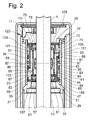
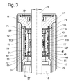
- the Figures 2 and 3 are limited in the synopsis to the second length section 3b of the cylinder, the two Figures 2 and 3 show different cutting plane.
- a valve ring 39 is arranged, which is in frictional contact with the piston rod 5.
- the valve ring 39 defines two working chambers 41; 43 within the valve sleeve 23.
- Between the adapter ring 21 and a lower shoulder 45 of the valve sleeve 23 are two valve disc pairs 47; 49 arranged at a distance from each other. These valve disk pairs form a first antechamber 51, in which a first switching ring 53 can perform an axial switching movement.
- a first piston rod 55 facing the piston rod side of the first pair of valve disks 47 has a closed annular surface which, together with the piston rod 5, forms an annular gap 57 with its inner diameter which permits an at least almost unthrottled inflow of damping medium into the first antechamber 51 in the opened operating state ,
- a Vorö Stammsventil isolation 59 is arranged in the direction of the valve sleeve 23.
- This Vorö Samuelsventilinflammatory 59 has in comparison to the first valve disc 55 has a much smaller inner diameter, so that only a minimum annular gap to the piston rod 5 is present.
- the second valve disc pair 49 is arranged in mirror image to the first switching ring 53, ie starting from the first vestibule 51, a second Vorö réelleside 63 with recess 65 and a superposed closed valve disc 67th
- the entire valve sleeve 23 is mirror images of their transverse axis 69 executed so that at an upper shoulder 71, a third valve disc pair 73 is separated by a second vestibule 75 of a fourth valve disc pair 77.
- a second switching ring 79 is disposed axially movable between the third 73 and the fourth pair of valve disks 77. Both switching rings 53; 75 are in frictional contact with the piston rod 5 and lead in the axial limits of the antechambers 51; 75 a synchronous movement with the piston rod movement.
- valve sleeve 23 Within the valve sleeve 23 is a respective working chamber 41; 43 via at least one via a check valve 81; 83 controlled channel 85; 87 with one of the working spaces 13; 15 connected in the cylinder 3.
- the working chamber 43 between the valve ring 39 and the piston rod guide 11 is connected via the second antechamber 75 and the gap 25 in the piston rod guide 11 and the fluid connection 29 to the piston rod remote working space 15.
- the working chamber 41 between the first antechamber 51 and the valve ring 39 is connected to the piston rod side working space 13.
- the channels 85; 87 are combined axial 89; 91; 93; 95 and radial channels 97; 99; 101; 103 executed in the valve sleeve 23.
- the radial channels 101; 103 each open with a valve opening 105; 107 in a working chamber 41; 43 and are controlled by the position of the valve ring 39 within the valve sleeve 23, that is opened or closed, wherein the position of the valve ring 23 in turn depends on the piston rod movement.
- a transverse channel 109; 111 at the first 67 and second vestibule 51; Attaches 75, the blind-hole-shaped axial passage 89 extends; 91, which radially outward another radial channel 97; 99 connects.
- Sections 93; 95 of the combined axial-radial passages 85; 87 are of lateral surfaces 113; 115 of the valve sleeve 23 and the valve sleeve 23 enclosing cylinder portion 3b formed.
- a check valve 81; 83 executed in the form of a radially elastic band.
- a ring seal 119 is chambered in a circumferential annular web 117, which in cooperation with the second longitudinal section 3b of the cylinder, the two channels 85; 87 in the area of the check valves 81; 83 separates from each other pressure-tight.
- the Figures 2 and 3 show the vibration damper 1 in a piston rod extension movement, is promoted in the damping chamber of the piston 7 from the piston rod-side working space 13 in the first vestibule 51.
- the first switching ring 53 abuts against the underside of the second pre-opening disc 63, so that only a small volume flow can flow into the lower working chamber 41.
- the Vorö Stammss 63 is by means of the recess 65 is a throttle device, so that when the Dämpfmediumübertritt from the first vestibule 51 in the lower working chamber 41, a pressure drop occurs.
- the flow path through the second Vorö Samuelside 63 provides a bypass connection to the channel 85 between the first vestibule 51 and the valve opening 105 in the upper working chamber 43.
- the check valve 97 is lifted from the lateral surface 113 of the valve sleeve 23 and the flow path to the upper working chamber 43 is released.
- the damping medium can flow from the piston rod side working chamber 13 and the upper working chamber 43 through a maximum open annular gap 121 of the third valve disc pair 101 in the second vestibule 75.
- the fourth valve disc pair 77 acts starting from the second vestibule 75 in the outflow direction to the adjacent working space 15, ie in this case the piston rod remote working space 15, as a throttle device, since the second switching ring 79 rests against a Vorö Stammsventilfit 123 with a recess 125.
- the pre-opening cross-section formed by the recess 125 determines the damping force of the vibration damper.
- This bypass volumetric flow does not significantly affect the damping force characteristic.
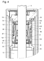
- the Fig. 4 shows an instantaneous position of the valve ring 39 and the shift rings 53; 79 at a piston rod retraction movement.
- damping medium from the piston 7 via the connection opening 27 in the first cylinder section 3a (FIG. Fig. 1 ) is displaced into the fluid connection 29, so that the damping medium via the gap 25 in the piston rod guide 11 flows through an open annular gap 131 of a fourth valve disc 133 in the second vestibule 75.
- the flow path through the combined axial and radial passages 85; 87 corresponds mutatis mutandis to the description of the Fig.
Landscapes
- Engineering & Computer Science (AREA)
- General Engineering & Computer Science (AREA)
- Mechanical Engineering (AREA)
- Fluid-Damping Devices (AREA)
Applications Claiming Priority (1)
| Application Number | Priority Date | Filing Date | Title |
|---|---|---|---|
| DE200810014543 DE102008014543B3 (de) | 2008-03-15 | 2008-03-15 | Schwingungsdämpfer mit amplitudenselektiver Dämpfkraft |
Publications (2)
| Publication Number | Publication Date |
|---|---|
| EP2103836A2 true EP2103836A2 (fr) | 2009-09-23 |
| EP2103836A3 EP2103836A3 (fr) | 2011-10-12 |
Family
ID=40690306
Family Applications (1)
| Application Number | Title | Priority Date | Filing Date |
|---|---|---|---|
| EP09154689A Withdrawn EP2103836A3 (fr) | 2008-03-15 | 2009-03-10 | Amortisseur d'oscillations doté d'une force d'amortissement à amplitude sélective |
Country Status (2)
| Country | Link |
|---|---|
| EP (1) | EP2103836A3 (fr) |
| DE (1) | DE102008014543B3 (fr) |
Cited By (2)
| Publication number | Priority date | Publication date | Assignee | Title |
|---|---|---|---|---|
| EP2388493A3 (fr) * | 2010-05-20 | 2015-03-11 | SUSPA GmbH | Amortisseur |
| CN114941680A (zh) * | 2021-02-16 | 2022-08-26 | Zf腓特烈斯哈芬股份公司 | 用于减振器的阻尼阀装置 |
Families Citing this family (3)
| Publication number | Priority date | Publication date | Assignee | Title |
|---|---|---|---|---|
| CN102032308A (zh) * | 2010-11-19 | 2011-04-27 | 重庆大学 | 可变阻尼减振器 |
| KR101771690B1 (ko) | 2013-05-14 | 2017-08-25 | 주식회사 만도 | 로드 가이드에 설치된 부가밸브를 갖는 감쇠력 가변식 쇽업소버 |
| DE102020209110A1 (de) * | 2020-07-21 | 2022-01-27 | Zf Friedrichshafen Ag | Dämpfventileinrichtung für einen Schwingungsdämpfer |
Citations (2)
| Publication number | Priority date | Publication date | Assignee | Title |
|---|---|---|---|---|
| DE3914298C1 (en) | 1989-04-29 | 1990-08-30 | Boge Ag, 5208 Eitorf, De | Hydraulic oscillation damper with fluid ram - has axially slidable control disc, guided sealingly on piston rod in ram cylinder |
| WO2006049741A1 (fr) | 2004-10-27 | 2006-05-11 | Tenneco Automotive Operating Company Inc. | Amortissement subordonne a la course |
Family Cites Families (5)
| Publication number | Priority date | Publication date | Assignee | Title |
|---|---|---|---|---|
| DE10300107B3 (de) * | 2003-01-07 | 2004-05-13 | Thyssenkrupp Bilstein Gmbh | Einrichtung für hydraulische Schwingungsdämpfer |
| US7216747B2 (en) * | 2004-10-14 | 2007-05-15 | Tenneco Automotive Operating Company Inc. | Amplitude controlled orifice valving |
| DE102005020293A1 (de) * | 2005-04-30 | 2006-11-09 | Zf Friedrichshafen Ag | Schwingungsdämpfer mit amplitudenselektiver Dämpfkraft |
| DE102006047093A1 (de) * | 2006-10-05 | 2008-04-10 | Zf Friedrichshafen Ag | Schwingungsdämpfer mit amplitudenselektiver Dämpfkraft |
| DE102006054257A1 (de) * | 2006-11-17 | 2008-05-29 | Zf Friedrichshafen Ag | Schwingungsdämpfer mit amplitudenabhängiger Dämpfkraft |
-
2008
- 2008-03-15 DE DE200810014543 patent/DE102008014543B3/de not_active Expired - Fee Related
-
2009
- 2009-03-10 EP EP09154689A patent/EP2103836A3/fr not_active Withdrawn
Patent Citations (2)
| Publication number | Priority date | Publication date | Assignee | Title |
|---|---|---|---|---|
| DE3914298C1 (en) | 1989-04-29 | 1990-08-30 | Boge Ag, 5208 Eitorf, De | Hydraulic oscillation damper with fluid ram - has axially slidable control disc, guided sealingly on piston rod in ram cylinder |
| WO2006049741A1 (fr) | 2004-10-27 | 2006-05-11 | Tenneco Automotive Operating Company Inc. | Amortissement subordonne a la course |
Cited By (3)
| Publication number | Priority date | Publication date | Assignee | Title |
|---|---|---|---|---|
| EP2388493A3 (fr) * | 2010-05-20 | 2015-03-11 | SUSPA GmbH | Amortisseur |
| US9109653B2 (en) | 2010-05-20 | 2015-08-18 | Suspa Gmbh | Damper |
| CN114941680A (zh) * | 2021-02-16 | 2022-08-26 | Zf腓特烈斯哈芬股份公司 | 用于减振器的阻尼阀装置 |
Also Published As
| Publication number | Publication date |
|---|---|
| DE102008014543B3 (de) | 2009-06-25 |
| EP2103836A3 (fr) | 2011-10-12 |
Similar Documents
| Publication | Publication Date | Title |
|---|---|---|
| DE1505478A1 (de) | Stufenlos verstellbarer Stossdaempfer,insbesondere fuer Kraftfahrzeuge | |
| EP1775495A2 (fr) | Amortisseur de vibrations avec force d'amortissement réglable | |
| EP1826454A2 (fr) | Amortisseur d'oscillations doté d'une force d'amortissement à amplitude sélective | |
| EP2366915A2 (fr) | Amortisseur d'oscillations doté d'une force d'amortissement en fonction de la levée | |
| DE10140580A1 (de) | Kolben-Zylinderaggregat mit einer geschwindigkeitsabhängigen Dämpfkraft | |
| DE102004058965B4 (de) | Schwingungsdämpfer mit amplitudenselektiver Dämpfkraft | |
| EP1923595B1 (fr) | Amortisseur d'oscillations doté d'une force d'amortissement dépendant de l'amplitude | |
| DE10058136C1 (de) | Umschaltventil mit strömungsrichtungsabhängigem Querschnitt | |
| DE102004030045B3 (de) | Ventilanordnung in einem Hydraulikkreis, Verwendung derselben und Anordnung zum Steuern eines hydraulischen Fahrzeugantriebs | |
| DE102008042103A1 (de) | Schwingungsdämpfer mit amplitudenselektiver Dämpfkraft | |
| WO2017198403A1 (fr) | Amortisseur de vibrations dont la force d'amortissement est fonction de la course | |
| EP2103836A2 (fr) | Amortisseur d'oscillations doté d'une force d'amortissement à amplitude sélective | |
| DE102005061164B4 (de) | Schwingungsdämpfer mit einer Anschlagfeder | |
| DE10260395B3 (de) | Schwingungsdämpfer mit verstellbarer Dämpfkraft | |
| WO2018103982A1 (fr) | Butée de fin de course pour amortisseur de vibrations | |
| DE102008043564A1 (de) | Schwingungsdämpfer mit einstellbarer Dämpfkraft | |
| DE102005045267B3 (de) | Schwingungsdämpfer mit amplitudenselektiver Dämpfkraft | |
| EP2003366A2 (fr) | Amortisseur de vibrations doté d'une valve d'amortissement réglable | |
| DE102008042637B4 (de) | Ventileinrichtung mit amplitudenabhängiger Dämpfkraft | |
| DE102010031144B4 (de) | Schwingungsdämpfer mit amplitudenabhängiger Dämpfkraft | |
| EP1795776B1 (fr) | Amortisseur de vibrations avec une force d'amortissement dépendant de l'amplitude | |
| EP2175160A2 (fr) | Amortisseur d'oscillations doté d'une force d'amortissement à amplitude sélective | |
| EP2128482B1 (fr) | Amortisseur d'oscillations doté d'une force d'amortissement dépendant de l'amplitude | |
| DE102008009543B3 (de) | Schwingungsdämpfer mit amplitudenabhängiger Dämpfkraft | |
| EP2058548A2 (fr) | Amortisseur d'oscillations doté d'une force d'amortissement à amplitude sélective |
Legal Events
| Date | Code | Title | Description |
|---|---|---|---|
| PUAI | Public reference made under article 153(3) epc to a published international application that has entered the european phase |
Free format text: ORIGINAL CODE: 0009012 |
|
| AK | Designated contracting states |
Kind code of ref document: A2 Designated state(s): AT BE BG CH CY CZ DE DK EE ES FI FR GB GR HR HU IE IS IT LI LT LU LV MC MK MT NL NO PL PT RO SE SI SK TR |
|
| AX | Request for extension of the european patent |
Extension state: AL BA RS |
|
| PUAL | Search report despatched |
Free format text: ORIGINAL CODE: 0009013 |
|
| AK | Designated contracting states |
Kind code of ref document: A3 Designated state(s): AT BE BG CH CY CZ DE DK EE ES FI FR GB GR HR HU IE IS IT LI LT LU LV MC MK MT NL NO PL PT RO SE SI SK TR |
|
| AX | Request for extension of the european patent |
Extension state: AL BA RS |
|
| RIC1 | Information provided on ipc code assigned before grant |
Ipc: F16F 9/36 20060101ALI20110908BHEP Ipc: F16F 9/50 20060101ALI20110908BHEP Ipc: F16F 9/48 20060101AFI20110908BHEP |
|
| 17P | Request for examination filed |
Effective date: 20120206 |
|
| AKX | Designation fees paid |
Designated state(s): AT BE BG CH CY CZ DE DK EE ES FI FR GB GR HR HU IE IS IT LI LT LU LV MC MK MT NL NO PL PT RO SE SI SK TR |
|
| STAA | Information on the status of an ep patent application or granted ep patent |
Free format text: STATUS: THE APPLICATION IS DEEMED TO BE WITHDRAWN |
|
| 18D | Application deemed to be withdrawn |
Effective date: 20131001 |