EP2103894B1 - Carabine à air comprimé et chargeur d'une carabine à air comprimé - Google Patents
Carabine à air comprimé et chargeur d'une carabine à air comprimé Download PDFInfo
- Publication number
- EP2103894B1 EP2103894B1 EP08017985A EP08017985A EP2103894B1 EP 2103894 B1 EP2103894 B1 EP 2103894B1 EP 08017985 A EP08017985 A EP 08017985A EP 08017985 A EP08017985 A EP 08017985A EP 2103894 B1 EP2103894 B1 EP 2103894B1
- Authority
- EP
- European Patent Office
- Prior art keywords
- gas
- air gun
- chamber
- discharge valve
- discharge
- Prior art date
- Legal status (The legal status is an assumption and is not a legal conclusion. Google has not performed a legal analysis and makes no representation as to the accuracy of the status listed.)
- Not-in-force
Links
Images










Classifications
-
- F—MECHANICAL ENGINEERING; LIGHTING; HEATING; WEAPONS; BLASTING
- F41—WEAPONS
- F41B—WEAPONS FOR PROJECTING MISSILES WITHOUT USE OF EXPLOSIVE OR COMBUSTIBLE PROPELLANT CHARGE; WEAPONS NOT OTHERWISE PROVIDED FOR
- F41B11/00—Compressed-gas guns, e.g. air guns; Steam guns
- F41B11/70—Details not provided for in F41B11/50 or F41B11/60
- F41B11/72—Valves; Arrangement of valves
- F41B11/724—Valves; Arrangement of valves for gas pressure reduction
Definitions
- the present invention relates to a magazine for an air gun and an air gun for firing bullets with compressed air as an energy source.
- An air gun for firing bullets using compressed air, and an air gun for carrying out both firing of bullets and blowback are known.
- a magazine capable of being fitted into these air guns is also known.
- a normal air gun as for example disclosed in document US 2006/0112944 A1 , is generally constructed to fire bullets utilizing ejection pressure of a gas canister fitted to a magazine. Gas that has been discharged from a gas canister passes through a discharge valve chamber, which is a space formed between a discharge valve and piercing assembly, due to the pressure of the gas, and a bullet positioned in a chamber is fired by opening the discharge valve (refer to related art 1, Fig. 26 ).
- the gas pressure discharged from the gas canister is high pressure (about 70 atmospheres) , there is a problem in that if that pressure is used directly the bullet speed would be too fast. Therefore, by attaching a regulator or the like, which is a decompression device, between a piercing assembly for attaching the gas canister and the discharge valve, the gas pressure discharged from the gas canister is reduced, and the bullet speed is controlled to within a constant speed.
- a regulator for decompressing gas pressure from the gas canister is provided with a piston cylinder 101, as shown in related art 1 ( Fig. 26 ) and related art 2 ( Fig. 27 ), with a piston 100, that is provided with a piston spring 103 at an outer side and is internally provided with a gas discharge path 102, being capable of reciprocating inside this piston cylinder 101.
- the piston spring 103 constantly urges the piston upwards, so as to open a through passage 105 from the piercing assembly 104.
- discharge gas from the gas canister fills up the discharge valve chamber 109 and the vaporizing chamber 110 to become a fixed high pressure, and the piston 100 is moved downwards inside the piston cylinder 101 against the urging force of the piston spring 103.
- Discharge gas from the gas canister is stopped as a result of a through passage closing plate 108 closing off the through passage 105 as a result of this movement, and gas pressure of the discharge valve chamber and the vaporizing chamber does not rise any further and is held at a constant pressure that is decompressed.
- This decompressed gas pressure moves the discharge valve as a result of a hit pin being subjected to a trigger action, to open the gas discharge path of the discharge valve and perform firing.
- the regulator that is the decompression device, is constructed of a combination of various precision members such as the piston cylinder 101, which is a hollow cylinder, and the piston 100, that is provided with the piston spring 103 on an outer side and is provided with gas discharge path 102 inside, inside the piston cylinder, as shown in Fig. 26 and Fig. 27 , and it is also necessary to adjust the urging force of the piston spring 103 that is subjected to pressure from the vaporization chamber and the discharge valve chamber.
- various precision members such as the piston cylinder 101, which is a hollow cylinder
- the piston 100 that is provided with the piston spring 103 on an outer side and is provided with gas discharge path 102 inside, inside the piston cylinder, as shown in Fig. 26 and Fig. 27 , and it is also necessary to adjust the urging force of the piston spring 103 that is subjected to pressure from the vaporization chamber and the discharge valve chamber.
- the present invention by providing an extremely simple member such as a partition wall having a microscopic hole section, it is possible to reliably reduce the speed of a bullet to a fixed speed, even a complicated decompression device such as a regulator is not provided. As a result, manufacturing time for the air gun is shortened, it is possible to lower manufacturing cost, and there is the effect of improving the manufacturing efficiency.
- the air gun shown in Fig. 1 to Fig. 24 is an air gun for firing of a bullet W using compressed air, and carrying out blowback, and has a vaporization chamber 6.
- the air gun shown in Fig. 1 to Fig. 24 is an air gun for firing of a bullet W using compressed air, and carrying out blowback, and has a vaporization chamber 6.
- Fig. 1 to Fig. 25 as an embodiment of this invention, description will be given for an air gun constructed with a partition wall 1 and a discharge valve 2 etc. are provided in a magazine M, and with the magazine M capable of being fitted into an air gun body B.
- Description of the air gun of the drawings of the embodiment of the invention is given using an air gun provided with a fully automatic mechanism, but the same is also true for an air gun that has a semi-automatic mechanism using a sear structure.
- the description is also similar for an air gun having a structure provided with a partition wall 1 and discharge valve 2 etc. in the air gun body B.
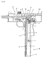
- Fig. 1 is a cross sectional explanatory drawing showing the whole of an air gun.
- the air gun of the embodiment of the invention comprises an air gun body B having parts such as a frame 10, handle grip section 10a, trigger 11, inner barrel 12, feed slope 13, chamber 14, bolt 15, bolt sear 16, bolt engagement protrusion 17, sear engagement section 18, hammer 19, hit pin 20, nozzle 21, nozzle cylinder 22, and a cylinder 23, and a magazine M capable of being fitted with a gas cylinder A from a gas cylinder insertion opening 8a which is a lower end opening section of the handle grip section 10a of the air gun body B.
- the magazine M has parts such as a partition wall 1, discharge valve 2, discharge valve chamber 3, change valve 4, change valve chamber 5, vaporization chamber 6, piercing assembly 7, gas canister housing chamber 8 and a loading section 9.
- compressed gas flows from the gas canister A through the piercing assembly 7 and vaporization chamber 6, through the microscopic hole 1b in the partition wall 1 and into the discharge valve 3.
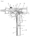
- Fig. 2 is a drawing showing the state where, from the state of Fig. 1 , the bolt handle 15b has been pulled fully to the rear of the air gun by hand.
- the bolt sear 16 is rotated upwards by the urging force of the bolt sear spring 16a, comes into contact with the trigger sear 11c and stops.
- a bolt 15 integral with the bolt handle 15b is urged towards the muzzle side of the air gun by a bolt return spring 15a, but the front end comes into contact with the bolt sear 16 and stops.
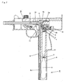
- Fig. 3 shows a state where a user has pulled the trigger 11. If the trigger 11 is pulled, the bolt sear 16 rotates downwards, and contact with the bolt 15 is released, and then the bolt 15 is advanced towards the air gun muzzle side by the bolt return spring 15a.
- Fig. 4 shows a state where the under nozzle protrusion 21a of the nozzle 21 starts to scoop out a bullet W as a result of the bolt 15 moving to the air gun muzzle side.
- a bullet W is placed in the chamber 14 from a bullet feed section 9a that opens at the uppermost part 9a of the loading section 9.
- Fig. 5 shows a state where the tip of the nozzle 21 has fed the bullet W to the chamber 14. Simultaneously, the hammer engagement protrusion 19a and the bolt engagement protrusion 17 make contact and are pressed to the muzzle side, thus moving the hammer 19 to the muzzle side also.
- Fig. 6 shows a state where the hit pin 20 is pressed to the muzzle side by movement of the hammer 19 to the muzzle side, and the discharge valve 2 has been pressed by this movement of the hit pin 20.
- the gas discharge path 2a is opened by the movement of the discharge valve 2 to the muzzle side.
- Fig. 7 shows a state where gas pressure from the opening of the gas discharge path 2a of Fig. 6 is discharged from the discharge valve chamber 3 to the change valve chamber 5 through the gas discharge path 2a of the discharge valve 2, and a bullet W is fired through the chamber 14 by gas pressure passing through the change valve firing side passage 4b of the change valve 4.
- the change valve 4 is normally urged towards the rear of the gun by the change valve spring 4a, so the change valve firing side passage 4b is open, and the change valve blowback side passage 4c is closed.
- the change valve firing side passage 4b becomes negative pressure, and as a result of that the change valve 4 moves to the muzzle side against the urging force of the change valve spring 4a, to close the change valve firing side passage 4b and open the change valve blowback side passage 4c.
- the bolt 15 starts to retract to the rear due to the gas pressure that has passed through the change valve blowback side passage 4c.
- Fig. 9 shows a state where the hammer return spring 19b acts due to retraction of the bolt 15 to move the hammer 19 back. Due to retraction of the hammer 19, the hit pin 20 that was pressed to the muzzle side also retracts. The nozzle cylinder 22 is still stopped, and gas continues to enter the hollow C.
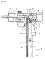
- Fig. 10 shows a state where the discharge valve 2 is moved backwards by the urging force of the discharge valve spring 2c, due to retraction of the hit pin 20, to close off the gas discharge path 2a. Because of the closing of the gas discharge path 2a, gas is no longer supplied to the change valve chamber 5, which means that the change valve 4 is urged by the change valve spring 4a to the rear of the air gun, the change valve firing side passage 4b opens, and the change valve blowback side passage 4c is closed. In Fig. 10 , the bolt 15 continues to retract strongly.
- Fig. 11 shows a state where the bolt 15 has retracted to the rearmost section where movement is possible. If the user releases the trigger 11 in this state, the trigger is returned to the position shown in Fig 2 by the trigger spring 11b. If the user pulls the trigger 11 in this state, the states of Fig. 3 to Fig. 11 are sequentially repeated until there is no longer any gas in the gas canister A (full auto).
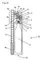
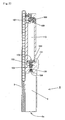
- Fig. 12 is a cross sectional explanatory drawing showing the whole of the magazine M
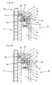
- Fig. 13 to Fig. 17 which are enlarged cross sectional explanatory drawings of essential parts showing operation of essential parts
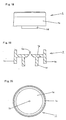
- Fig. 18 to Fig. 20 which showing a partition wall
- Fig. 21 to Fig. 23 showing a discharge valve
- Fig. 24 showing a discharge valve chamber.
- the magazine M has a loading section 9, capable of being loaded with bullets W and provided with a magazine spring 9c at a lower part and a bullet feed opening 9a at an upper part, a gas canister housing section 8 capable of holding a gas canister A, a piercing assembly 7 meshing with a gas exhaust nozzle of the gas canister A, a puncture section 7a at a peripheral part of the piercing assembly 7, a vaporization chamber 6, a partition wall 1 having a microscopic hole 1b, a filter 1e provided on a filter mounting section 1d so as to cover the microscopic hole 1b, a discharge valve 2 having a gas discharge path 2a, a discharge valve chamber 3, a change valve 4 and a change valve chamber 5.
- the partition wall 1 has a microscopic hole 1b formed in the center of a circular plate 1a, as shown in Fig. 18 to Fig. 20 , and is provided between the piercing assembly 7 and the discharge valve 2.
- the partition wall 1 is provided fitting into an inner wall of the vaporization chamber 6 using the peripheral wall 1c formed at the periphery of the circular plate 1a provided at an upper end section of the vaporization chamber 6.
- 1d is a filter mounting part, and is provided with a filter 1e, but it is also possible to not provide the filter 1e.
- the microscopic hole 1b of the partition wall 1 is formed having an opening area that is wide at the vaporization, chamber 6 side, which is upstream of the gas, and narrow at the discharge chamber 3 side, and is an inverted cone shape, for example, and with this embodiment the narrow surface area of the discharge chamber 3 side is 0.2 mm 2 or less.
- the discharge valve 2 is formed with a gas discharge path 2a passing though the inside, running longitudinally downwards from a mid point in the longitudinal direction, as shown in Fig. 21 to Fig. 23 .
- 2b is a valve large diameter section,
- Fig. 24 shows the discharge valve chamber 3, with a mesh pattern, in a state where the gas discharge path 2a of the discharge valve 2 is closed off.
- the discharge valve chamber 3 is a space formed between the partition wall 1, in a state where the discharge valve 2 is urged to the rear of the air gun by the urging force of the discharge valve spring 2c and the gas discharge path 2a is closed.
- the total volume of parts of the discharge valve chamber 3 shown by the mesh pattern is 580 mm 3 or less in this embodiment, but it can be 580 mm 3 or greater.
- FIG. 13 is a drawing corresponding to the state of the air gun that was described in Fig. 2 to Fig. 5 .
- the discharge valve 2 is urged to the rear of the air gun by the urging force of the discharge valve spring 2c, resulting in a state where the gas discharge path 2a is closed off.
- the gas discharge path 2a is closed off.
- Fig. 14 is a drawing corresponding to the state of the air gun that was described in Fig. 6 .
- the hit pin 20 is pressed to the muzzle side by movement of the hammer 19 to the muzzle side, and the discharge valve 2 is moved to the muzzle side by this movement of the hit pin 20.
- the gas discharge path 2a is opened by this movement of the discharge valve 2 to the muzzle side.
- the open area of this gas discharge path 2a is larger than the open area of the microscopic hole section 1b of the partition wall 1 (0.2 mm 2 ) , and in this embodiment is about 3.1 mm 2 . Accordingly, with this embodiment the opening area of the gas discharge path 2a is about sixteen times the opening area of the microscopic hole section 1b.
- Numerical values of the opening area of the gas discharge path 2a and the opening area of the microscopic hole section 1b vary depending on conditions such as the material of respective members of the air gun, blowback strength, range of firing speeds for bullets to be fired, etc., and so the above numerical values are examples. Accordingly, it is also possible for the opening area of the gas discharge path 2a to be larger than the opening area of the microscopic hole section 1b.
- Fig. 15 is a drawing corresponding to the state of the air gun that was described in Fig. 7 .
- compressed gas flows from the gas canister A through the piercing assembly 7 and the vaporization chamber 6, and from the microscopic hole section 1b of the partition wall 1 into the discharge valve chamber 3, and is discharged from the discharge valve chamber 3 through the opened gas discharge passage 2a to the change valve chamber 5. Further, compressed gas passes through the change valve firing side passage 4b of the change valve 4 provided in the change valve chamber 5, and fires a bullet that is in the chamber 14.
- a volume of compressed gas per unit time that flows into the discharge valve chamber 3 from the microscopic hole section 1b of the partition wall 1 is smaller than the gas volume per unit time that flows out from the discharge valve chamber 3 to the change valve chamber due to the opening of the gas discharge path 2a of the discharge valve 2, because the opening area of the microscopic hole section 1b is smaller that the opening area of the gas discharge path 2a. Accordingly, the gas pressure of the discharge valve chamber 5 is lower than the gas pressure of the vaporization chamber 6.
- Fig. 16 is a drawing corresponding to the state of the air gun that was described in Fig. 9 .
- the hit pin 20 is also retracted.
- Fig. 17 is a drawing corresponding to the state of the air gun that was described in Fig. 10 and Fig. 11 .
- the discharge valve 2 is moved backwards by the urging force of the discharge valve spring 2c, due to retraction of the hit pin 20, to close off the gas discharge path 2a. Because of the closing of the gas discharge path 2a, gas is no longer supplied to the change valve chamber 5, which means that the change valve 4 is urged by the change valve spring 4a to the rear of the air gun, the change valve firing side passage 4b opens, and the change valve blowback side passage 4c is closed.
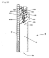
- Fig. 25 shows a magazine M of a style loaded with comparatively few bullets W in a loading section 9, and apart from the fact that the vaporization chamber 6 is not provided has similar structure and operation as the above-described magazine M.
- This invention is used in an air gun for performing firing of bullets using compressed gas, and in an air gun that performs firing of bullets and blowback using compressed gas, and can reduce the firing speed of a bullet with a simple structure.
Landscapes
- Engineering & Computer Science (AREA)
- General Engineering & Computer Science (AREA)
- Toys (AREA)
Claims (4)
- Chargeur (M) d'une carabine à air comprimé capable d'être ajusté dans une carabine à air comprimé pour tirer des balles (W) à l'aide de gaz comprimé, le chargeur (M) comprenant :un ensemble de perçage (7) sur lequel peut être adaptée une cartouche de gaz (A) en tant que source de gaz comprimé et dans lequel circule le gaz comprimé déchargé de la cartouche de gaz (A) ;une chambre (5) située à mi-distance de la trajectoire d'écoulement gazeux ;un clapet de décharge (2) situé entre l'ensemble de perçage (7) et la chambre (5) dans la trajectoire d'écoulement gazeux, le clapet de décharge (2) étant librement mobile entre une première position pour ouvrir une trajectoire de décharge de gaz (2a) et une seconde position pour fermer la trajectoire de décharge de gaz (2a), et étant capable de décharger le gaz comprimé de la cartouche de gaz (A) vers la chambre (5) ou d'interrompre la décharge de gaz comprimé provenant de la cartouche de gaz (A), dans lequel le gaz comprimé peut être déchargé depuis la trajectoire de décharge de gaz (2a) en ouvrant la trajectoire de décharge de gaz (2a) à l'aide de la force de pression exercée par une tige de percussion (20) de la carabine à air comprimé ;une chambre de clapet de décharge (3) formée entre une cloison (1) et le clapet de décharge (2) ;la cloison (1) ayant une section d'orifice microscopique (1b) située entre l'ensemble de perçage (7) et le clapet de décharge (2) dans la trajectoire d'écoulement gazeux ; etune région d'ouverture de la section d'orifice microscopique (1b) de la cloison (1) est inférieure à une région d'ouverture de la trajectoire de décharge de gaz (2a)fournissantun volume de gaz par temps unitaire, qui circule dans la chambre de clapet de décharge (3) depuis la face de cartouche de gaz (A) au moyen de la section d'orifice microscopique (1b), inférieur au volume de gaz par temps unitaire qui s'échappe de la chambre de clapet de décharge (3) résultant de l'ouverture de la trajectoire de décharge de gaz (2a) du clapet de décharge (2)et réduisant de façon fiable la vitesse d'une balle (W) à une vitesse fixe sans fournir d'autre dispositif de décompression.
- Chargeur (M) selon la revendication 1, comprenant en outre :une chambre de vaporisation (6) formée entre la cloison (1) et l'ensemble de perçage (7).
- Chargeur (M) selon la revendication 2, dans lequel
la section d'orifice microscopique (1b) de la cloison (1) présente une région d'ouverture qui est plus large sur la face de la chambre de vaporisation (6) que sur la face de la chambre de décharge. - Carabine à air comprimé pour tirer des balles à l'aide de gaz comprimé, comprenant :un chargeur (M) selon l'une quelconque des revendications 1 à 3,une détente (11) ;un marteau (19), qui est muni d'une tige de percussion (20) fixée à celui-ci, et lorsque la détente (11) est tirée, se déplace pour laisser la tige de percussion entrer en collision avec le clapet de décharge (2) pour ouvrir la trajectoire de décharge de gaz (2a), déchargeant ainsi le gaz comprimé à travers la trajectoire de décharge de gaz (2a).
Applications Claiming Priority (1)
| Application Number | Priority Date | Filing Date | Title |
|---|---|---|---|
| JP2008074113 | 2008-03-21 |
Publications (2)
| Publication Number | Publication Date |
|---|---|
| EP2103894A1 EP2103894A1 (fr) | 2009-09-23 |
| EP2103894B1 true EP2103894B1 (fr) | 2012-06-20 |
Family
ID=40227487
Family Applications (1)
| Application Number | Title | Priority Date | Filing Date |
|---|---|---|---|
| EP08017985A Not-in-force EP2103894B1 (fr) | 2008-03-21 | 2008-10-14 | Carabine à air comprimé et chargeur d'une carabine à air comprimé |
Country Status (3)
| Country | Link |
|---|---|
| US (1) | US8127755B2 (fr) |
| EP (1) | EP2103894B1 (fr) |
| TW (1) | TW200940942A (fr) |
Families Citing this family (14)
| Publication number | Priority date | Publication date | Assignee | Title |
|---|---|---|---|---|
| TW200909766A (en) * | 2007-08-28 | 2009-03-01 | Maruzen Co Ltd | Magazine ejector structure for air gun |
| US20100154763A1 (en) * | 2008-12-23 | 2010-06-24 | Tzu-Hsien Su | Structure improvement of trigger safety of toy gun |
| EP2434970B1 (fr) | 2009-05-26 | 2016-11-30 | Zimmer, Inc. | Outil à main destiné à enfoncer un clou à os dans un os fracturé |
| US7861702B1 (en) * | 2009-08-13 | 2011-01-04 | Yat Ming Sze | Gas air operated with draw back boring toy long-barrelled gun |
| CN102384699B (zh) * | 2010-08-30 | 2013-08-21 | 奕凯企业股份有限公司 | 气动玩具枪的弹匣装置 |
| US9987067B2 (en) * | 2012-07-11 | 2018-06-05 | Zimmer, Inc. | Bone fixation tool |
| US9615816B2 (en) * | 2013-03-15 | 2017-04-11 | Vidacare LLC | Drivers and drive systems |
| CA2944654C (fr) | 2014-04-03 | 2020-07-14 | Zimmer, Inc. | Outil orthopedique de fixation osseuse |
| WO2015198394A1 (fr) * | 2014-06-24 | 2015-12-30 | 株式会社東京マルイ | Dispositif de limitation de puissance pour pistolet d'imitation |
| EP3163246B1 (fr) * | 2014-06-24 | 2020-07-15 | Tokyo Marui Co., Ltd. | Dispositif de limitation de puissance pour un pistolet factice |
| US9631890B2 (en) * | 2015-06-28 | 2017-04-25 | Jui-Fu Tseng | Air canister for airsoft gun |
| US10966704B2 (en) | 2016-11-09 | 2021-04-06 | Biomet Sports Medicine, Llc | Methods and systems for stitching soft tissue to bone |
| US10619968B2 (en) * | 2018-01-31 | 2020-04-14 | Joshua Culiat | Pellet gun conversion adapter |
| US11378352B1 (en) * | 2021-01-19 | 2022-07-05 | Crosman Corporation | Gas powered semi-automatic airgun action |
Citations (1)
| Publication number | Priority date | Publication date | Assignee | Title |
|---|---|---|---|---|
| DE202007007490U1 (de) * | 2007-05-25 | 2007-09-20 | Liao, Jhih-Wun | Kugelmagazin für Spielzeug-Luftgewehre |
Family Cites Families (6)
| Publication number | Priority date | Publication date | Assignee | Title |
|---|---|---|---|---|
| EP0932013A3 (fr) * | 1998-01-22 | 2000-11-15 | Camilleri, Luciano Joseph | Cartouche de gaz et arme à gaz comprimé |
| US7237543B2 (en) | 2004-12-01 | 2007-07-03 | Yueh-Mei Chen | Gas magazine of a toy gun |
| US7353815B2 (en) * | 2005-03-14 | 2008-04-08 | Wilson Wei | Cartridge magazine assembly for air guns and paintball guns |
| US20060207584A1 (en) * | 2005-03-16 | 2006-09-21 | Ying-Hui Yeh | Gas decompression magazine of a toy gun |
| DE602006015212D1 (de) * | 2006-12-29 | 2010-08-12 | Maruzen Co Ltd | Druckluftwaffe |
| US7540280B2 (en) | 2007-05-24 | 2009-06-02 | Jhih-Wun Liao | Bullet cartridge for toy air gun |
-
2008
- 2008-05-08 TW TW097117001A patent/TW200940942A/zh not_active IP Right Cessation
- 2008-10-14 EP EP08017985A patent/EP2103894B1/fr not_active Not-in-force
- 2008-10-17 US US12/285,974 patent/US8127755B2/en not_active Expired - Fee Related
Patent Citations (1)
| Publication number | Priority date | Publication date | Assignee | Title |
|---|---|---|---|---|
| DE202007007490U1 (de) * | 2007-05-25 | 2007-09-20 | Liao, Jhih-Wun | Kugelmagazin für Spielzeug-Luftgewehre |
Also Published As
| Publication number | Publication date |
|---|---|
| TW200940942A (en) | 2009-10-01 |
| US20090235910A1 (en) | 2009-09-24 |
| TWI358521B (fr) | 2012-02-21 |
| US8127755B2 (en) | 2012-03-06 |
| EP2103894A1 (fr) | 2009-09-23 |
Similar Documents
| Publication | Publication Date | Title |
|---|---|---|
| US8127755B2 (en) | Air gun and magazine for air gun | |
| RU2333446C2 (ru) | Пневматический пистолет | |
| US7353816B2 (en) | Air gun | |
| JP4700123B2 (ja) | 電動エアガン | |
| US10415912B2 (en) | Bolt stop shock-absorption device in a gun | |
| CA2396031A1 (fr) | Pistolet pneumatique | |
| US10145647B2 (en) | Multi-bullet shooting electric gun | |
| DE19847638A1 (de) | Luftpistole | |
| CN101730830A (zh) | 自动手枪 | |
| US10458744B2 (en) | Shock-absorption device of piston mechanism in simulation gun | |
| TWI390173B (zh) | 玩具槍 | |
| US7967000B2 (en) | Low pressure paintball guns | |
| EP1729082B1 (fr) | Arme à gaz comprimé | |
| GB2426041A (en) | Gas operated gun mechanism | |
| JPH01285798A (ja) | ガス銃の弾丸発射装置 | |
| EP1939576B1 (fr) | Arme à air comprimé | |
| EP3601929B1 (fr) | Pistolet à boulettes de papier destiné à être utilisé avec des munitions en papier | |
| EP1677066B1 (fr) | Arme à air comprimé | |
| EP2607836B1 (fr) | Arme à gaz ou air précomprimé | |
| JP3169944B2 (ja) | ブローバック式ガスガンにおける弁装置 | |
| JPH08233491A (ja) | 玩具ガス銃 | |
| JP3511367B2 (ja) | 自動弾丸供給機構付玩具銃 | |
| JPH04327799A (ja) | 玩具銃における弾丸の発射装置 | |
| US10101113B2 (en) | Bullet supply port opening-closing device in simulation gun | |
| JPH0599594A (ja) | 玩具銃における弾丸の発射方法及びその装置 |
Legal Events
| Date | Code | Title | Description |
|---|---|---|---|
| PUAI | Public reference made under article 153(3) epc to a published international application that has entered the european phase |
Free format text: ORIGINAL CODE: 0009012 |
|
| AK | Designated contracting states |
Kind code of ref document: A1 Designated state(s): AT BE BG CH CY CZ DE DK EE ES FI FR GB GR HR HU IE IS IT LI LT LU LV MC MT NL NO PL PT RO SE SI SK TR |
|
| AX | Request for extension of the european patent |
Extension state: AL BA MK RS |
|
| 17P | Request for examination filed |
Effective date: 20091015 |
|
| 17Q | First examination report despatched |
Effective date: 20091124 |
|
| AKX | Designation fees paid |
Designated state(s): DE FR |
|
| GRAP | Despatch of communication of intention to grant a patent |
Free format text: ORIGINAL CODE: EPIDOSNIGR1 |
|
| GRAS | Grant fee paid |
Free format text: ORIGINAL CODE: EPIDOSNIGR3 |
|
| GRAA | (expected) grant |
Free format text: ORIGINAL CODE: 0009210 |
|
| AK | Designated contracting states |
Kind code of ref document: B1 Designated state(s): DE FR |
|
| REG | Reference to a national code |
Ref country code: DE Ref legal event code: R096 Ref document number: 602008016370 Country of ref document: DE Effective date: 20120816 |
|
| PLBE | No opposition filed within time limit |
Free format text: ORIGINAL CODE: 0009261 |
|
| STAA | Information on the status of an ep patent application or granted ep patent |
Free format text: STATUS: NO OPPOSITION FILED WITHIN TIME LIMIT |
|
| 26N | No opposition filed |
Effective date: 20130321 |
|
| REG | Reference to a national code |
Ref country code: DE Ref legal event code: R097 Ref document number: 602008016370 Country of ref document: DE Effective date: 20130321 |
|
| PGFP | Annual fee paid to national office [announced via postgrant information from national office to epo] |
Ref country code: DE Payment date: 20141029 Year of fee payment: 7 Ref country code: FR Payment date: 20141028 Year of fee payment: 7 |
|
| REG | Reference to a national code |
Ref country code: DE Ref legal event code: R119 Ref document number: 602008016370 Country of ref document: DE |
|
| PG25 | Lapsed in a contracting state [announced via postgrant information from national office to epo] |
Ref country code: DE Free format text: LAPSE BECAUSE OF NON-PAYMENT OF DUE FEES Effective date: 20160503 |
|
| REG | Reference to a national code |
Ref country code: FR Ref legal event code: ST Effective date: 20160630 |
|
| PG25 | Lapsed in a contracting state [announced via postgrant information from national office to epo] |
Ref country code: FR Free format text: LAPSE BECAUSE OF NON-PAYMENT OF DUE FEES Effective date: 20151102 |