EP2104017A2 - Ensemble de commutation rotatif pour climatiseur dans véhicule - Google Patents
Ensemble de commutation rotatif pour climatiseur dans véhicule Download PDFInfo
- Publication number
- EP2104017A2 EP2104017A2 EP09290184A EP09290184A EP2104017A2 EP 2104017 A2 EP2104017 A2 EP 2104017A2 EP 09290184 A EP09290184 A EP 09290184A EP 09290184 A EP09290184 A EP 09290184A EP 2104017 A2 EP2104017 A2 EP 2104017A2
- Authority
- EP
- European Patent Office
- Prior art keywords
- switch assembly
- cable
- holder
- knob
- housing
- Prior art date
- Legal status (The legal status is an assumption and is not a legal conclusion. Google has not performed a legal analysis and makes no representation as to the accuracy of the status listed.)
- Granted
Links
Images


Classifications
-
- G—PHYSICS
- G05—CONTROLLING; REGULATING
- G05G—CONTROL DEVICES OR SYSTEMS INSOFAR AS CHARACTERISED BY MECHANICAL FEATURES ONLY
- G05G1/00—Controlling members, e.g. knobs or handles; Assemblies or arrangements thereof; Indicating position of controlling members
- G05G1/08—Controlling members for hand actuation by rotary movement, e.g. hand wheels
- G05G1/10—Details, e.g. of discs, knobs, wheels or handles
-
- B—PERFORMING OPERATIONS; TRANSPORTING
- B60—VEHICLES IN GENERAL
- B60K—ARRANGEMENT OR MOUNTING OF PROPULSION UNITS OR OF TRANSMISSIONS IN VEHICLES; ARRANGEMENT OR MOUNTING OF PLURAL DIVERSE PRIME-MOVERS IN VEHICLES; AUXILIARY DRIVES FOR VEHICLES; INSTRUMENTATION OR DASHBOARDS FOR VEHICLES; ARRANGEMENTS IN CONNECTION WITH COOLING, AIR INTAKE, GAS EXHAUST OR FUEL SUPPLY OF PROPULSION UNITS IN VEHICLES
- B60K35/00—Instruments specially adapted for vehicles; Arrangement of instruments in or on vehicles
- B60K35/10—Input arrangements, i.e. from user to vehicle, associated with vehicle functions or specially adapted therefor
-
- B—PERFORMING OPERATIONS; TRANSPORTING
- B60—VEHICLES IN GENERAL
- B60K—ARRANGEMENT OR MOUNTING OF PROPULSION UNITS OR OF TRANSMISSIONS IN VEHICLES; ARRANGEMENT OR MOUNTING OF PLURAL DIVERSE PRIME-MOVERS IN VEHICLES; AUXILIARY DRIVES FOR VEHICLES; INSTRUMENTATION OR DASHBOARDS FOR VEHICLES; ARRANGEMENTS IN CONNECTION WITH COOLING, AIR INTAKE, GAS EXHAUST OR FUEL SUPPLY OF PROPULSION UNITS IN VEHICLES
- B60K35/00—Instruments specially adapted for vehicles; Arrangement of instruments in or on vehicles
- B60K35/20—Output arrangements, i.e. from vehicle to user, associated with vehicle functions or specially adapted therefor
- B60K35/25—Output arrangements, i.e. from vehicle to user, associated with vehicle functions or specially adapted therefor using haptic output
-
- G—PHYSICS
- G05—CONTROLLING; REGULATING
- G05G—CONTROL DEVICES OR SYSTEMS INSOFAR AS CHARACTERISED BY MECHANICAL FEATURES ONLY
- G05G5/00—Means for preventing, limiting or returning the movements of parts of a control mechanism, e.g. locking controlling member
- G05G5/03—Means for enhancing the operator's awareness of arrival of the controlling member at a command or datum position; Providing feel, e.g. means for creating a counterforce
-
- G—PHYSICS
- G05—CONTROLLING; REGULATING
- G05G—CONTROL DEVICES OR SYSTEMS INSOFAR AS CHARACTERISED BY MECHANICAL FEATURES ONLY
- G05G7/00—Manually-actuated control mechanisms provided with one single controlling member co-operating with one single controlled member; Details thereof
- G05G7/02—Manually-actuated control mechanisms provided with one single controlling member co-operating with one single controlled member; Details thereof characterised by special provisions for conveying or converting motion, or for acting at a distance
- G05G7/10—Manually-actuated control mechanisms provided with one single controlling member co-operating with one single controlled member; Details thereof characterised by special provisions for conveying or converting motion, or for acting at a distance specially adapted for remote control
-
- B—PERFORMING OPERATIONS; TRANSPORTING
- B60—VEHICLES IN GENERAL
- B60K—ARRANGEMENT OR MOUNTING OF PROPULSION UNITS OR OF TRANSMISSIONS IN VEHICLES; ARRANGEMENT OR MOUNTING OF PLURAL DIVERSE PRIME-MOVERS IN VEHICLES; AUXILIARY DRIVES FOR VEHICLES; INSTRUMENTATION OR DASHBOARDS FOR VEHICLES; ARRANGEMENTS IN CONNECTION WITH COOLING, AIR INTAKE, GAS EXHAUST OR FUEL SUPPLY OF PROPULSION UNITS IN VEHICLES
- B60K2360/00—Indexing scheme associated with groups B60K35/00 or B60K37/00 relating to details of instruments or dashboards
- B60K2360/126—Rotatable input devices for instruments
-
- Y—GENERAL TAGGING OF NEW TECHNOLOGICAL DEVELOPMENTS; GENERAL TAGGING OF CROSS-SECTIONAL TECHNOLOGIES SPANNING OVER SEVERAL SECTIONS OF THE IPC; TECHNICAL SUBJECTS COVERED BY FORMER USPC CROSS-REFERENCE ART COLLECTIONS [XRACs] AND DIGESTS
- Y10—TECHNICAL SUBJECTS COVERED BY FORMER USPC
- Y10T—TECHNICAL SUBJECTS COVERED BY FORMER US CLASSIFICATION
- Y10T74/00—Machine element or mechanism
- Y10T74/18—Mechanical movements
- Y10T74/18568—Reciprocating or oscillating to or from alternating rotary
- Y10T74/18832—Reciprocating or oscillating to or from alternating rotary including flexible drive connector [e.g., belt, chain, strand, etc.]
Definitions
- the present invention relates to a rotary switch assembly for an air conditioner in a vehicle, and more particularly, to a rotary switch assembly for an air conditioner in a vehicle, in which detent means is mounted on a holder joined to a front housing to mount a knob on the holder, so that a cable switch assembly for operating a cable to control the air conditioner can be used to various switches in common without regard to existence and nonexistence of a detent structure or positions of the detent structure and the rotary switch assembly can prevent a movement of the knob and effectively transfer a manipulation force of the knob to the cable switch assembly since the detent means is mounted on the holder adjacent to the knob.
- an air conditioner for vehicles is a car interior component, which is installed in the vehicle heat for the purpose of cooling the inside of the vehicle in the summer season or the winter season or removing frost from a windshield in rainy season or winter season to thereby secure a driver's front and rear visual field.
- an air conditioner typically includes an evaporator and a heater core together, so that it heats, cools or ventilates the inside of the vehicle through the steps of selectively introducing the inside air or the outside air to the air conditioner, heating or cooling the introduced air, and blowing the heated or cooled air to the inside of the vehicle through vents of an air-conditioning case.
- a mixed ratio of air passed the evaporator and air passed the heater core is controlled by a temperature-adjusting door, and air moving toward the vents is controlled in its discharge direction by mode doors respectively mounted on the vents.
- the air is controlled by a vent mode for discharging the air toward the upper part of a passenger's body, a foot mode for discharging the air toward the passenger's feet, a bi-level mode for simultaneously discharging the air toward the upper part of the passenger's feet and the passenger's feet, and a defrost mode for removing frost or steam from a vehicle window by discharging the air toward the vehicle window.
- a controller is mounted on a center fascia panel of the vehicle, and the controller includes various switches mounted on a housing fixed on the center fascia panel.
- the switches are divided into a button type switch for allowing the passenger to press a button according to a selected operation mode, a lever type switch, in which a lever is joined at a position corresponding to a selected operation mode, and a rotary type switch for allowing the passenger to select an operation mode according to an angle position of a rotatable knob.
- the button type switch controls a mode by regulating electric power supplied to the switch, and the rotary type switch is manufactured in such a way that the rotatable knob is assembled relative to a switch body, and in this instance, the rotary type switch can control the mode by corresponding the angle position of the knob with the operation mode of the switch body.
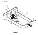
- the switch assembly 1 including the switches of various types has a structure that a plurality of the switches of different functions and structures are mounted on a housing 2. That is, an air volume switch 3 for adjusting a wind speed, a mode switch 4 for determining a discharge direction of air, a temperature-adjusting switch 5 for adjusting a wind temperature, and an air-conditioner switch (not shown) for turning on/off the air conditioner are mounted on one housing 2.
- the rotary type switches such as the temperature-adjusting switch 5 and the mode switch 4 are divided into cable type switches and electric switches according to their operation methods.
- the cable type switch will be described.
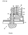
- the cable type rotary switch 10 generally includes: a gear shaft 20 having one end portion rotatably supported on a boss 12 formed on the inner bottom face of a housing 11; a gear lever 30 rotatably mounted on the circumference of the boss 12 in such a way as to be gear-coupled to the gear shaft 20, the gear lever 30 being connected with the temperature-adjusting door or a mode door of the air conditioner through a cable 40; and a knob 25 joined to an end portion of the gear shaft 20 protruding outwardly from the housing 11.
- the gear shaft 20 adopts a beveled tooth form and the gear lever 30 adopts an arced tooth form corresponding to the form of the gear shaft 20.
- knob 25 protrudes toward the front of the housing 11 in such a way as to allow a driver to rotate it.
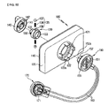
- U.S. Patent No. 5,235,866 discloses another example of the cable type rotary switch 50.
- the cable type rotary switch 50 includes: a control panel 51; a shaft 52 rotatably mounted on the control panel 51 and having a driving gear 53 formed on an outer circumferential face thereof; and a cable switch assembly 60 mounted behind the control panel 51 and connected with the driving gear 53 of the shaft 52 through a driven gear 62 formed at one side thereof in order to operate a pair of cables for controlling the air conditioner.
- the cable switch assembly 60 includes: a housing 65 joined behind the control panel 51; a pulley 61 rotatably mounted on the housing 65 and gear-coupled with the driving gear 52 of the shaft 52 through the driven gear 62 formed on one side thereof; and a pair of cables 55 having one side wound on the pulley 61 and the other side connected with the air conditioner to control the air conditioner.
- the pulley 61 of the cable switch assembly 60 connected with the driving gear 53 through the driven gear 62 is rotated.
- the pulley 61 is rotated in the forward direction or in the reverse direction, while the cables 55 are wound on or released from the pulley 61, the cam and the levers of the air conditioner connected with the other side of the cable 55 are rotated, and hence, the temperature-adjusting door and the mode doors interlocked with the cams and the levers are actuated.
- the cable switch assembly 60 for controlling the air conditioner by winding or releasing the cables 55 on or from the pulley can be designed freely since there is no restriction in route of the cable 55.
- the temperature-adjusting switch 5 and the mode switch 4 belong to the cable type rotary switch 50.
- the mode switch 4 has the detent structure constructed in the cable switch assembly 60 to provide a suspension sense every mode position when the shaft 52 is rotated.
- the detent structure of the cable switch assembly 60 includes a detent portion 63 formed on the outer circumferential face of the pulley 61; and a detent spring 66 mounted on the housing 65, on which the pulley 61 is mounted, the detent spring 66 giving the suspension sense while elastically touching the detent portion 63.
- the detent spring 66 is elastically caught to the detent portion 63 of the pulley 61 during the rotation of the pulley 61, and hence, the passenger can more conveniently and exactly change a mode since the passenger can feel the suspension sense every specific rotational position (position of each mode) when the shaft 52 is rotated.
- the conventional cable type rotary switch 50 has a problem in that it is impossible to use the cable switch assembly 60 to the temperature-adjusting switch 5 and the mode switch 4 in common since the detent structure is constructed inside the cable switch assembly 60.
- the detent structure is formed integrally with the pulley 61, it is difficult to use the cable switch assembly 60 in common according to existence and nonexistence of the detent structure or positions of the detent structure, and hence, it increases a manufacturing cost.
- the present invention has been made to solve the above-mentioned problems occurring in the prior arts, and it is an object of the present invention to provide a rotary switch assembly for an air conditioner in a vehicle, in which detent means is mounted on a holder joined to a front housing to mount a knob on the holder, so that a cable switch assembly for operating a cable to control the air conditioner can be used to various switches in common without regard to existence and nonexistence of a detent structure or positions of the detent structure and the rotary switch assembly can prevent a movement of the knob and effectively transfer a manipulation force of the knob to the cable switch assembly since the detent means is mounted on the holder adjacent to the knob.
- a rotary switch assembly for an air conditioner in a vehicle, which is mounted on housings of a center fascia panel of the vehicle to operate a cable controlling the air conditioner, characterized in that the rotary switch assembly includes: a holder rotatably mounted in a through hole formed on the housing in a back and forth direction; a knob located on a front face of the housing and joined with the holder; detent means mounted between the holder and the housing, the detent means providing a click feeling every specific rotational position when the knob is rotated; and a cable switch assembly detachably connected with the holder for operating the cable by receiving a manipulation force of the knob through the holder.
- a rotary switch assembly for an air conditioner in a vehicle including: housings coupled with each other; a plurality of holders spaced apart from one another at predetermined intervals and rotatably mounted in a plurality of through holes formed on the housing in a back and forth direction; a plurality of knobs located on a front face of the housing and joined with the plural holders; a plurality of detent means mounted between the plural holders and the housing, the detent means being in different forms to provide a click feeling every specific rotational position of the knobs when the plural knobs are rotated; and a plurality of cable switch assemblies of the same form being detachably connected with the plural holders, the plural cable switch assemblies receiving a manipulation force of the plural knobs through the holders to operate cables for controlling the air conditioner.
- the cable switch assembly for operating a cable to control the air conditioner can be used to various switches in common without regard to existence and nonexistence of the detent structure or positions of the detent structure, and hence, a manufacturing cost is reduced.
- the rotary switch assembly can prevent a movement of the knob, enhance a manipulation feeling, and effectively transfer a manipulation force of the knob to the cable switch assembly.
- the present invention can increase a sense of unity between the knob and the holder and prevent a torsion when the knob is rotated since a diameter of the holder supporting the knob is large.
- FIG. 1 is a perspective view showing a conventional switch assembly
- FIG. 2 is a perspective view showing a conventional cable type rotary switch
- FIGS 3a and 3b are perspective views showing another conventional cable type rotary switch
- FIG. 4 is a perspective view of a rotary switch assembly according to the present invention.
- FIG. 5 is an exploded perspective view of the rotary switch assembly according to the present invention.
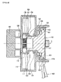
- FIG. 6 is a sectional view taken along the line of A-A of FIG. 4 ;
- FIG. 7 is a sectional view showing another example of detent means of FIG. 6 ;
- FIG. 8 is a sectional view showing a case where a knob and a holder of FIG. 6 are formed integrally with each other;
- FIG. 9 is an exploded perspective view showing a case where a cable switch assembly using a single cable is mounted on the rotary switch assembly according to the present invention.
- FIG. 4 is a perspective view of a rotary switch assembly according to the present invention
- FIG. 5 is an exploded perspective view of the rotary switch assembly
- FIG. 6 is a sectional view taken along the line of A-A of FIG. 4
- FIG. 7 is a sectional view showing another example of detent means of FIG. 6
- FIG. 8 is a sectional view showing a case where a knob and a holder of FIG. 6 are formed integrally with each other
- FIG. 9 is an exploded perspective view showing a case where a cable switch assembly using a single cable is mounted on the rotary switch assembly.
- the rotary switch assembly 100 for an air conditioner in a vehicle includes housings 110 and 120 mounted on a center fascia panel of the vehicle, a holder 130, a knob 140, detent means 135, and a cable switch assembly 150.
- the housings 110 and 120 are a front housing 110, on which the holder 130 is rotatably mounted, and a rear housing 120 joined to the front housing 110, and in this instance, the cable switch assembly 150 is detachably joined to the rear housing 120.
- the front housing 110 includes a through hole 111 formed therein in a back and forth direction in such a way that the holder 130 can be mounted thereon.
- the through hole 111 includes a stepped jaw portion 111a formed at one side thereof.
- housings 110 and 120 are separately manufactured into the front housing 110 and the rear housing 120 and assembled with each other in the present invention, but may be manufactured as a single housing.
- the holder 130 is rotatably inserted and joined into the through hole 111 of the front housing 110.
- the holder 130 includes a projection portion 131 formed on a front face thereof and a coupling recess portion 133 formed on a rear face thereof in such a way as to be coupled with the cable switch assembly 150.
- the projection portion 131 of the holder 130 projects to a predetermined length toward the front face of the front housing 110 to be coupled with the knob 140.
- the knob 140 is located on a front face of the front housing 110 and coupled with the holder 130 through coupling means 145.
- the coupling means 145 includes: the projection portion 131 formed on one of coupled faces of the holder 130 and the knob 140; and an insertion recess portion 141 formed on the other one of the coupled faces and coupled with the projection portion 131.
- the projection portion 131 is protrudingly formed on the front face of the holder 130 and includes a hook 132 protrudingly formed on an outer circumferential face thereof, which has at least one plane.
- the insertion recess portion 141 is formed on a rear face of the knob 140 in such a way as to correspond to the form of the outer circumferential face of the projection portion 131 and includes a recess 142 formed in such a way that the hook 132 is caught to the recess 142.
- a part of the projection portion 131 in the vicinity of the hook 132 is cut to thereby provide elasticity to the hook 132.
- two hooks 132 are formed, but the number of the hooks 132 can be changed freely.
- the outer circumferential face of the projection portion 131 of the holder 130 is in a polygonal form and the insertion recess portion 141 of the knob 140 is also in a polygonal form corresponding to the projection portion 131.
- the outer circumferential face of the projection portion 131 and the insertion recess portion 141 may be formed in a recess and protrusion shape (not shown).
- knob 140 and the holder 130 may be detachably coupled with each other through the coupling means 145, but may be formed integrally with each other as shown in FIG. 8 .
- the integrated knob 140 and holder 130 and the cable switch assembly 150 are assembled with each other in a state where the housings 110 and 120 are interposed therebetween, the structure and assembly of the present invention can be simplified.
- the integrated knob 140 and holder 130 can be simply assembled to the front face of the front housing 110, and the holder 130 of the knob 140 and a rotary shaft 152 of the cable switch assembly 150 are joined integrally and rotatably.
- the detent means 135 is mounted between the holder 130 and the front housing 110, and provides the suspension sense every specific rotation position when the knob 140 is rotated.
- the detent means 135 is not used in the temperature-adjusting switch, but is constructed in the mode switch to provide the suspension sense every air-conditioning mode when the knob 140 is rotated.
- the detent means 135 includes: a detent cap 137 elastically mounted in a receiving hole 136 of a predetermined depth, which is formed in the outer circumferential face of the holder 130, via an elastic member 138 interposed between the detent cap 137 and the receiving hole 136; and a retaining recess 112 formed on an inner circumferential face of the through hole 111 of the front housing 110 opposed to the detent cap 137 in such a way that the detent cap 137 is elastically caught thereto when the knob 140 is rotated.
- the receiving hole 136 and the detent cap 137 are formed by twos in the opposite directions relative to the holder 130, but may be formed only one by one.
- detent cap 137 and the elastic member 138 may be formed as separate members or as an integrated member.
- a plurality of the retaining recesses 112 are formed on the inner circumferential face of the through hole 111 of the front housing 110, and in this instance, the recesses 112 are formed at positions corresponding to the air-conditioning modes to change the air-conditioning mode of the air conditioner by rotating the knob 140.
- the detent cap 137 mounted on the holder 130 rotates along the inner circumferential face of the through hole 111 to provide the suspension sense every position where the detent cap 137 is elastically caught to the plural retaining recesses 112, so that the passenger can more conveniently and exactly change the air-conditioning mode.
- the temperature-adjusting switch does not need the detent means since it increases and decreases temperature by rotating the knob 140 in the forward direction or in the reverse direction.
- FIG. 7 illustrates another example of the detent means 135a.
- the detent means 135a includes: a detent cap 137a elastically mounted in a receiving hole 136a of a predetermined depth, which is formed in one side of the holder 130 facing the knob 140, via an elastic member 138a interposed between the detent cap 137a and the receiving hole 136a; and a retaining recess 112a formed on an inner surface of the front housing 110 opposed to the detent cap 137a in such a way that the detent cap 137 is elastically caught thereto when the knob 140 is rotated.
- the present invention since the present invention has the detent means 135 or 135a disposed between the holder 130 and the front housing 110, the detent structures of various forms as shown in FIGS. 6 and 7 can be constructed.
- the cable switch assembly 150 is detachably connected with the holder 130 and receives a manipulation force of the knob 140 through the holder 130 to thereby operate a cable 160 controlling the air conditioner.
- a single cable 160 or a pair of cables 160 may be used.
- the cable switch assembly 150 in case of a pair of cables 160, includes: a case 155 joined to a rear face of the rear housing 120; and a rotor 151 rotatably mounted inside the case 155 in such a way that end portions 161 of the cables 160 for controlling the air conditioner are wound on an outer circumferential face thereof in the opposite directions to each other, the rotor 151 having a rotor shaft 152 protrudingly formed on a front face thereof in such a way as to be detachably mounted on a rear face of the holder 130.
- the rotor 151 has a groove 153 formed on an outer circumferential face thereof, and the end portions 161 of the cables 160 inserted into the case 155 are fixed to the groove 153 in such a way as to be wound or released in the opposite directions to each other. That is, when the rotor 151 is rotated in one direction, while one of the cables 160 is gradually wound on the groove 153 of the rotor 151, the other of the cables 160 is gradually released from the groove 153 of the rotor 151.
- the cable switch assembly 150 includes: a case 155 joined to a rear face of the rear housing 120; and a rotor 151 rotatably mounted inside the case 155 in such a way that one end portion of the single cable 160a for controlling the air conditioner is wound on an outer circumferential face thereof, the rotor 151 having a rotor shaft 152 protrudingly formed on a front face thereof in such a way as to be detachably mounted on a rear face of the holder 130.
- the cable switch assemblies 150 and 170 are mounted on both end portions of the cable 160, wherein the cable switch assembly 150 mounted on one end portion of the cable 160 has the structure that the rotor shaft 152 is formed on the rotor 151 to be coupled with the holder 130 and the cable switch assembly 170 mounted on the other end portion of the cable 160 has a structure that a gear portion 171 is formed on one side of the rotor to actuate a cam (not shown) and levers (not shown), which are actuating means for actuating a temperature-adjusting door (not shown) or a mode door (not shown) of the air conditioner.
- the gear portion 171 of the rotor is mounted in such a way as to be gear-coupled with a gear portion (not shown) formed on the cam.
- the rotor 151 of the cable switch assembly 150 mounted on the one end portion of the cable 160 is rotated in the forward direction or in the reverse direction
- the rotor of the cable switch assembly 170 mounted on the other end portion of the cable 160 is also rotated in the forward direction or in the reverse direction.
- the rotor 151 of the cable switch assembly 150 mounted on the one end portion of the cable 160 transfers a manipulation force of the knob 140 to the one end portion of the cable 160 since it connects the holder 130 and the one end portion of the cable 160 with each other.
- the rotor of the cable switch assembly 170 mounted on the other end portion of the cable 160 transfers the manipulation force of the knob 140 transferred through the cable 160 to the actuating means of the air conditioner.
- the actuating means is the cam rotatably mounted on the outer face of the air conditioner to actuate the temperature-adjusting door or the mode doors mounted inside the air conditioner. That is, when the cam, which is the actuating means, engaging with the gear portion 171 of the rotor of the cable switch assembly 170 is rotated, the levers interlocked with the cam actuate the doors.
- the rear housing 120 includes a plurality of joining portions 122 for detachably joining the cable switch assembly 150. That is, the plural joining portions 122 are formed on the rear face of the rear housing 120 along the circumference of the case 155, and each of the joining portions 122 has a hook 122a protrudingly formed on an inner face thereof.
- the outer circumferential face of the case 155 is caught to the hook 122a of the joining portion 122 so that the case 155 is joined to the rear housing 120.
- the cable switch assembly 150 can be easily separated from the joining portion 122.
- the holder 130 or other structure may have a joining portion to support and fix the case 155.
- the joining portion 122 is provided to fix the case 155 to the rear face of the housing 1200, and in this instance, the rotor 155 is relatively rotatable.
- a projection portion 156 protrudingly formed on one side of the case 155 for rotatably supporting the rotor shaft 152 of the rotor 151 is forcedly fit to the through hole 121 of the rear housing 120.
- the rotor shaft 152 of the rotor 151 passes through the projection portion 156 of the case 155 and coupled to the rear face of the holder 130.
- one of the coupled faces of the rotor shaft 152 and the holder 130 has a portion 152a and the other one has a recessed portion 133 joined with the recess and protrusion portion 152a.
- the recess and protrusion portion 152a is formed on the outer circumferential face of the rotor shaft 152
- the recessed portion 133 is formed on the rear face of the holder 130, which is joined with the rotor shaft 152, in such a way as to be formed correspondingly to the outer circumferential face of the rotor shaft 152.
- the recessed portion 133 of the holder 130 and the outer circumferential face of the rotor shaft 152 may be formed not in the recess and protrusion form but in a polygonal form.
- the knob 140, the holder 130, and the cable switch assembly 150 are arranged on one rotary axis (C) and operated integrally. That is, the knob 140, the holder 130, and the cable switch assembly 150 are all arranged in concentric circles and directly connected with one another to be operated integrally.
- the holder 130 described above has various functions as follows.
- the holder 130 directly transfers the manipulation force of the knob 140 to the cable switch assembly 150, it is more simplified in structure than a gear, which indirectly transfers the manipulation force, and transfers the manipulation force more smoothly and securely.
- the holder 130 has the detent structure to provide the suspension sense (moderation feeling) when the knob 140 is rotated.
- the cable switch assembly 150 is modulated and detachably assembled to switches (temperature-adjusting switch, mode switch, and so on) without regard to existence and nonexistence of the detent portion or positions of the detent structure, so that the holder 130 can be used in common.
- the front housing 110 has a plurality of the through holes 111 spaced apart from one another at predetermined intervals, and a plurality of the holders 130 are rotatably mounted on the plural through holes 111.
- knobs 140 are joined to the plural holders 130 on the front face of the front housing 110.
- a plurality of the detent means 135 and 135a of different forms are respectively mounted between the plural holders 130 and the housing 110 in such a way as to provide the suspension sense at different rotational positions of the knobs 140 when the plural knobs 140 are rotated.
- the plural rotary switches performing different functions (temperature, air-conditioning mode, air volume, and so on) to control the air conditioner are mounted on the housings 110 and 120, since the plural rotary switches respectively perform different functions, the plural detent means 135 and 135a of different forms are mounted at the different rotational positions of the knobs 140 of the rotary switches.
- a plurality of the cable switch assemblies 150 of the same form are detachably connected and mounted to the plural holders 130.
- the plural detent means 135 and 135a are mounted on the plural rotary switches in different forms or omitted, the plural cable switch assemblies 150 can be used to the rotary switches in common since they are detachably assembled in the same form.
- the rotary switch assembly 100 in which the detent means 135 or 135a is mounted on the holder 130, is suitable to the mode switch, and can be used to the temperature-adjusting switch in a state where the detent means 135 mounted on the holder 130 is removed. Then, the cable switch assembly 150 detachably joined to the rear housing 120 and connected with the holder 130 can be used to different switches, such as the mode switch and the temperature-adjusting switch, in common without regard to existence and nonexistence of the detent structure and positions of the detent structure, and reduce the manufacturing cost.
- the detent means 135 or 135a since the detent means 135 or 135a is mounted on the holder 130 adjacent to the knob 140, the detent means 135 or 135a supports the holder 130 via elasticity of the elastic member 138 or 138a to thereby prevent a movement of the knob 140, enhance the manipulation feeling, and effectively transfer the manipulation force of the knob 140 to the cable switch assembly 150.
- a diameter of the holder 130 rotatably supporting the knob 140 is large, a sense of unity between the knob 140 and the holder 130 is increased, and hence, it can prevent a torsion when the knob 140 is rotated.
- the knob 140 can be easily assembled since the hook 132 of the projection portion 131 is caught to the recess 142 formed on the insertion recess portion 141.
- the cable switch assembly 150 can be also conveniently detachably assembled through the joining portions 122 formed on the rear face of the rear housing 120.
Landscapes
- Engineering & Computer Science (AREA)
- Physics & Mathematics (AREA)
- General Physics & Mathematics (AREA)
- Automation & Control Theory (AREA)
- Chemical & Material Sciences (AREA)
- Combustion & Propulsion (AREA)
- Transportation (AREA)
- Mechanical Engineering (AREA)
- Rotary Switch, Piano Key Switch, And Lever Switch (AREA)
- Air-Conditioning For Vehicles (AREA)
- Mechanical Control Devices (AREA)
Applications Claiming Priority (2)
| Application Number | Priority Date | Filing Date | Title |
|---|---|---|---|
| KR20080024431 | 2008-03-17 | ||
| KR1020090019098A KR101159138B1 (ko) | 2008-03-17 | 2009-03-06 | 차량 공조장치용 로터리 스위치 조립체 |
Publications (3)
| Publication Number | Publication Date |
|---|---|
| EP2104017A2 true EP2104017A2 (fr) | 2009-09-23 |
| EP2104017A3 EP2104017A3 (fr) | 2010-04-28 |
| EP2104017B1 EP2104017B1 (fr) | 2012-05-16 |
Family
ID=40673118
Family Applications (1)
| Application Number | Title | Priority Date | Filing Date |
|---|---|---|---|
| EP09290184A Ceased EP2104017B1 (fr) | 2008-03-17 | 2009-03-13 | Ensemble de commutation rotatif pour climatiseur dans véhicule |
Country Status (2)
| Country | Link |
|---|---|
| US (1) | US8173923B2 (fr) |
| EP (1) | EP2104017B1 (fr) |
Families Citing this family (5)
| Publication number | Priority date | Publication date | Assignee | Title |
|---|---|---|---|---|
| US8399788B2 (en) * | 2010-06-01 | 2013-03-19 | Tornatech Inc. | Mechanical activator for contactor |
| US9443677B2 (en) * | 2013-11-18 | 2016-09-13 | Motorola Solutions, Inc. | Flexible rotary control |
| US11220156B2 (en) * | 2017-09-25 | 2022-01-11 | Hanon Systems | Air conditioner for vehicle |
| EP3564794B1 (fr) * | 2018-05-03 | 2020-09-09 | Spotify AB | Ensemble de commande de lecture pour dispositif de lecture multimédia |
| TWM580255U (zh) * | 2019-01-25 | 2019-07-01 | 和碩聯合科技股份有限公司 | 旋鈕裝置 |
Citations (1)
| Publication number | Priority date | Publication date | Assignee | Title |
|---|---|---|---|---|
| US5235866A (en) | 1992-08-05 | 1993-08-17 | Handy And Harman Automotive Group, Inc. | Rotary temperature control device |
Family Cites Families (18)
| Publication number | Priority date | Publication date | Assignee | Title |
|---|---|---|---|---|
| JP2594937Y2 (ja) * | 1990-02-19 | 1999-05-24 | 株式会社 東海理化電機製作所 | ヒータコントロールユニット |
| US5218879A (en) * | 1991-09-30 | 1993-06-15 | Lake Center Industries, Inc. | Lost motion drive assembly |
| US5245886A (en) * | 1992-08-14 | 1993-09-21 | Delco Electronics Corporation | Rotary temperature mechanism |
| EP0669217B1 (fr) | 1994-02-24 | 1996-10-30 | Valeo Klimasysteme GmbH | Appareil de chauffage ou de climatisation pour véhicule automobile avec un appareil de commande |
| JPH08152932A (ja) | 1994-11-29 | 1996-06-11 | Karusonitsuku Tsuinteii Kk | ヒーターコントロールのクリック機構 |
| DE19517781C1 (de) | 1995-05-15 | 1996-09-12 | Daimler Benz Ag | Bedienelement |
| US5606893A (en) | 1995-05-15 | 1997-03-04 | Trw Inc. | Rolling detent mechanism |
| US5589671A (en) * | 1995-08-22 | 1996-12-31 | Us Controls Corp. | Rotary switch with spring stabilized contact control rotor |
| JP3454692B2 (ja) | 1997-04-25 | 2003-10-06 | 小島プレス工業株式会社 | ダイヤルシャフトの回転位置決め装置 |
| FR2786038B1 (fr) | 1998-11-13 | 2001-01-12 | Valeo Electronique | Dispositif de commande a boutons rotatifs coaxiaux pour un tableau de commande, en particulier de vehicule automobile |
| US6374696B1 (en) | 1999-12-17 | 2002-04-23 | Trw Inc. | Detent assembly |
| JP4005766B2 (ja) * | 2000-09-28 | 2007-11-14 | アルプス電気株式会社 | スイッチ装置 |
| JP2003016878A (ja) | 2001-04-27 | 2003-01-17 | Kojima Press Co Ltd | スイッチ構造 |
| US6578447B1 (en) * | 2002-03-11 | 2003-06-17 | The Boeing Company | Rotary indexing apparatus and related methods |
| JP4299089B2 (ja) * | 2003-09-24 | 2009-07-22 | 株式会社東海理化電機製作所 | 車両用空調装置の操作装置 |
| KR20060074028A (ko) | 2004-12-27 | 2006-07-03 | 한라공조주식회사 | 차량용 공조장치의 컨트롤커버와 하우징의 결합구조 |
| KR101151514B1 (ko) | 2005-05-04 | 2012-05-30 | 한라공조주식회사 | 차량 공조장치용 제어스위치 설치구조 |
| DE102008046097A1 (de) * | 2007-09-28 | 2009-04-16 | U-Shin Ltd. | Wählsteuervorrichtung |
-
2009
- 2009-03-12 US US12/402,546 patent/US8173923B2/en not_active Expired - Fee Related
- 2009-03-13 EP EP09290184A patent/EP2104017B1/fr not_active Ceased
Patent Citations (1)
| Publication number | Priority date | Publication date | Assignee | Title |
|---|---|---|---|---|
| US5235866A (en) | 1992-08-05 | 1993-08-17 | Handy And Harman Automotive Group, Inc. | Rotary temperature control device |
Also Published As
| Publication number | Publication date |
|---|---|
| EP2104017B1 (fr) | 2012-05-16 |
| US20090229387A1 (en) | 2009-09-17 |
| EP2104017A3 (fr) | 2010-04-28 |
| US8173923B2 (en) | 2012-05-08 |
Similar Documents
| Publication | Publication Date | Title |
|---|---|---|
| US20110107869A1 (en) | Integrated control apparatus for heating, ventilating, and air conditioning system for vehicle | |
| EP2104017B1 (fr) | Ensemble de commutation rotatif pour climatiseur dans véhicule | |
| CN101539325B (zh) | 用于车用空调器的旋转开关组件 | |
| EP2103459B1 (fr) | Appareil de connexion de câbles de commande pour climatiseur dans un véhicule | |
| KR20090068417A (ko) | 차량용 공기조화장치 | |
| KR20090099280A (ko) | 차량 공조장치용 컨트롤러의 케이블 연결장치 | |
| US9956852B2 (en) | Air vent apparatus for vehicle | |
| KR20100022763A (ko) | 차량 공조장치용 컨트롤러의 케이블 연결장치 | |
| KR101198742B1 (ko) | 차량 공조장치용 컨트롤러 | |
| KR101497336B1 (ko) | 차량용 공조 장치의 컨트롤 스위치 조립체 | |
| KR101820792B1 (ko) | 차량 공조장치용 컨트롤러 | |
| KR100727868B1 (ko) | 공조유니트의 도어 구동장치의 캠세팅 구조 | |
| JP4239433B2 (ja) | 車両用空調装置 | |
| KR101206965B1 (ko) | 차량 공조장치용 컨트롤러 | |
| KR101418853B1 (ko) | 차량 공조장치용 컨트롤러 | |
| KR100804662B1 (ko) | 차량 공조 스위치 | |
| KR101430009B1 (ko) | 차량 공조장치용 캠 및 구동유닛의 조립체 | |
| JP2009113545A (ja) | 車両の空調用操作装置 | |
| KR101445555B1 (ko) | 차량 공조장치용 캠 및 구동유닛의 조립체 | |
| JP2533263Y2 (ja) | 自動車用空調装置の配風ドア開閉レバー | |
| KR101220977B1 (ko) | 공조장치의 모드 스위치 조립체 | |
| KR20240137914A (ko) | 차량용 에어 벤트 | |
| KR20090099282A (ko) | 차량 공조장치용 컨트롤러의 케이블 연결장치 | |
| KR20220130441A (ko) | 차량용 내부 패널 조립체 및 그 조립방법 | |
| KR20040023374A (ko) | 자동차용 에어벤트 |
Legal Events
| Date | Code | Title | Description |
|---|---|---|---|
| PUAI | Public reference made under article 153(3) epc to a published international application that has entered the european phase |
Free format text: ORIGINAL CODE: 0009012 |
|
| AK | Designated contracting states |
Kind code of ref document: A2 Designated state(s): AT BE BG CH CY CZ DE DK EE ES FI FR GB GR HR HU IE IS IT LI LT LU LV MC MK MT NL NO PL PT RO SE SI SK TR |
|
| AX | Request for extension of the european patent |
Extension state: AL BA RS |
|
| PUAL | Search report despatched |
Free format text: ORIGINAL CODE: 0009013 |
|
| AK | Designated contracting states |
Kind code of ref document: A3 Designated state(s): AT BE BG CH CY CZ DE DK EE ES FI FR GB GR HR HU IE IS IT LI LT LU LV MC MK MT NL NO PL PT RO SE SI SK TR |
|
| AX | Request for extension of the european patent |
Extension state: AL BA RS |
|
| 17P | Request for examination filed |
Effective date: 20100618 |
|
| 17Q | First examination report despatched |
Effective date: 20100713 |
|
| AKX | Designation fees paid |
Designated state(s): DE FR |
|
| RIC1 | Information provided on ipc code assigned before grant |
Ipc: G05G 7/10 20060101ALI20110506BHEP Ipc: G05G 5/03 20080401ALI20110506BHEP Ipc: G05G 1/10 20060101AFI20110506BHEP |
|
| GRAP | Despatch of communication of intention to grant a patent |
Free format text: ORIGINAL CODE: EPIDOSNIGR1 |
|
| GRAS | Grant fee paid |
Free format text: ORIGINAL CODE: EPIDOSNIGR3 |
|
| GRAA | (expected) grant |
Free format text: ORIGINAL CODE: 0009210 |
|
| AK | Designated contracting states |
Kind code of ref document: B1 Designated state(s): DE FR |
|
| REG | Reference to a national code |
Ref country code: DE Ref legal event code: R096 Ref document number: 602009007012 Country of ref document: DE Effective date: 20120719 |
|
| PLBE | No opposition filed within time limit |
Free format text: ORIGINAL CODE: 0009261 |
|
| STAA | Information on the status of an ep patent application or granted ep patent |
Free format text: STATUS: NO OPPOSITION FILED WITHIN TIME LIMIT |
|
| 26N | No opposition filed |
Effective date: 20130219 |
|
| REG | Reference to a national code |
Ref country code: DE Ref legal event code: R097 Ref document number: 602009007012 Country of ref document: DE Effective date: 20130219 |
|
| REG | Reference to a national code |
Ref country code: DE Ref legal event code: R082 Ref document number: 602009007012 Country of ref document: DE Representative=s name: CABINET HIRSCH & ASSOCIES, FR |
|
| REG | Reference to a national code |
Ref country code: FR Ref legal event code: CD Owner name: HALLA VISTEON CLIMATE CONTROL CORPORATION Effective date: 20130827 |
|
| REG | Reference to a national code |
Ref country code: DE Ref legal event code: R081 Ref document number: 602009007012 Country of ref document: DE Owner name: HANON SYSTEMS, KR Free format text: FORMER OWNER: HALLA CLIMATE CONTROL CORP., DAEJEON, KR Effective date: 20130910 Ref country code: DE Ref legal event code: R081 Ref document number: 602009007012 Country of ref document: DE Owner name: HALLA VISTEON CLIMATE CONTROL CORP., KR Free format text: FORMER OWNER: HALLA CLIMATE CONTROL CORP., DAEJEON, KR Effective date: 20130910 Ref country code: DE Ref legal event code: R082 Ref document number: 602009007012 Country of ref document: DE Representative=s name: CABINET HIRSCH & ASSOCIES, FR Effective date: 20130910 |
|
| REG | Reference to a national code |
Ref country code: FR Ref legal event code: PLFP Year of fee payment: 8 |
|
| REG | Reference to a national code |
Ref country code: DE Ref legal event code: R082 Ref document number: 602009007012 Country of ref document: DE Representative=s name: CABINET HIRSCH & ASSOCIES, FR Ref country code: DE Ref legal event code: R081 Ref document number: 602009007012 Country of ref document: DE Owner name: HANON SYSTEMS, KR Free format text: FORMER OWNER: HALLA VISTEON CLIMATE CONTROL CORP., DAEJEON, KR |
|
| REG | Reference to a national code |
Ref country code: FR Ref legal event code: CD Owner name: HANON SYSTEMS Effective date: 20161212 |
|
| REG | Reference to a national code |
Ref country code: FR Ref legal event code: PLFP Year of fee payment: 9 |
|
| REG | Reference to a national code |
Ref country code: FR Ref legal event code: PLFP Year of fee payment: 10 |
|
| PGFP | Annual fee paid to national office [announced via postgrant information from national office to epo] |
Ref country code: DE Payment date: 20200303 Year of fee payment: 12 |
|
| PGFP | Annual fee paid to national office [announced via postgrant information from national office to epo] |
Ref country code: FR Payment date: 20210210 Year of fee payment: 13 |
|
| REG | Reference to a national code |
Ref country code: DE Ref legal event code: R119 Ref document number: 602009007012 Country of ref document: DE |
|
| PG25 | Lapsed in a contracting state [announced via postgrant information from national office to epo] |
Ref country code: DE Free format text: LAPSE BECAUSE OF NON-PAYMENT OF DUE FEES Effective date: 20211001 |
|
| PG25 | Lapsed in a contracting state [announced via postgrant information from national office to epo] |
Ref country code: FR Free format text: LAPSE BECAUSE OF NON-PAYMENT OF DUE FEES Effective date: 20220331 |