EP2104836B1 - Dispositif doté d'un capteur et de moyens de couplage - Google Patents
Dispositif doté d'un capteur et de moyens de couplage Download PDFInfo
- Publication number
- EP2104836B1 EP2104836B1 EP07819743.1A EP07819743A EP2104836B1 EP 2104836 B1 EP2104836 B1 EP 2104836B1 EP 07819743 A EP07819743 A EP 07819743A EP 2104836 B1 EP2104836 B1 EP 2104836B1
- Authority
- EP
- European Patent Office
- Prior art keywords
- sensor
- electrical
- conductor
- coupling
- copper
- Prior art date
- Legal status (The legal status is an assumption and is not a legal conclusion. Google has not performed a legal analysis and makes no representation as to the accuracy of the status listed.)
- Active
Links
Images


Classifications
-
- G—PHYSICS
- G01—MEASURING; TESTING
- G01D—MEASURING NOT SPECIALLY ADAPTED FOR A SPECIFIC VARIABLE; ARRANGEMENTS FOR MEASURING TWO OR MORE VARIABLES NOT COVERED IN A SINGLE OTHER SUBCLASS; TARIFF METERING APPARATUS; MEASURING OR TESTING NOT OTHERWISE PROVIDED FOR
- G01D11/00—Component parts of measuring arrangements not specially adapted for a specific variable
- G01D11/24—Housings ; Casings for instruments
- G01D11/245—Housings for sensors
-
- G—PHYSICS
- G01—MEASURING; TESTING
- G01P—MEASURING LINEAR OR ANGULAR SPEED, ACCELERATION, DECELERATION, OR SHOCK; INDICATING PRESENCE, ABSENCE, OR DIRECTION, OF MOVEMENT
- G01P1/00—Details of instruments
-
- G—PHYSICS
- G01—MEASURING; TESTING
- G01P—MEASURING LINEAR OR ANGULAR SPEED, ACCELERATION, DECELERATION, OR SHOCK; INDICATING PRESENCE, ABSENCE, OR DIRECTION, OF MOVEMENT
- G01P1/00—Details of instruments
- G01P1/02—Housings
- G01P1/026—Housings for speed measuring devices, e.g. pulse generator
-
- H—ELECTRICITY
- H01—ELECTRIC ELEMENTS
- H01B—CABLES; CONDUCTORS; INSULATORS; SELECTION OF MATERIALS FOR THEIR CONDUCTIVE, INSULATING OR DIELECTRIC PROPERTIES
- H01B7/00—Insulated conductors or cables characterised by their form
- H01B7/17—Protection against damage caused by external factors, e.g. sheaths or armouring
- H01B7/18—Protection against damage caused by wear, mechanical force or pressure; Sheaths; Armouring
Definitions
- the invention relates to a device with a sensor or actuator with coupling means for the electrical and mechanical contacting of the sensor or actuator.
- connection cable for a sensor with a conductor unit consisting of stainless steel wires and copper wires.
- a connection cable with a low electrical resistance and high flexibility, tensile strength and elasticity is obtained.
- the copper wires are preferably coated with an anti-oxidation layer.
- the connection cable may comprise hybrid wires which are stranded together and manufactured by integrally molding or forming stainless steel and copper.
- the connection cable is coated with an insulating sheath material such as Teflon resin.
- connection cable for a sensor is off DD 229 242 known.
- EP 0 571 129 A1 discloses a variable reluctance magnetic sensor having a coil comprising a barrel portion having a recess, a nominal front end, a front flange; a pole piece disposed in the recess; a magnet in the region of the pole piece; an electrical winding wound around the trumpet part and electrically connected to an output conductor to transmit an electrical signal to an output device; and an outer sleeve surrounding the coil, the magnet being fixed to the spool in front of the pole piece and the front flange, and the sleeve having an open end portion with an inner shoulder surface and a front portion having a front wall with an opening in the region of the magnet, for the magnet to protrude, an elastomeric front seal between the front flange and the front end portion being compressed to seal the electrical coil against medium flowing through the opening, and for covering the open rear end portion of the sleeve, a rear portion provided on a surface the rear end portion of the outer sleeve is welded
- EP 0 465 978 A1 discloses an electrical conductor wire for use in motor vehicles made by twisting a number of individual wires together, wherein the individual wires before twisting have a tensile strength of 80 to 160 kgf / mm 2 and a conductivity of 25 to 80% IACS and have a core comprising is made of steel containing 0.15 to 0.85% of carbon, the conductor wire having a total sectional area of 0.05 to 0.30 mm 2 , and each of the individual wires has a surface layer made of oxygen-free copper.
- a device which comprises a sensor or actuator and coupling means for electrically and mechanically coupling the sensor or actuator, wherein the coupling means comprise an electrical single conductor with a core of a first material and a sheath of a second material and the first material has a lower thermal conductivity than the second material.
- the coupling means comprise an electrical single conductor with a core of a first material and a sheath of a second material and the first material has a lower thermal conductivity than the second material.
- the inventive coupling of the sensor or actuator by means of an electrical conductor with a core of a first material offers here compared to conventional solutions significant advantages.
- the heat input via the cable, so the electrical contact, is significantly reduced in the inventive solution.
- By improving the temperature properties, a reduction of the mechanical load is also effected.
- the adequate of course, electrical and mechanical coupling must still be ensured.
- the sensor is designed for use as a sensor in an anti-lock brake system for sensing the rotational speed of wheels. Especially in this application for a sensor according to the invention occur, as described above, very high temperature peaks, which make the inventive design particularly advantageous.
- the first material of the electrical conductor is in the form of an inner conductor, which has a substantially circular cross-section and the second material is formed as an outer conductor, which surrounds the inner conductor.
- This essentially relates to the configuration as a stranded or solid single conductor in a cable. If this cable is coupled to the sensor in the manner explained above in order to mechanically and electrically connect it to the other components, the advantage according to the invention arises.
- the ratio of the inner radius of the inner conductor to the thickness of the outer conductor is between 10: 1 and 1000: 1, then mechanical, thermal and electrical properties are advantageously balanced. Neither the core nor the sheath should therefore be too thin, whereby the sheath can have significantly less material thickness than the core.
- the first material has a higher mechanical stability than the second material.
- a device ensures that mechanical stability is achieved by providing a highly stable mechanical core, e.g. made of steel, is provided.
- a second material e.g. Copper or copper alloys, surrounded in the form of a shell, which ensures improved contactability to the outside due to low stability.
- the cost of the electrical contact can be kept low.
- an electrical line along its entire length having a corresponding core of mechanically highly resilient material and is also surrounded over the entire length with the jacket of highly conductive and less expensive material.
- only shorter sections of the electrical conductor may be provided with a core of the mechanically more robust material.
- the remaining sections of the conductor may be made of the mechanically less robust second material or a third material with completely different properties, as far as the corresponding application permits. This can save costs.
- corresponding conductor pieces of a core-type conductor according to the present invention may be coupled to conventional conductors. A combination of the mechanical properties with the heat propagation properties of the core and the jacket explained above is advantageous.
- the first material also has a lower coefficient of expansion. As a result, stresses and displacements in the electrical contact reduced.
- the senor or actuator is at least partially surrounded by a Umspritzmasse to increase the mechanical stability of the coupling means. As a result, the mechanical robustness is further increased.
- the device has a coupling element, in particular a coupling socket, a coupling socket or a coupling plug for electrically and mechanically coupling the electrical conductor with electronics for the operation of the sensor or actuator.
- a coupling element in particular a coupling socket, a coupling socket or a coupling plug for electrically and mechanically coupling the electrical conductor with electronics for the operation of the sensor or actuator.
- the electrical conductor between sensor or actuator and coupling element is equipped with a core of a material which has a lower thermal conductivity, the heat transfer to the coupling element and to the possibly thermally sensitive contacts is reduced.
- these coupling elements which can be designed as a coupling socket, sockets, plugs, etc., are designed only for thermally lower loads, the lower thermal conductivity has a particularly advantageous effect here.
- the core has a thermal conductivity which is lower by about a factor of 7 than the cladding.
- the electrical contacting consists of a strand with a fixed number of individual conductors, each of which does not exceed a thickness of about 0.2 mm.
- An average thickness of a single conductor of about 0.185 mm is advantageous, wherein each of the conductors consists mainly of steel and has a thin layer of copper as a lateral surface.
- the object is also achieved according to the invention of an electrical contact for coupling an electrical conductor to a contact element of a sensor or actuator, wherein in the region of the electrical contacting a core of a first material and a sheath of a second material is provided and the first material a smaller has thermal conductivity and is mechanically stronger than the second material.
- the advantage of the invention can be achieved in this respect already by an advantageous embodiment of a contact, which is intended to be coupled to a sensor or actuator.
- a large spatial extent in the longitudinal direction of an electrical conductor having a core and a cladding, as described above may not be required. Instead, the advantages of the invention are already achieved by a relatively short contact.
- a further advantageous increase of the mechanical stability results from encapsulation of the electrical contact with a Umspritzmasse.
- Fig. 1 shows a simplified representation of an apparatus which is designed according to an advantageous aspect of the present invention.
- a sensor 100 shown by way of example is connected by means of coupling means to other components for fastening, reading out and operating the sensor.
- the coupling means comprise an electrical conductor 26 and coupling means 101, such as a plug, a socket or can.
- the electrical conductor 26 according to the invention comprises one or more individual conductors (which are described in more detail in FIG Fig. 4 described), which have a core of a first material (eg in the form of an inner conductor) and a sheath of a second material (eg in the form of an outer conductor).
- a first material eg in the form of an inner conductor
- a sheath of a second material eg in the form of an outer conductor
- the first material has a lower thermal conductivity than the second material of the jacket.
- the electrical conductor thereby receives a lower thermal conductivity than in conventional solutions in which the wire consists of a single material (eg, Cu).
- materials according to the invention for example, steel for the core and copper for the jacket into consideration.
- Conventional solutions typically consist of pure copper. Due to the appropriate material selection for the Core and the jacket at least on a portion of the length L of the coupling means (such as. The electrical conductor 26) is achieved that the propagation of heat in the sensor 100, the electrical conductor 26 and the connection element 101 is advantageously reduced.
- the length may advantageously be about 20 or 50 cm and more for use in an antiblock system.
- heat which is introduced in the electrical conductor 26 is not transmitted in the same way to the coupling element 101 and to the sensor 100. This is particularly advantageous because such coupling elements 101 are often designed only for lower temperatures than the other components.
- a further advantageous aspect of the present invention can be achieved if the core of the first material has a higher mechanical stability than the shell of the second material. For steel (core) and copper (cladding), both the advantageous lower thermal conductivity and the improved mechanical stability are achieved.
- the coefficients of expansion of the two materials mentioned also have a favorable effect and, finally, the increased conductivity of a jacket made of copper is also advantageous.
- ABS Automatic Brake System
- the heat conductivity of the steel which is lower by about a factor of 7, has a significant effect on conventional copper pipes advantageous because the heat input through the cable in the ABS sensor, ie, more specifically in the sensitive coil or the sensitive contacts of the sensor is significantly reduced.
- This heat flow via the electrical supply line 26 still occurs at the high temperatures already occurring in the sensor, which makes the advantageous configuration of the sensor according to the present invention very important.
- the in Fig. 1 For the three illustrated components, namely the sensor 100, the coupling device 101 and the electrical conductor 26, the sensor shown has various application and thus temperature ranges. Within the sensor 100, a distinction is made between continuous temperatures of eg -40 .. + 150 ° C. and a short-term temperature of + 180 ° C.
- the electrical conductor 26 is often specified higher, ie with a continuous temperature of + 180 ° C and + 220 ° C in the short-term operation. This is due to the fact that the electrical conductor 26 often has to be installed in the vicinity of the brake disk drums.
- the permitted thermal applications of the electrical coupling element 101 are often comparatively lower, namely in the range of -40 ° C .. + 80 ° C. This is due to the fact that these coupling elements are normally arranged outside the areas in which higher temperatures occur or are generated.
- Fig. 2 shows a sectional view through a sensor 100, which is used by way of example, to explain the electrical contact according to an embodiment of the invention.
- the sensor 100 has an electrical coil assembly 1, 2, 3 with a bobbin 2, on which an electrical coil winding 1 of wire is wound.
- a first and a second wire end 6, 7 is out of the coil winding 1 out to electrical connection points 15, 16 and there electrically connected to these connection points, for example, soldered or welded.
- the connection points 15, 16 are electrically connected to connection elements 17, 18, or integrally formed therewith.
- the connecting elements 17, 18 are used for electrical coupling of the sensor with an electronic evaluation unit, for example, with the control unit of a Antiblockkiersystems (ABS).
- the connecting elements 17, 18 are made for example of metal strips or square wire.
- a permanent magnet 9 and a stepped pole pin 8 is arranged from good magnetic conductive material.
- the components of the sensor described above have been overmolded with a Umspritzmasse 12 in the manufacture of the sensor in a special Umspritztechnikmaschine.
- Umspritzmasse can advantageously a thermoplastic, in particular a polyamide material can be used.
- the encapsulation 12 has the advantage that the overmolded components are better protected against mechanical damage and moisture than without the encapsulation.
- a further increase in mechanical strength can be achieved by using overmolding compounds which are glass bead reinforced and / or alternatively glass fiber reinforced.
- the encapsulation has the further advantage that the Polwind 8 and the permanent magnet 9 are fixed thereby.
- the unit encapsulated in this way is arranged in a pot-like housing 13.
- the housing 13 may be formed, for example, as a deep-drawn part made of metal.
- the housing 13 is sealed by a closure piece (not shown), which is positively pressed into the housing 13 open on one side, moisture-tight.
- barriers 10, 11 are provided, which are arranged between the led out of the coil winding 1 wire end 6, 7 and the injection point of Umspritzmasse 12 during the overmolding process. The barriers cause a deflection of the flow direction of Umspritzmessmasse, which will not be explained here.
- the housing is usually a pot-like steel housing, which the end of the area of the overmolded sensitive sensor parts, such as coil, body, Polstatt, magnet, etc., enclosing protectively.
- the end of the area of the overmolded sensitive sensor parts such as coil, body, Polstatt, magnet, etc.
- encapsulating is also an encapsulation with low-stress cast resin (low stress) into consideration.
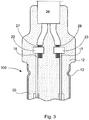
- Fig. 3 now shows an advantageous embodiment of an electrical contact of the sensor according to Fig. 2 in detail according to an embodiment of the present invention.
- the electrical contact serves to an electrical conductor 26 with a sensor 100 according to FIGS. 1 and 2 , which exemplifies a variety of sensors or actuators, electrically and mechanically contact.
- the electrical conductor 26 is electrically and mechanically connected in the upper region of the sensor 100 with the contact elements 22, 23.
- a possible connection technique is a crimp contact, in which the ends of the electrical conductor 26, 27, 28 are connected to the contact elements 22, 23 by squeezing.
- the connection elements 17, 18 establish the further contact with the coil or the coil wire.
- the connecting elements 17, 18 may be made of copper, steel, aluminum or other electrically conductive material, for example.
- the connections, ie the ends 27, 28 of the electrical conductor 26, the contact elements 22, 23 and the second contact elements 17, 18 are surrounded by a plastic covering 20 applied by extrusion coating.
- CCS Copper Cladded Steel.
- the combination of the contact elements 22, 23 with the CCS strand in the connection region of the electrical conductor 26 advantageously enables the mechanically and thermally stable contacting according to the invention between the sensor and a corresponding electronic evaluation unit and at the same time a high-quality electrical contacting.
- the physical properties of copper favor the mechanical contacting by squeezing, soldering or similar joining techniques.
- the electrical conductor 26 in the terminal area is more resistant to corrosion than conventional electrical steel conductors.
- the mechanically more stable steel core allows a contact that is resistant to high mechanical and thermal loads.
- the conductor ends 27, 28 of the electrical conductor 26 can advantageously be embodied as a strand or as a solid single conductor. According to the invention, provision must be made for the material thickness of the steel-that is to say a single or multiple cores in a strand-to be sufficiently large.
- the proportion of copper ie, the thickness of the copper jacket
- the proportion of copper is large enough to allow a sufficient deformation of the copper wire even when squeezing the line.
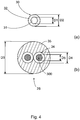
- Fig. 4 (a) shows by way of example a cross section through an electrical single conductor 30 of a strand, which can be used for electrical contacting according to the present invention.
- the single conductor has a core 31 with a diameter D1 and a jacket 32 with a diameter D2.
- the core can be advantageously made of steel and the sheath of copper or a copper alloy.
- the jacket can be very thin for most applications so that there is a ratio of D1 to (D2-D1) of more than 10 to 1.
- D1 to (D2-D1) The properties of the materials and for the core and the mantle have already been referred to Fig. 1 described and apply accordingly for the individual ladder Fig. 4 (a) ,
- Fig. 4 (b) shows by way of example a cross section through an electrical conductor 26 according to an advantageous embodiment of the invention.
- the embodiment of the conductor 26 explained below is located at least in a last section of the electrical conductor.
- an electrical conductor 26 of any length can be provided which has the corresponding advantageous properties over the entire length (ie the corresponding cross-sections).
- the criteria which are to be taken as the basis of the dimensioning of the strand according to the invention advantageously include the following aspects: the resistance to bending changes, the impact resistance to cable tie mounting, the fatigue strength, the tightness of the encapsulation of a sensor or actuator with the contact according to the invention and their low contact resistance. According to Fig.
- the electrical conductor 26 at one end (27 or 28 as shown Fig. 2 ) from a strand 300, which has a plurality (eg advantageously 19 or 20) individual conductors 30, each having a core 31 made of a mechanically robust material, such as steel, and a thin shell 32 made of a softer material, such as copper.
- the electrical conductor 26 advantageously has a diameter D3 of between, for example, 4 mm and 4.5 mm.
- the strand 300 with insulation 34 has a diameter D4 of about 1.5 mm.
- the diameter D5 of the strand itself is about 1 mm.
- the strand 300 is located, for example, in the contact element 22, 23 (in FIG Fig. 3 shown) for providing the electrical contact according to the invention.
- the contact element 22, which may consist of steel, aluminum, copper or the like and the conductor end 27 deformed and so brought into a close mechanical and electrical connection.
- the copper sheath 32 of the individual conductors 30 of the strand 300 may, due to the external pressure, which is exerted via the contact element 22, from an approximately circular cross-section to be deformed.
- the core 31 of the individual conductors 30 of the strand remains virtually unchanged. This advantageous effect of the invention is achieved in that the core 31 has a higher mechanical stability than the copper sheath 32.
- the diameter of the strand 300 according to the invention are chosen so that the aforementioned effect can occur.
- the better electrical conductivity of the copper jacket 32 has a positive effect to the extent that a low contact resistance between the contact element 22 and the strand 300 is formed.
- contacting alternatives are conceivable in addition to the crimping, such as welding, which is particularly advantageous for the steel core 31 in question.
- so-called resistance welding can also take place by means of "hot staking".
- By applying pressure via a screw or the like further advantageous contacting possibilities result according to the principle of the luster terminal.
- solutions are conceivable in which one or more joining techniques are combined with other joining techniques. So it is conceivable, for example, that the contact is partly soldered or welded and in addition via a crimp or a screw contact mechanical stability is generated. All forms of contact benefit from the inventive design.
- the above explanations mainly relate to a core and a jacket of an electrical-mechanical connection.
- the advantages of the present invention are also achieved by the use of multiple cores (e.g., as multiple inner conductors), or a multi-clad core in the form of a sequence of layers.
- Decide is the choice of materials for the core and the coat.
- the materials can also be chosen exactly the opposite way, so that the lower thermal conductivity of the core is instead fulfilled by the sheath.
- a massive single conductor can be chosen.
Landscapes
- Physics & Mathematics (AREA)
- General Physics & Mathematics (AREA)
- Connections Effected By Soldering, Adhesion, Or Permanent Deformation (AREA)
- Details Of Connecting Devices For Male And Female Coupling (AREA)
- Injection Moulding Of Plastics Or The Like (AREA)
Claims (7)
- Dispositif, lequel comprend un capteur ou un actionneur et des moyens d'accouplement, destinés à l'accouplement électrique et mécanique du capteur ou de l'actionneur,
les moyens d'accouplement comprenant un conducteur électrique (30) individuel, pourvu d'une âme (31) en une première matière et d'une gaine (32) en une deuxième matière et la première matière faisant preuve d'une conductibilité thermique inférieure à celle de la deuxième matière,
la première matière du conducteur électrique étant conçue sous la forme d'un conducteur interne, lequel comporte une section transversale circulaire et la deuxième matière étant conçue sous la forme d'un conducteur externe, lequel entoure le conducteur interne, caractérisé en ce que le capteur (100) est conçu pour une utilisation en tant que capteur dans une système antiblocage, destiné à capter la vitesse de rotation de roues,
le rapport du rayon interne du conducteur interne à l'épaisseur du conducteur externe étant supérieur à 10 : 1, le rapport étant compris entre 10 : 1 et 1000 : 1. - Dispositif selon la revendication 1, caractérisé en ce que la première matière supporte une charge mécanique supérieure à celle de la deuxième matière.
- Dispositif selon la revendication 1 ou 2, caractérisé en ce que la première matière fait preuve d'un coefficient de dilatation thermique plus faible que celui de la deuxième matière.
- Dispositif selon l'une quelconque des revendications précédentes, caractérisé en ce que la deuxième matière fait preuve d'une meilleure conductibilité électrique que la première matière.
- Dispositif selon l'une quelconque des revendications précédentes, caractérisé en ce que le capteur (100) est entouré au moins en partie d'une masse d'enrobage par injection, destinée à augmenter la stabilité mécanique des moyens d'accouplement.
- Dispositif selon l'une quelconque des revendications précédentes, caractérisé en ce que la première matière est de l'acier et la deuxième matière est du cuivre ou un alliage de cuivre.
- Dispositif selon l'une quelconque des revendications précédentes, caractérisé par un élément d'accouplement, notamment une prise d'accouplement, un manchon d'accouplement ou un connecteur d'accouplement pour l'accouplement électrique et mécanique ultérieur du conducteur électrique avec un système électronique destiné à faire fonctionner le capteur ou l'actionneur.
Applications Claiming Priority (2)
| Application Number | Priority Date | Filing Date | Title |
|---|---|---|---|
| DE102006060648A DE102006060648A1 (de) | 2006-12-21 | 2006-12-21 | Vorrichtung mit einem Sensor und Koppelmitteln |
| PCT/EP2007/009751 WO2008083785A1 (fr) | 2006-12-21 | 2007-11-10 | Dispositif doté d'un capteur et de moyens de couplage |
Publications (2)
| Publication Number | Publication Date |
|---|---|
| EP2104836A1 EP2104836A1 (fr) | 2009-09-30 |
| EP2104836B1 true EP2104836B1 (fr) | 2018-10-31 |
Family
ID=39420506
Family Applications (1)
| Application Number | Title | Priority Date | Filing Date |
|---|---|---|---|
| EP07819743.1A Active EP2104836B1 (fr) | 2006-12-21 | 2007-11-10 | Dispositif doté d'un capteur et de moyens de couplage |
Country Status (5)
| Country | Link |
|---|---|
| US (1) | US8006549B2 (fr) |
| EP (1) | EP2104836B1 (fr) |
| CN (1) | CN101542239B (fr) |
| DE (1) | DE102006060648A1 (fr) |
| WO (1) | WO2008083785A1 (fr) |
Families Citing this family (18)
| Publication number | Priority date | Publication date | Assignee | Title |
|---|---|---|---|---|
| DE102008029192A1 (de) * | 2008-03-13 | 2009-09-24 | Epcos Ag | Fühler zum Erfassen einer physikalischen Größe und Verfahren zur Herstellung des Fühlers |
| DE102009014799A1 (de) * | 2009-03-25 | 2010-09-30 | Knorr-Bremse Systeme für Nutzfahrzeuge GmbH | Einrichtung zur Bremsbelagverschleißüberwachung einer Bremse |
| DE102011084247A1 (de) | 2010-10-08 | 2012-04-12 | Ifm Electronic Gmbh | Mechatronisches Strömungsmessgerät |
| DE102010050754B4 (de) * | 2010-11-10 | 2015-07-30 | Integrated Dynamics Engineering Gmbh | Verbesserter Sensor-/Aktor-Korpus |
| FR2979570B1 (fr) * | 2011-09-01 | 2013-09-13 | Schneider Electric Ind Sas | Dispositif de controle de niveau de resine pour le remplissage d'un detecteur avec zone d'epargne |
| EP2704327A1 (fr) * | 2012-09-04 | 2014-03-05 | Optosys SA | Procédé de fabrication d'un commutateur de proximité inductif |
| DE102013202966B3 (de) * | 2013-02-22 | 2014-04-10 | Ifm Electronic Gmbh | Näherungsschalter mit einem Kabelanschluss |
| JP6111750B2 (ja) * | 2013-03-08 | 2017-04-12 | オムロン株式会社 | 電子機器 |
| JP6694232B2 (ja) * | 2014-12-19 | 2020-05-13 | 日立金属株式会社 | センサ付きケーブル |
| CA3014249C (fr) * | 2016-02-15 | 2023-05-09 | Hyperion Sensors Inc. | Procedes et systemes de detection optique pour des applications electriques, et leur construction |
| DE102016220032A1 (de) * | 2016-10-14 | 2018-04-19 | Robert Bosch Gmbh | Sensorvorrichtung für ein Fahrzeug, Kraftfahrzeug |
| JP6352557B1 (ja) * | 2017-03-24 | 2018-07-04 | 株式会社芝浦電子 | センサ素子、及び、センサ素子の製造方法 |
| DE102017111857A1 (de) * | 2017-05-31 | 2018-12-06 | Schaeffler Technologies AG & Co. KG | Hybridmodul einer monolithischen Baugruppe mit einem elektrischen Leiter |
| WO2019023794A1 (fr) | 2017-08-01 | 2019-02-07 | Hyperion Sensors Inc. | Procédés et systèmes de détection optique pour transformateurs et leur construction |
| JP6868514B2 (ja) * | 2017-09-12 | 2021-05-12 | 日立Astemo株式会社 | 回転検出器 |
| DE102017217494A1 (de) * | 2017-09-29 | 2019-04-04 | Micro-Epsilon Messtechnik Gmbh & Co. Kg | Kontaktlos arbeitender Wegsensor |
| CN109724734B (zh) * | 2019-01-22 | 2023-10-03 | 杭州瑞必莅机器人科技有限公司 | 一种消除耦合的单向测力装置 |
| DE202019004415U1 (de) * | 2019-10-28 | 2019-11-06 | K.W.H. Ciclosport Vertriebs GmbH | Sensorvorrichtung |
Family Cites Families (9)
| Publication number | Priority date | Publication date | Assignee | Title |
|---|---|---|---|---|
| US2420291A (en) * | 1940-07-22 | 1947-05-13 | Nat Standard Co | Electrodepositing copper upon steel wire |
| DD229242A1 (de) * | 1984-11-21 | 1985-10-30 | Kabelwerk Lausitz Veb | Kraftfahrzeug-leitung mit zugfester leiterkonstruktion |
| US5118906A (en) | 1989-12-14 | 1992-06-02 | Sumitomo Electric Industries, Ltd. | Wire conductors for automobiles |
| JPH0465022A (ja) | 1990-07-02 | 1992-03-02 | Sumitomo Electric Ind Ltd | 自動車用電線導体 |
| US5278496A (en) | 1992-05-22 | 1994-01-11 | Component Sales & Consultants, Inc. | High output and environmentally impervious variable reluctance sensor |
| JPH09147631A (ja) | 1995-09-20 | 1997-06-06 | Denso Corp | 検出器用のリード線 |
| US5712562A (en) * | 1995-10-13 | 1998-01-27 | Bently Nevada Corporation | Encapsulated transducer with an alignment plug and method of manufacture |
| US6850059B2 (en) | 2003-06-03 | 2005-02-01 | Delphi Technologies, Inc. | Vibration damping feature for a sensor assembly |
| DE102006021018B4 (de) * | 2006-05-05 | 2014-08-14 | Wabco Gmbh | Induktiver Sensor |
-
2006
- 2006-12-21 DE DE102006060648A patent/DE102006060648A1/de not_active Withdrawn
-
2007
- 2007-11-10 WO PCT/EP2007/009751 patent/WO2008083785A1/fr not_active Ceased
- 2007-11-10 US US12/312,693 patent/US8006549B2/en active Active
- 2007-11-10 EP EP07819743.1A patent/EP2104836B1/fr active Active
- 2007-11-10 CN CN2007800434704A patent/CN101542239B/zh active Active
Non-Patent Citations (1)
| Title |
|---|
| None * |
Also Published As
| Publication number | Publication date |
|---|---|
| US8006549B2 (en) | 2011-08-30 |
| CN101542239A (zh) | 2009-09-23 |
| DE102006060648A1 (de) | 2008-06-26 |
| EP2104836A1 (fr) | 2009-09-30 |
| CN101542239B (zh) | 2011-04-20 |
| WO2008083785A1 (fr) | 2008-07-17 |
| US20100064788A1 (en) | 2010-03-18 |
Similar Documents
| Publication | Publication Date | Title |
|---|---|---|
| EP2104836B1 (fr) | Dispositif doté d'un capteur et de moyens de couplage | |
| EP2954537B1 (fr) | Câble hybride, procédé de fabrication de celui-ci et utilisation d'un tel câble hybride | |
| DE102018005264B4 (de) | Draht mit Anschluss, Verbindervorrichtung und Herstellungsverfahren | |
| AT12838U1 (de) | Sensoradapterschaltungsgehäuseaufbau und verfahren zu dessen herstellung | |
| DE112008003375T5 (de) | Wasserabdichtverfahren für einen Draht und Draht, welcher ein wasserdichtes Teil aufweist, welches durch das Wasserabdichtverfahren gebildet ist | |
| AT12799U1 (de) | Temperatursensor-anordnung und herstellungsverfahren dafür | |
| DE4033846C2 (fr) | ||
| EP0083350B1 (fr) | Entree de cable de raccordement dans un appareil electrique | |
| EP1683235B1 (fr) | Connexion entre un câble coaxial et un connecteur et procédé de réalisation | |
| DE102019107581B4 (de) | Verbundkabel | |
| DE102018209699B4 (de) | Verbinder | |
| DE112008003346T5 (de) | Elektrisches Kabelbündel mit wasserdichtem Verbinder | |
| EP2201578B1 (fr) | Raccord électrique flexible | |
| DE112017001208T5 (de) | Widerstand | |
| DE102010013500A1 (de) | Steckervorrichtung und Verfahren zur Herstellung der Steckervorrichtung | |
| EP3369099A1 (fr) | Ligne électrique | |
| DE102016206961B4 (de) | Multifunktionskabel | |
| DE202007018270U1 (de) | Vorrichtung mit einem Sensor und Koppelmitteln | |
| DE102017130243A1 (de) | Struktur zur verhinderung einer kabelabtrennung | |
| DE29912812U1 (de) | Stecker-Schutzvorrichtung | |
| EP2874234B1 (fr) | Procédé d'isolation étanche d'un point de connexion entre un conducteur et un élément de contact | |
| DE10054419A1 (de) | Leitungsdurchführung | |
| DE3012321A1 (de) | Zwei- oder mehrleiterkabel | |
| DE102017208884A1 (de) | Elektrische Verbindungseinheit und Verfahren zu deren Herstellung | |
| EP1117274B1 (fr) | Dispositif de chauffage électrique |
Legal Events
| Date | Code | Title | Description |
|---|---|---|---|
| PUAI | Public reference made under article 153(3) epc to a published international application that has entered the european phase |
Free format text: ORIGINAL CODE: 0009012 |
|
| 17P | Request for examination filed |
Effective date: 20090721 |
|
| AK | Designated contracting states |
Kind code of ref document: A1 Designated state(s): AT BE BG CH CY CZ DE DK EE ES FI FR GB GR HU IE IS IT LI LT LU LV MC MT NL PL PT RO SE SI SK TR |
|
| 17Q | First examination report despatched |
Effective date: 20091216 |
|
| DAX | Request for extension of the european patent (deleted) | ||
| REG | Reference to a national code |
Ref country code: DE Ref legal event code: R079 Ref document number: 502007016469 Country of ref document: DE Free format text: PREVIOUS MAIN CLASS: G01D0011240000 Ipc: G01P0001000000 |
|
| GRAP | Despatch of communication of intention to grant a patent |
Free format text: ORIGINAL CODE: EPIDOSNIGR1 |
|
| RIC1 | Information provided on ipc code assigned before grant |
Ipc: G01P 1/00 20060101AFI20180615BHEP Ipc: G01D 11/24 20060101ALI20180615BHEP Ipc: G01P 1/02 20060101ALI20180615BHEP Ipc: H01B 7/18 20060101ALI20180615BHEP |
|
| INTG | Intention to grant announced |
Effective date: 20180712 |
|
| GRAS | Grant fee paid |
Free format text: ORIGINAL CODE: EPIDOSNIGR3 |
|
| GRAA | (expected) grant |
Free format text: ORIGINAL CODE: 0009210 |
|
| AK | Designated contracting states |
Kind code of ref document: B1 Designated state(s): AT BE BG CH CY CZ DE DK EE ES FI FR GB GR HU IE IS IT LI LT LU LV MC MT NL PL PT RO SE SI SK TR |
|
| REG | Reference to a national code |
Ref country code: CH Ref legal event code: EP Ref country code: GB Ref legal event code: FG4D Free format text: NOT ENGLISH |
|
| REG | Reference to a national code |
Ref country code: AT Ref legal event code: REF Ref document number: 1060026 Country of ref document: AT Kind code of ref document: T Effective date: 20181115 |
|
| REG | Reference to a national code |
Ref country code: DE Ref legal event code: R096 Ref document number: 502007016469 Country of ref document: DE |
|
| REG | Reference to a national code |
Ref country code: IE Ref legal event code: FG4D Free format text: LANGUAGE OF EP DOCUMENT: GERMAN |
|
| REG | Reference to a national code |
Ref country code: SE Ref legal event code: TRGR |
|
| REG | Reference to a national code |
Ref country code: NL Ref legal event code: MP Effective date: 20181031 |
|
| REG | Reference to a national code |
Ref country code: LT Ref legal event code: MG4D |
|
| PG25 | Lapsed in a contracting state [announced via postgrant information from national office to epo] |
Ref country code: ES Free format text: LAPSE BECAUSE OF FAILURE TO SUBMIT A TRANSLATION OF THE DESCRIPTION OR TO PAY THE FEE WITHIN THE PRESCRIBED TIME-LIMIT Effective date: 20181031 Ref country code: IS Free format text: LAPSE BECAUSE OF FAILURE TO SUBMIT A TRANSLATION OF THE DESCRIPTION OR TO PAY THE FEE WITHIN THE PRESCRIBED TIME-LIMIT Effective date: 20190228 Ref country code: LT Free format text: LAPSE BECAUSE OF FAILURE TO SUBMIT A TRANSLATION OF THE DESCRIPTION OR TO PAY THE FEE WITHIN THE PRESCRIBED TIME-LIMIT Effective date: 20181031 Ref country code: BG Free format text: LAPSE BECAUSE OF FAILURE TO SUBMIT A TRANSLATION OF THE DESCRIPTION OR TO PAY THE FEE WITHIN THE PRESCRIBED TIME-LIMIT Effective date: 20190131 Ref country code: FI Free format text: LAPSE BECAUSE OF FAILURE TO SUBMIT A TRANSLATION OF THE DESCRIPTION OR TO PAY THE FEE WITHIN THE PRESCRIBED TIME-LIMIT Effective date: 20181031 Ref country code: LV Free format text: LAPSE BECAUSE OF FAILURE TO SUBMIT A TRANSLATION OF THE DESCRIPTION OR TO PAY THE FEE WITHIN THE PRESCRIBED TIME-LIMIT Effective date: 20181031 Ref country code: PL Free format text: LAPSE BECAUSE OF FAILURE TO SUBMIT A TRANSLATION OF THE DESCRIPTION OR TO PAY THE FEE WITHIN THE PRESCRIBED TIME-LIMIT Effective date: 20181031 |
|
| PG25 | Lapsed in a contracting state [announced via postgrant information from national office to epo] |
Ref country code: GR Free format text: LAPSE BECAUSE OF FAILURE TO SUBMIT A TRANSLATION OF THE DESCRIPTION OR TO PAY THE FEE WITHIN THE PRESCRIBED TIME-LIMIT Effective date: 20190201 Ref country code: NL Free format text: LAPSE BECAUSE OF FAILURE TO SUBMIT A TRANSLATION OF THE DESCRIPTION OR TO PAY THE FEE WITHIN THE PRESCRIBED TIME-LIMIT Effective date: 20181031 Ref country code: PT Free format text: LAPSE BECAUSE OF FAILURE TO SUBMIT A TRANSLATION OF THE DESCRIPTION OR TO PAY THE FEE WITHIN THE PRESCRIBED TIME-LIMIT Effective date: 20190301 |
|
| REG | Reference to a national code |
Ref country code: CH Ref legal event code: PL |
|
| PG25 | Lapsed in a contracting state [announced via postgrant information from national office to epo] |
Ref country code: CZ Free format text: LAPSE BECAUSE OF FAILURE TO SUBMIT A TRANSLATION OF THE DESCRIPTION OR TO PAY THE FEE WITHIN THE PRESCRIBED TIME-LIMIT Effective date: 20181031 Ref country code: LU Free format text: LAPSE BECAUSE OF NON-PAYMENT OF DUE FEES Effective date: 20181110 Ref country code: IT Free format text: LAPSE BECAUSE OF FAILURE TO SUBMIT A TRANSLATION OF THE DESCRIPTION OR TO PAY THE FEE WITHIN THE PRESCRIBED TIME-LIMIT Effective date: 20181031 Ref country code: DK Free format text: LAPSE BECAUSE OF FAILURE TO SUBMIT A TRANSLATION OF THE DESCRIPTION OR TO PAY THE FEE WITHIN THE PRESCRIBED TIME-LIMIT Effective date: 20181031 |
|
| REG | Reference to a national code |
Ref country code: DE Ref legal event code: R097 Ref document number: 502007016469 Country of ref document: DE |
|
| REG | Reference to a national code |
Ref country code: BE Ref legal event code: MM Effective date: 20181130 |
|
| REG | Reference to a national code |
Ref country code: IE Ref legal event code: MM4A |
|
| PG25 | Lapsed in a contracting state [announced via postgrant information from national office to epo] |
Ref country code: CH Free format text: LAPSE BECAUSE OF NON-PAYMENT OF DUE FEES Effective date: 20181130 Ref country code: RO Free format text: LAPSE BECAUSE OF FAILURE TO SUBMIT A TRANSLATION OF THE DESCRIPTION OR TO PAY THE FEE WITHIN THE PRESCRIBED TIME-LIMIT Effective date: 20181031 Ref country code: EE Free format text: LAPSE BECAUSE OF FAILURE TO SUBMIT A TRANSLATION OF THE DESCRIPTION OR TO PAY THE FEE WITHIN THE PRESCRIBED TIME-LIMIT Effective date: 20181031 Ref country code: MC Free format text: LAPSE BECAUSE OF FAILURE TO SUBMIT A TRANSLATION OF THE DESCRIPTION OR TO PAY THE FEE WITHIN THE PRESCRIBED TIME-LIMIT Effective date: 20181031 Ref country code: LI Free format text: LAPSE BECAUSE OF NON-PAYMENT OF DUE FEES Effective date: 20181130 Ref country code: SK Free format text: LAPSE BECAUSE OF FAILURE TO SUBMIT A TRANSLATION OF THE DESCRIPTION OR TO PAY THE FEE WITHIN THE PRESCRIBED TIME-LIMIT Effective date: 20181031 |
|
| PLBE | No opposition filed within time limit |
Free format text: ORIGINAL CODE: 0009261 |
|
| STAA | Information on the status of an ep patent application or granted ep patent |
Free format text: STATUS: NO OPPOSITION FILED WITHIN TIME LIMIT |
|
| 26N | No opposition filed |
Effective date: 20190801 |
|
| PG25 | Lapsed in a contracting state [announced via postgrant information from national office to epo] |
Ref country code: IE Free format text: LAPSE BECAUSE OF NON-PAYMENT OF DUE FEES Effective date: 20181110 Ref country code: SI Free format text: LAPSE BECAUSE OF FAILURE TO SUBMIT A TRANSLATION OF THE DESCRIPTION OR TO PAY THE FEE WITHIN THE PRESCRIBED TIME-LIMIT Effective date: 20181031 |
|
| PG25 | Lapsed in a contracting state [announced via postgrant information from national office to epo] |
Ref country code: BE Free format text: LAPSE BECAUSE OF NON-PAYMENT OF DUE FEES Effective date: 20181130 |
|
| REG | Reference to a national code |
Ref country code: AT Ref legal event code: MM01 Ref document number: 1060026 Country of ref document: AT Kind code of ref document: T Effective date: 20181110 |
|
| PG25 | Lapsed in a contracting state [announced via postgrant information from national office to epo] |
Ref country code: MT Free format text: LAPSE BECAUSE OF FAILURE TO SUBMIT A TRANSLATION OF THE DESCRIPTION OR TO PAY THE FEE WITHIN THE PRESCRIBED TIME-LIMIT Effective date: 20181031 Ref country code: AT Free format text: LAPSE BECAUSE OF NON-PAYMENT OF DUE FEES Effective date: 20181110 |
|
| PG25 | Lapsed in a contracting state [announced via postgrant information from national office to epo] |
Ref country code: TR Free format text: LAPSE BECAUSE OF FAILURE TO SUBMIT A TRANSLATION OF THE DESCRIPTION OR TO PAY THE FEE WITHIN THE PRESCRIBED TIME-LIMIT Effective date: 20181031 |
|
| PG25 | Lapsed in a contracting state [announced via postgrant information from national office to epo] |
Ref country code: HU Free format text: LAPSE BECAUSE OF FAILURE TO SUBMIT A TRANSLATION OF THE DESCRIPTION OR TO PAY THE FEE WITHIN THE PRESCRIBED TIME-LIMIT; INVALID AB INITIO Effective date: 20071110 Ref country code: CY Free format text: LAPSE BECAUSE OF FAILURE TO SUBMIT A TRANSLATION OF THE DESCRIPTION OR TO PAY THE FEE WITHIN THE PRESCRIBED TIME-LIMIT Effective date: 20181031 |
|
| REG | Reference to a national code |
Ref country code: DE Ref legal event code: R081 Ref document number: 502007016469 Country of ref document: DE Owner name: ZF CV SYSTEMS EUROPE BV, BE Free format text: FORMER OWNER: WABCO GMBH, 30453 HANNOVER, DE Ref country code: DE Ref legal event code: R081 Ref document number: 502007016469 Country of ref document: DE Owner name: ZF CV SYSTEMS HANNOVER GMBH, DE Free format text: FORMER OWNER: WABCO GMBH, 30453 HANNOVER, DE |
|
| REG | Reference to a national code |
Ref country code: DE Ref legal event code: R081 Ref document number: 502007016469 Country of ref document: DE Owner name: ZF CV SYSTEMS EUROPE BV, BE Free format text: FORMER OWNER: ZF CV SYSTEMS HANNOVER GMBH, 30453 HANNOVER, DE |
|
| P01 | Opt-out of the competence of the unified patent court (upc) registered |
Effective date: 20230528 |
|
| PGFP | Annual fee paid to national office [announced via postgrant information from national office to epo] |
Ref country code: GB Payment date: 20240919 Year of fee payment: 18 |
|
| PGFP | Annual fee paid to national office [announced via postgrant information from national office to epo] |
Ref country code: FR Payment date: 20240909 Year of fee payment: 18 |
|
| PGFP | Annual fee paid to national office [announced via postgrant information from national office to epo] |
Ref country code: SE Payment date: 20250910 Year of fee payment: 19 |
|
| PGFP | Annual fee paid to national office [announced via postgrant information from national office to epo] |
Ref country code: DE Payment date: 20250916 Year of fee payment: 19 |