EP2105250B1 - Procédé de rectification sans centre - Google Patents
Procédé de rectification sans centre Download PDFInfo
- Publication number
- EP2105250B1 EP2105250B1 EP08738598.5A EP08738598A EP2105250B1 EP 2105250 B1 EP2105250 B1 EP 2105250B1 EP 08738598 A EP08738598 A EP 08738598A EP 2105250 B1 EP2105250 B1 EP 2105250B1
- Authority
- EP
- European Patent Office
- Prior art keywords
- workpiece
- blade
- axis
- diameter
- regulating wheel
- Prior art date
- Legal status (The legal status is an assumption and is not a legal conclusion. Google has not performed a legal analysis and makes no representation as to the accuracy of the status listed.)
- Active
Links
Images



Classifications
-
- B—PERFORMING OPERATIONS; TRANSPORTING
- B24—GRINDING; POLISHING
- B24B—MACHINES, DEVICES, OR PROCESSES FOR GRINDING OR POLISHING; DRESSING OR CONDITIONING OF ABRADING SURFACES; FEEDING OF GRINDING, POLISHING, OR LAPPING AGENTS
- B24B5/00—Machines or devices designed for grinding surfaces of revolution on work, including those which also grind adjacent plane surfaces; Accessories therefor
- B24B5/18—Machines or devices designed for grinding surfaces of revolution on work, including those which also grind adjacent plane surfaces; Accessories therefor involving centreless means for supporting, guiding, floating or rotating work
Definitions
- the present invention relates to centerless grinding methods in the same technical field as centerless grinding methods according to the preambles of Claims 1 and 2, and that such methods according to the preambles of Claims 1 and 2 are disclosed in JP 406246608 .
- a centerless grinding method is a grinding method in which grinding is performed with a workpiece being rotatably supported not at its center but through contact with three members, i.e., a grinding wheel, a regulating wheel, and a blade (see JP 2004136391 and JP 40626608 ).
- a throughfeed method As a workpiece feeding method, there is known a throughfeed method, and this method is a highly efficient in mass production, wherein grinding is performed such that a workpiece is advanced virtually along direction of the rotational axis of a wheel and passed through a space between two wheels with the regulating wheel given a slight feed angle.
- a guide plate for guiding movement of the workpiece.
- the present invention has been devised in view of the foregoing problems and has an object to provide a centerless grinding method which facilitates a tooling change and enables automation.
- the present invention provides centerless grinding methods according to claims 1 and 2.
- a tooling change can be automated for such workpieces of various sizes including a workpiece of an extremely large diameter in such a manner that the blade, the grinding wheel, and the regulating wheel are each moved by a servomotor and the operation amount of each servomotor is arithmetically controlled.
- FIG. 1 shows a configuration of a centerless grinding device for implementing a centerless grinding method according to one embodiment.
- a centerless grinding device 1 has a bed 5 secured on a device-mounting surface 3.
- a grinding wheel 7 Above a support surface 5a of the bed 5, there are disposed a grinding wheel 7, a regulating wheel 9, and a blade 11.
- the grinding wheel 7 is rotatably supported by a grinding wheel-driving system 13 mounted on the support surface 5a.
- a grinding wheel-dressing system 15 In the vicinity of the grinding wheel 7, there are also disposed a grinding wheel-dressing system 15 and a grinding wheel-sliding system 17.
- the regulating wheel 9 is disposed opposed to the grinding wheel 7 and rotatably supported by a regulating wheel-driving system 23 that is disposed above the support surface 5a through a lower sliding table 19 and an upper sliding system 21. In the vicinity of the regulating wheel 9, there is disposed a regulating wheel-dressing system 25. Moreover, guide plates 26 are disposed on workpiece-feeding and ejecting sides of the regulating wheel 9. When feeding and ejecting a workpiece, the workpiece is fed into a space between the grinding wheel 7 and the regulating wheel 9 while being kept in contact with and supported by the guide plate 26, so that three contacts of the workpiece with the grinding wheel 7, the regulating wheel 9, and the blade 11 can be appropriately positioned to achieve desired grinding results. It should be noted that the workpiece-feeding side corresponds to a front surface of the paper of Fig. 1 .
- the blade 11 is supported slidable in a given direction through a blade-sliding system 27 mounted on the support surface 5a.
- the plane of paper is a plane perpendicular to a rotational axis of a workpiece, and in this plane, Y and X axes, which are perpendicular to each other, are set for the sake of convenience.
- the X axis is a line parallel to the support surface 5a of the bed 5, and consequently, the Y axis is a line perpendicular thereto.
- the blade 11 is disposed slidable along a first straight line 101, i.e., the Y axis, through the blade-sliding system 27.
- the grinding wheel 7 is disposed slidable along a second straight line 102, i.e., the X axis, through the grinding wheel-sliding system 17.
- the lower sliding table 19 is a portion having a generally wedge-like shape in the paper of Fig. 1 and provided with a lower surface 19a in contact with the support surface 5a of the bed 5 and an upper surface 19b mounted with the upper sliding system 21.
- the angle made between the lower surface 19a and the upper surface 19b is designated angle ⁇ 2.
- the regulating wheel 9 is disposed slidable along a third straight line 103, which intersects with the second straight line 102, i.e., the X axis, at an angle ⁇ 2, through the upper sliding system 21.
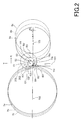
- a centerless grinding method using the centerless grinding device with the above configuration will be described with reference to Fig. 2 .
- a workpiece feeding method there is adopted a throughfeed method.
- the workpiece is fed from the near side in the paper of Fig. 2 into a space between the grinding wheel 7, the regulating wheel 9, and the blade 11 while being guided by the guide plate 26, advanced to pass through the space, and ejected through the space from the remote side in the paper of Fig. 2 while being guided by a guide plate similar to that on the near side.
- grinding can be efficiently performed by continuously feeding, passing, and ejecting a plurality of workpieces with the guide plates 26.
- the tooling change is performed as follows.
- the blade 11 is moved in the negative direction of the Y axis along the first straight line 101 with an increase in diameter of the workpiece
- the grinding wheel 7 is moved in the negative direction of the X axis along the second straight line 102 with an increase in diameter of the workpiece
- the regulating wheel 9 is moved in the positive direction of the Y axis and also in the positive direction of the X axis along the third straight line 103 with an increase in diameter of the workpiece.
- the regulating wheel 9 is moved farther rightward and slightly obliquely upward in the paper of Fig. 2 from symbol 9b to symbol 9c.
- the blade 11, the grinding wheel 7, and the regulating wheel 9 are moved in opposite directions from those described above, respectively.
- the angle between the line segment O1B1 and the contact angular position reference line S, the angle between the line segment O2B2 and the contact angular position reference line S, and the angle between the line segment O3B3 and the contact angular position reference line S are the angle ⁇ and equal to each other.
- the angle between the line segment O1R1 and the contact angular position reference line S, the angle between the line segment O2R2 and the contact angular position reference line S, and the angle between the line segment 03R3 and the contact angular position reference line S are the angle ⁇ and equal to each other.
- the contact R always changes in position on a line parallel to the third straight line 103 and the contact B always changes in position on a line parallel to the first straight line 101. Accordingly, the contact R is always located in the same direction with respect to the rotational center of the regulating wheel 9, and therefore, the guide plate 26 disposed therewith can be located always at the same position of the regulating wheel 9.
- the guide plate 26 can be secured in such a manner as to be movable along with the regulating wheel 9, so that the necessity of adjusting the position and posture of the guide plate every time a tooling change is performed as in the prior art can be eliminated to thereby suppress a decrease in efficiency and an increase in cost due to a tooling change. This also reduces the time necessary to perform a tooling change. Particularly, large components such as the blade have been difficult to replace, but the present embodiment is significantly effective in reducing the working time since large components such as the blade do not have to be replaced.
- the blade 11, the grinding wheel 7, and the regulating wheel 9 described above are each moved with a servomotor disposed in corresponding one of the driving or sliding system, wherein the operation amount of each servomotor is calculated and controlled. This enables automation of a tooling change for grinding a variety of workpieces as described above.
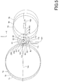
- the contact B since the contact B always changes in position on a line parallel to the first straight line 101, workpieces of various sizes including a workpiece of an extremely large diameter can be handled only by ascending and descending the blade without changing the blade itself. That is, when workpieces of different diameters are handled, by way of comparison, only by changing the position of the regulating wheel without moving the blade, as shown in Fig. 4 , the contact R can always be located at the same position on the regulating wheel but the contact B cannot always be located at the same potion on the blade. Therefore, if the diameter of a workpiece to be ground exceeds a given value, there will be a case that the contact B cannot be located on the blade.
- the blade 11 is moved in the negative direction of the Y axis along the first straight line 101 with an increase in diameter of the workpiece, and the grinding wheel 7 is moved in the negative direction of the X axis along the second straight line 102 with an increase in diameter of the workpiece, as in the first embodiment.
- the regulating wheel 9 is moved in the negative direction of the Y axis and also in the positive direction of the X axis along the third straight line 103 with an increase in diameter of the workpiece, unlike in the first embodiment.
- the third straight line 103 intersects with the second straight line 102, i.e., the Y axis, at an angle ⁇ 3.
- the angles ⁇ and ⁇ of the contact angular position reference line S with the line segments OB and OR are always constant ( ⁇ , ⁇ ⁇ 180 degrees) as in the first embodiment, and additionally in the present embodiment, when the contact of the workpiece with the grinding wheel is designated contact G, the angle ⁇ of the contact angular position reference line S with the line segment OG is always constant, too ( ⁇ ⁇ 180 degrees).
- a decrease in efficiency and an increase in cost due to a tooling change can be suppressed by securing the guide plate in such a manner as to be movable along with the regulating wheel 9, as in the first embodiment.
- the blade is just made ascendable and descendable, workpieces of various sizes including a workpiece of an extremely large diameter can be handled using a blade with a minimum thickness.
- the second embodiment is not suitable for a ring-like workpiece that tends to bend along direction of its diameter since the optimum compound angle of the angles ⁇ and ⁇ for maintaining processing accuracy at finishing tends to change with a change in diameter of the workpiece.
- the angle ⁇ 2 is so set as to permit the compound angle of the angles ⁇ and ⁇ to appropriately change in response to a change in diameter of the workpiece.
Landscapes
- Engineering & Computer Science (AREA)
- Mechanical Engineering (AREA)
- Grinding Of Cylindrical And Plane Surfaces (AREA)
Claims (2)
- Procédé de rectification sans pointes, dans lequel des axes Y et X, qui sont perpendiculaires l'un à l'autre dans un plan perpendiculaire à un axe de rotation d'une pièce de fabrication, sont désignés première et deuxième droites (101, 102), respectivement, le procédé comprenant :la disposition d'une lame (11) qui est coulissante le long de ladite première droite (101) ;la disposition d'une meule (7) qui est coulissante le long de ladite deuxième droite (102) ; etla disposition d'une meule d'entraînement (9) qui est coulissante le long d'une troisième droite (103) coupant ladite deuxième droite (102) selon un angle θ2,dans lequel lors d'un changement d'outillage, ladite lame (11) se déplace dans une direction négative dudit axe Y avec une augmentation de diamètre de ladite pièce de fabrication,ladite meule (7) se déplace dans une direction négative dudit axe X avec une augmentation de diamètre de ladite pièce de fabrication,ladite meule d'entraînement (9) se déplace dans une direction positive dudit axe Y et également dans une direction positive dudit axe X avec une augmentation de diamètre de ladite pièce de fabrication,moyennant quoi lorsque des contacts de ladite pièce de fabrication avec ladite lame (11) et ladite meule d'entraînement (9) sont désignés par contacts B et R, respectivement, un centre de ladite pièce de fabrication est désigné par centre O, et une ligne passant par ledit centre O et s'étendant parallèlement audit axe Y est désignée ligne de référence de position angulaire de contact S, le procédé étant caractérisé en ce que ledit changement d'outillage conjointement avec un changement de diamètre de ladite pièce de fabrication est réalisé de telle sorte que les angles α et β de ladite ligne de référence de position angulaire de contact S avec les segments de droite OB et OR soient toujours constants, moyennant quoi α, β < 180 degrés.
- Procédé de rectification sans pointes dans lequel les axes Y et X, qui sont perpendiculaires l'un à l'autre dans un plan perpendiculaire à un axe de rotation d'une pièce de fabrication, sont désignés première et deuxième droites (101, 102), respectivement, le procédé comprenant :la disposition d'une lame (11) qui est coulissante le long de ladite première droite (101) ;la disposition d'une meule (7) qui est coulissante le long de ladite deuxième droite (102) ; etla disposition d'une meule d'entraînement (9) qui est coulissante le long d'une troisième droite (103) coupant ladite deuxième droite (102) selon un angle θ3,dans lequel lors d'un changement d'outillage, ladite lame (11) se déplace dans une direction négative dudit axe Y avec une augmentation de diamètre de ladite pièce de fabrication,ladite meule (7) se déplace dans une direction négative dudit axe X avec une augmentation de diamètre de ladite pièce de fabrication,ladite meule d'entraînement (9) se déplace dans ladite direction négative dudit axe Y et également dans une direction positive dudit axe X avec une augmentation de diamètre de ladite pièce de fabrication,moyennant quoi lorsque des contacts de ladite pièce de fabrication avec ladite lame (11), ladite meule d'entraînement (9) et ladite meule (7) sont désignés par contacts B, R et G, respectivement, un centre de ladite pièce de fabrication est désigné par centre O, et une ligne passant par ledit centre O et s'étendant parallèlement audit axe Y est désignée ligne de référence de position angulaire de contact S, le procédé étant caractérisé en ce que ledit changement d'outillage conjointement avec un changement de diamètre de ladite pièce de fabrication est réalisé de telle sorte que les angles α, β et γ de ladite ligne de référence de position angulaire de contact S avec les segments de droite OB, OR et OG soient toujours constants, moyennant quoi α, β, γ < 180 degrés.
Applications Claiming Priority (2)
| Application Number | Priority Date | Filing Date | Title |
|---|---|---|---|
| JP2007312396A JP5057947B2 (ja) | 2007-12-03 | 2007-12-03 | センタレス研削方法 |
| PCT/JP2008/000996 WO2009072224A1 (fr) | 2007-12-03 | 2008-04-16 | Procédé de rectification sans centre |
Publications (3)
| Publication Number | Publication Date |
|---|---|
| EP2105250A1 EP2105250A1 (fr) | 2009-09-30 |
| EP2105250A4 EP2105250A4 (fr) | 2014-06-11 |
| EP2105250B1 true EP2105250B1 (fr) | 2016-03-16 |
Family
ID=40717410
Family Applications (1)
| Application Number | Title | Priority Date | Filing Date |
|---|---|---|---|
| EP08738598.5A Active EP2105250B1 (fr) | 2007-12-03 | 2008-04-16 | Procédé de rectification sans centre |
Country Status (4)
| Country | Link |
|---|---|
| US (1) | US7997954B2 (fr) |
| EP (1) | EP2105250B1 (fr) |
| JP (1) | JP5057947B2 (fr) |
| WO (1) | WO2009072224A1 (fr) |
Families Citing this family (10)
| Publication number | Priority date | Publication date | Assignee | Title |
|---|---|---|---|---|
| DE102007030956A1 (de) * | 2007-07-04 | 2009-01-08 | The Gleason Works | Schlittenanordnung für eine Werkzeugmaschine |
| CN103481162B (zh) * | 2013-09-29 | 2016-08-10 | 吴鸣寰 | 一种制笔用台阶磨 |
| JP6287044B2 (ja) * | 2013-10-17 | 2018-03-07 | 株式会社ジェイテクト | ころ素材の研削方法及び研削装置 |
| CN103692315B (zh) * | 2013-12-31 | 2016-04-06 | 吴鸣寰 | 一种制笔头用两头台阶磨 |
| DE102014115149B3 (de) * | 2014-10-17 | 2016-01-21 | Schaudt Mikrosa Gmbh | Schleifmaschine, insbesondere kompakt gestaltete spitzenlose Schleifmaschine |
| JP6625463B2 (ja) * | 2015-03-31 | 2019-12-25 | 日本碍子株式会社 | 円柱部材の外周加工装置、及び円柱部材の製造方法 |
| JP2017039177A (ja) * | 2015-08-18 | 2017-02-23 | コマツNtc株式会社 | 研削盤および研削方法 |
| JP6674426B2 (ja) * | 2017-09-28 | 2020-04-01 | ミクロン精密株式会社 | センタレス研削装置およびワークの研削状態監視方法 |
| JP7540760B2 (ja) | 2022-10-03 | 2024-08-27 | ミクロン精密株式会社 | センタレス研削装置 |
| US12611746B1 (en) * | 2024-12-27 | 2026-04-28 | Tianjin University | Over-positioning grinding method of hard and brittle pipe fitting with large length-to-diameter ratio |
Family Cites Families (17)
| Publication number | Priority date | Publication date | Assignee | Title |
|---|---|---|---|---|
| US4150955A (en) * | 1974-05-01 | 1979-04-24 | The Manufacturers Brush Company | Deformable non-cellular polyurethane polishing wheel |
| US4083151A (en) * | 1977-06-06 | 1978-04-11 | Cincinnati Milacron Inc. | Angular feed centerless grinder |
| JPS5627766A (en) * | 1979-08-07 | 1981-03-18 | Suruga Seiki Kk | Genterless grinder with automated positioning |
| JPS59219139A (ja) * | 1983-05-27 | 1984-12-10 | Toyoda Mach Works Ltd | センタレス研削盤における心高制御装置 |
| JPS6025640A (ja) * | 1983-07-21 | 1985-02-08 | Toyoda Mach Works Ltd | 段付軸の成形加工方法 |
| JPH0829481B2 (ja) * | 1992-04-09 | 1996-03-27 | 株式会社東振テクニカル | 心なし研削盤のワークレスト |
| JPH06246608A (ja) * | 1993-02-26 | 1994-09-06 | Koyo Mach Ind Co Ltd | 心なし研削方法およびその装置 |
| JP3129911B2 (ja) * | 1994-07-06 | 2001-01-31 | ミクロン精密株式会社 | センターレスグラインダの調整方法 |
| US5567195A (en) * | 1995-01-10 | 1996-10-22 | Tufts Grinding, Inc. | Method and apparatus for grinding bars |
| US5643051A (en) * | 1995-06-16 | 1997-07-01 | The University Of Connecticut | Centerless grinding process and apparatus therefor |
| US5674106A (en) * | 1996-02-08 | 1997-10-07 | Royal Masters Grinders, Inc. | Centerless grinder assembly and method of operating the same |
| US5928065A (en) * | 1998-02-09 | 1999-07-27 | Cummins Engine Company, Inc. | Centerless grinding machine with optimal regulating wheel truing and dressing |
| JPH11347896A (ja) * | 1998-06-05 | 1999-12-21 | Nippon Seiko Kk | 芯無研削盤 |
| DE19940685A1 (de) * | 1999-08-27 | 2001-03-01 | Mikrosa Werkzeugmaschinen Gmbh | Verfahren zum spitzenlosen Schräg-Einstechschleifen und Schleifmaschine |
| DE10139894B4 (de) * | 2001-08-14 | 2009-09-10 | Erwin Junker Maschinenfabrik Gmbh | Verfahren und Vorrichtung zum spitzenlosen Rundschleifen |
| JP4107936B2 (ja) | 2002-10-17 | 2008-06-25 | 株式会社日進機械製作所 | センタレス研削装置 |
| US7677954B2 (en) * | 2007-05-21 | 2010-03-16 | Hall David R | O.D. centerless grinding machine |
-
2007
- 2007-12-03 JP JP2007312396A patent/JP5057947B2/ja active Active
-
2008
- 2008-04-16 EP EP08738598.5A patent/EP2105250B1/fr active Active
- 2008-04-16 US US12/160,435 patent/US7997954B2/en active Active
- 2008-04-16 WO PCT/JP2008/000996 patent/WO2009072224A1/fr not_active Ceased
Also Published As
| Publication number | Publication date |
|---|---|
| JP2009136924A (ja) | 2009-06-25 |
| US7997954B2 (en) | 2011-08-16 |
| US20100173571A1 (en) | 2010-07-08 |
| WO2009072224A1 (fr) | 2009-06-11 |
| EP2105250A1 (fr) | 2009-09-30 |
| EP2105250A4 (fr) | 2014-06-11 |
| JP5057947B2 (ja) | 2012-10-24 |
Similar Documents
| Publication | Publication Date | Title |
|---|---|---|
| EP2105250B1 (fr) | Procédé de rectification sans centre | |
| US10232467B2 (en) | Machines for the separative machining of plate-shaped workpieces | |
| US9776293B2 (en) | Eyeglass lens processing apparatus | |
| KR20130000101U (ko) | 경질 취성판의 둘레가장자리 가공장치 | |
| CN105799214A (zh) | 一种用于纸板加工自动裁边设备 | |
| KR101520306B1 (ko) | 판재 가공 시스템 | |
| JP6190654B2 (ja) | 削り代の均一化方法及び板材の周縁研削装置 | |
| CN204975149U (zh) | 可加工多种弹簧线的弹簧机 | |
| WO2010143234A1 (fr) | Dispositif de traitement de lentille | |
| KR20070080535A (ko) | 워크의 측변 가공장치 | |
| CN107378661A (zh) | 一种数控刀片磨床 | |
| JP2023093309A (ja) | 折割治具及び折割加工方法 | |
| US9796013B1 (en) | Tool holde panel mounting structure for spring making machine | |
| KR100932111B1 (ko) | 디스플레이용 박판유리 가공물의 면취부 연삭가공을 위한 자동화장치 및 그의 제어방법 | |
| KR20140032602A (ko) | 광범위한 가공 조건을 갖는 자동화 연삭기 | |
| CN206662960U (zh) | 一种自动研磨机 | |
| CN205932308U (zh) | 一种摩擦转盘式送料器 | |
| CN108098908A (zh) | 稳定定位打孔装置 | |
| CN202240741U (zh) | 一种用于无心磨床的阶梯式螺栓加工工装 | |
| CN211163265U (zh) | 一种全自动玻璃大角连线倒角机 | |
| CN107405752A (zh) | 用于无心圆磨削的装置和用于使用用于无心圆磨削的装置的方法 | |
| CN217800472U (zh) | 支架型cnc自动上下料设备 | |
| JP6134604B2 (ja) | 切削装置 | |
| JPH079325A (ja) | 定盤面の形成装置 | |
| CN209408017U (zh) | 一种快速装卸的键槽加工定位机构 |
Legal Events
| Date | Code | Title | Description |
|---|---|---|---|
| PUAI | Public reference made under article 153(3) epc to a published international application that has entered the european phase |
Free format text: ORIGINAL CODE: 0009012 |
|
| AK | Designated contracting states |
Kind code of ref document: A1 Designated state(s): AT BE BG CH CY CZ DE DK EE ES FI FR GB GR HR HU IE IS IT LI LT LU LV MC MT NL NO PL PT RO SE SI SK TR |
|
| 17P | Request for examination filed |
Effective date: 20100625 |
|
| RBV | Designated contracting states (corrected) |
Designated state(s): AT BE BG CH CY CZ DE DK EE ES FI FR GB GR HR HU IE IS IT LI LT LU LV MC MT NL NO PL PT RO SE SI SK TR |
|
| DAX | Request for extension of the european patent (deleted) | ||
| RIC1 | Information provided on ipc code assigned before grant |
Ipc: B24B 5/18 20060101AFI20140429BHEP |
|
| A4 | Supplementary search report drawn up and despatched |
Effective date: 20140509 |
|
| GRAP | Despatch of communication of intention to grant a patent |
Free format text: ORIGINAL CODE: EPIDOSNIGR1 |
|
| INTG | Intention to grant announced |
Effective date: 20150216 |
|
| GRAP | Despatch of communication of intention to grant a patent |
Free format text: ORIGINAL CODE: EPIDOSNIGR1 |
|
| INTG | Intention to grant announced |
Effective date: 20151008 |
|
| GRAS | Grant fee paid |
Free format text: ORIGINAL CODE: EPIDOSNIGR3 |
|
| GRAA | (expected) grant |
Free format text: ORIGINAL CODE: 0009210 |
|
| AK | Designated contracting states |
Kind code of ref document: B1 Designated state(s): AT BE BG CH CY CZ DE DK EE ES FI FR GB GR HR HU IE IS IT LI LT LU LV MC MT NL NO PL PT RO SE SI SK TR |
|
| REG | Reference to a national code |
Ref country code: GB Ref legal event code: FG4D |
|
| REG | Reference to a national code |
Ref country code: CH Ref legal event code: EP |
|
| REG | Reference to a national code |
Ref country code: IE Ref legal event code: FG4D |
|
| REG | Reference to a national code |
Ref country code: AT Ref legal event code: REF Ref document number: 780776 Country of ref document: AT Kind code of ref document: T Effective date: 20160415 |
|
| REG | Reference to a national code |
Ref country code: DE Ref legal event code: R096 Ref document number: 602008042814 Country of ref document: DE |
|
| REG | Reference to a national code |
Ref country code: SE Ref legal event code: TRGR |
|
| REG | Reference to a national code |
Ref country code: NL Ref legal event code: MP Effective date: 20160316 |
|
| REG | Reference to a national code |
Ref country code: LT Ref legal event code: MG4D |
|
| PG25 | Lapsed in a contracting state [announced via postgrant information from national office to epo] |
Ref country code: FI Free format text: LAPSE BECAUSE OF FAILURE TO SUBMIT A TRANSLATION OF THE DESCRIPTION OR TO PAY THE FEE WITHIN THE PRESCRIBED TIME-LIMIT Effective date: 20160316 Ref country code: NO Free format text: LAPSE BECAUSE OF FAILURE TO SUBMIT A TRANSLATION OF THE DESCRIPTION OR TO PAY THE FEE WITHIN THE PRESCRIBED TIME-LIMIT Effective date: 20160616 Ref country code: HR Free format text: LAPSE BECAUSE OF FAILURE TO SUBMIT A TRANSLATION OF THE DESCRIPTION OR TO PAY THE FEE WITHIN THE PRESCRIBED TIME-LIMIT Effective date: 20160316 Ref country code: GR Free format text: LAPSE BECAUSE OF FAILURE TO SUBMIT A TRANSLATION OF THE DESCRIPTION OR TO PAY THE FEE WITHIN THE PRESCRIBED TIME-LIMIT Effective date: 20160617 |
|
| REG | Reference to a national code |
Ref country code: AT Ref legal event code: MK05 Ref document number: 780776 Country of ref document: AT Kind code of ref document: T Effective date: 20160316 |
|
| PG25 | Lapsed in a contracting state [announced via postgrant information from national office to epo] |
Ref country code: LT Free format text: LAPSE BECAUSE OF FAILURE TO SUBMIT A TRANSLATION OF THE DESCRIPTION OR TO PAY THE FEE WITHIN THE PRESCRIBED TIME-LIMIT Effective date: 20160316 Ref country code: NL Free format text: LAPSE BECAUSE OF FAILURE TO SUBMIT A TRANSLATION OF THE DESCRIPTION OR TO PAY THE FEE WITHIN THE PRESCRIBED TIME-LIMIT Effective date: 20160316 Ref country code: LV Free format text: LAPSE BECAUSE OF FAILURE TO SUBMIT A TRANSLATION OF THE DESCRIPTION OR TO PAY THE FEE WITHIN THE PRESCRIBED TIME-LIMIT Effective date: 20160316 Ref country code: BE Free format text: LAPSE BECAUSE OF NON-PAYMENT OF DUE FEES Effective date: 20160430 |
|
| PG25 | Lapsed in a contracting state [announced via postgrant information from national office to epo] |
Ref country code: IS Free format text: LAPSE BECAUSE OF FAILURE TO SUBMIT A TRANSLATION OF THE DESCRIPTION OR TO PAY THE FEE WITHIN THE PRESCRIBED TIME-LIMIT Effective date: 20160716 Ref country code: EE Free format text: LAPSE BECAUSE OF FAILURE TO SUBMIT A TRANSLATION OF THE DESCRIPTION OR TO PAY THE FEE WITHIN THE PRESCRIBED TIME-LIMIT Effective date: 20160316 Ref country code: PL Free format text: LAPSE BECAUSE OF FAILURE TO SUBMIT A TRANSLATION OF THE DESCRIPTION OR TO PAY THE FEE WITHIN THE PRESCRIBED TIME-LIMIT Effective date: 20160316 |
|
| PG25 | Lapsed in a contracting state [announced via postgrant information from national office to epo] |
Ref country code: SK Free format text: LAPSE BECAUSE OF FAILURE TO SUBMIT A TRANSLATION OF THE DESCRIPTION OR TO PAY THE FEE WITHIN THE PRESCRIBED TIME-LIMIT Effective date: 20160316 Ref country code: CZ Free format text: LAPSE BECAUSE OF FAILURE TO SUBMIT A TRANSLATION OF THE DESCRIPTION OR TO PAY THE FEE WITHIN THE PRESCRIBED TIME-LIMIT Effective date: 20160316 Ref country code: ES Free format text: LAPSE BECAUSE OF FAILURE TO SUBMIT A TRANSLATION OF THE DESCRIPTION OR TO PAY THE FEE WITHIN THE PRESCRIBED TIME-LIMIT Effective date: 20160316 Ref country code: AT Free format text: LAPSE BECAUSE OF FAILURE TO SUBMIT A TRANSLATION OF THE DESCRIPTION OR TO PAY THE FEE WITHIN THE PRESCRIBED TIME-LIMIT Effective date: 20160316 Ref country code: PT Free format text: LAPSE BECAUSE OF FAILURE TO SUBMIT A TRANSLATION OF THE DESCRIPTION OR TO PAY THE FEE WITHIN THE PRESCRIBED TIME-LIMIT Effective date: 20160718 Ref country code: RO Free format text: LAPSE BECAUSE OF FAILURE TO SUBMIT A TRANSLATION OF THE DESCRIPTION OR TO PAY THE FEE WITHIN THE PRESCRIBED TIME-LIMIT Effective date: 20160316 |
|
| REG | Reference to a national code |
Ref country code: CH Ref legal event code: PL |
|
| REG | Reference to a national code |
Ref country code: DE Ref legal event code: R097 Ref document number: 602008042814 Country of ref document: DE |
|
| PG25 | Lapsed in a contracting state [announced via postgrant information from national office to epo] |
Ref country code: IT Free format text: LAPSE BECAUSE OF FAILURE TO SUBMIT A TRANSLATION OF THE DESCRIPTION OR TO PAY THE FEE WITHIN THE PRESCRIBED TIME-LIMIT Effective date: 20160316 Ref country code: BE Free format text: LAPSE BECAUSE OF FAILURE TO SUBMIT A TRANSLATION OF THE DESCRIPTION OR TO PAY THE FEE WITHIN THE PRESCRIBED TIME-LIMIT Effective date: 20160316 |
|
| PLBE | No opposition filed within time limit |
Free format text: ORIGINAL CODE: 0009261 |
|
| STAA | Information on the status of an ep patent application or granted ep patent |
Free format text: STATUS: NO OPPOSITION FILED WITHIN TIME LIMIT |
|
| REG | Reference to a national code |
Ref country code: IE Ref legal event code: MM4A |
|
| REG | Reference to a national code |
Ref country code: FR Ref legal event code: ST Effective date: 20161230 |
|
| PG25 | Lapsed in a contracting state [announced via postgrant information from national office to epo] |
Ref country code: FR Free format text: LAPSE BECAUSE OF NON-PAYMENT OF DUE FEES Effective date: 20160517 Ref country code: DK Free format text: LAPSE BECAUSE OF FAILURE TO SUBMIT A TRANSLATION OF THE DESCRIPTION OR TO PAY THE FEE WITHIN THE PRESCRIBED TIME-LIMIT Effective date: 20160316 Ref country code: CH Free format text: LAPSE BECAUSE OF NON-PAYMENT OF DUE FEES Effective date: 20160430 Ref country code: LI Free format text: LAPSE BECAUSE OF NON-PAYMENT OF DUE FEES Effective date: 20160430 |
|
| 26N | No opposition filed |
Effective date: 20161219 |
|
| PG25 | Lapsed in a contracting state [announced via postgrant information from national office to epo] |
Ref country code: BG Free format text: LAPSE BECAUSE OF FAILURE TO SUBMIT A TRANSLATION OF THE DESCRIPTION OR TO PAY THE FEE WITHIN THE PRESCRIBED TIME-LIMIT Effective date: 20160616 |
|
| GBPC | Gb: european patent ceased through non-payment of renewal fee |
Effective date: 20160616 |
|
| PG25 | Lapsed in a contracting state [announced via postgrant information from national office to epo] |
Ref country code: IE Free format text: LAPSE BECAUSE OF NON-PAYMENT OF DUE FEES Effective date: 20160416 Ref country code: SI Free format text: LAPSE BECAUSE OF FAILURE TO SUBMIT A TRANSLATION OF THE DESCRIPTION OR TO PAY THE FEE WITHIN THE PRESCRIBED TIME-LIMIT Effective date: 20160316 Ref country code: GB Free format text: LAPSE BECAUSE OF NON-PAYMENT OF DUE FEES Effective date: 20160616 |
|
| PG25 | Lapsed in a contracting state [announced via postgrant information from national office to epo] |
Ref country code: CY Free format text: LAPSE BECAUSE OF FAILURE TO SUBMIT A TRANSLATION OF THE DESCRIPTION OR TO PAY THE FEE WITHIN THE PRESCRIBED TIME-LIMIT Effective date: 20160316 Ref country code: HU Free format text: LAPSE BECAUSE OF FAILURE TO SUBMIT A TRANSLATION OF THE DESCRIPTION OR TO PAY THE FEE WITHIN THE PRESCRIBED TIME-LIMIT; INVALID AB INITIO Effective date: 20080416 |
|
| PG25 | Lapsed in a contracting state [announced via postgrant information from national office to epo] |
Ref country code: LU Free format text: LAPSE BECAUSE OF NON-PAYMENT OF DUE FEES Effective date: 20160416 Ref country code: TR Free format text: LAPSE BECAUSE OF FAILURE TO SUBMIT A TRANSLATION OF THE DESCRIPTION OR TO PAY THE FEE WITHIN THE PRESCRIBED TIME-LIMIT Effective date: 20160316 Ref country code: MC Free format text: LAPSE BECAUSE OF FAILURE TO SUBMIT A TRANSLATION OF THE DESCRIPTION OR TO PAY THE FEE WITHIN THE PRESCRIBED TIME-LIMIT Effective date: 20160316 Ref country code: MT Free format text: LAPSE BECAUSE OF NON-PAYMENT OF DUE FEES Effective date: 20160430 |
|
| PGFP | Annual fee paid to national office [announced via postgrant information from national office to epo] |
Ref country code: DE Payment date: 20250422 Year of fee payment: 18 |
|
| PGFP | Annual fee paid to national office [announced via postgrant information from national office to epo] |
Ref country code: SE Payment date: 20250429 Year of fee payment: 18 |